
Assistive Device: Home Assistant Alert System
Home assistance notification system
——–
Project Description
To develop an alert system to help me know when our older landlady needs help with common chores around the home.
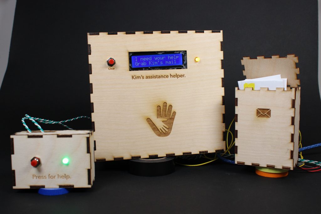
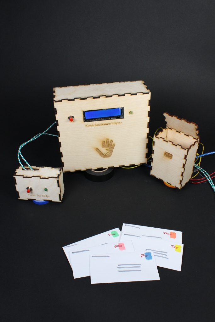
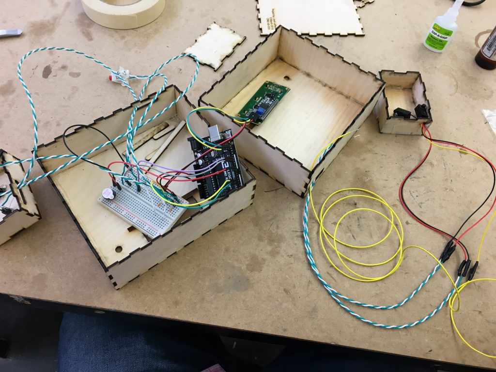
This is the full notification system. The press for help box would remain in the home of one in need, the mailbox is representative of the actual mailbox, and the central box acts as the sensor/reader with both visual and auditory output.
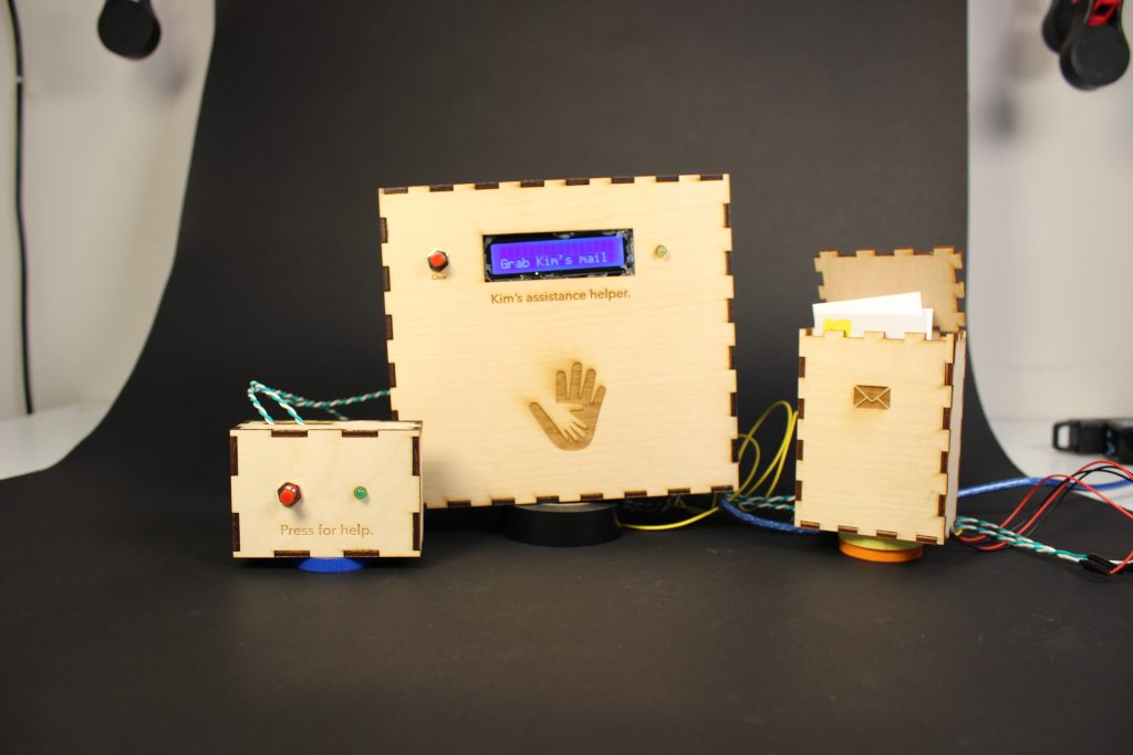
Mail sensor message
Process
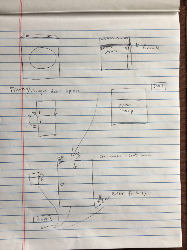
Some of my many initial sketch ideas
During this beginning of the project I had a hard time evaluating what a “good” project would be. I also wrestled with deciding on a device that I could be build that would be truly helpful and not just a novel collection of electronics.
This led me to explore ideas from adding a temperature thermostat to my oven, creating an RFID tag+music system at home and many other option.
As I pondered this question, I landed on the idea to combines several sensors and buttons to assist me in helping our landlord who often needs our help from us. The sensors would allow a more convent notification about what she needs and when she needs help.
During the process there were two key decision points that shaped the direction of the project.
- First, would I guilds product solely for my own benefit or something this was of a more community benefit. If I built for a community of people including me, I felt that the finished product should be prototyped at a higher resolution.
- Second, Once I had settled on a direction, I explored and researched common notification system patterns. From there I incorporated the principles to guid how to display the need request via light, buzzer, lcd text output.
Steps
- Initial sketches
- Connecting the LCD liquid crystal display
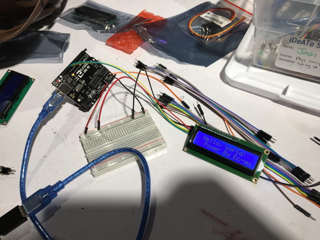
Connecting the LiquidCrtystal LCD display
- Adding notification buttons
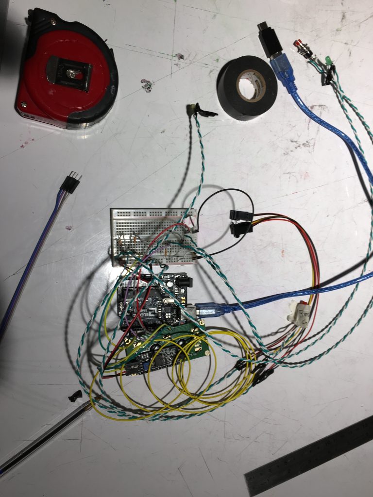
Notification and IR sensor testing
- Providing system feedback LED lights
- Adding IR sensors
- Integrating buzzer
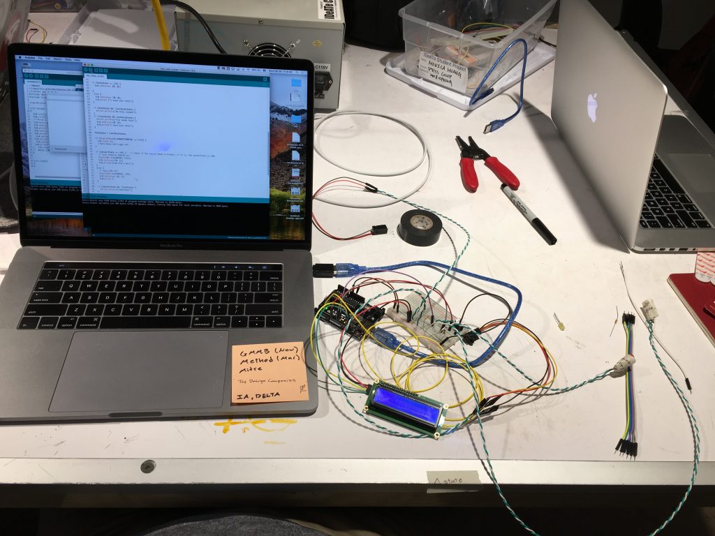
Full system test
- Creating Laser cutting plans
- Laser cutting
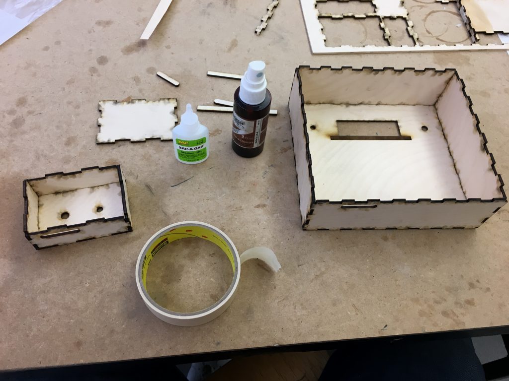
Assembling laser cut pieces
- Assembling prototype
Assembling prototype (box+ wires)
Discussion
- Self critique: I am happy with the result of this project. I feel like I made something meaningful and interesting. I feel that the project stretched me just enough by integrating new hardware, sensors, and coding logic. Being able to make something with a specific purpose made my design and build much easier. I think that by adding the extra watered logos, text and placing the end product into a clean container, that the critique was much lighter than I had expected.
- Surprises: I found that by giving the electronic form by placing them in the boxes or representative forms made the whole code seem more deliberate and purposeful. I was also surprised at how simple variables could allow me tackle a seemingly moderate level of code complexity. I am now excited to present this to our landlord and try some user testing. One major surprise for meeting is that some systems could use pull up code to act as ground instead of having specific resistors between the arduino’s 5V output and the loop back to the Arduino.
- What I learned: I learned that I am better at coding than I initially thought. Thought each individual piece was difficult, combining them felt natural and less complex. This project help solidify the use of mills and Boolean variables in my mind. Next time, I think that I’d create an outline or sketch of my intended purpose and interactions before jumping into the code. Being introduced to the LCD display opened the possibility of displaying specific news int he future.
- Next steps. I plan to show this to our landlord and get her feedback on whether she feels it would be more useful than knocking on her ceiling with a broom to ask for our help. then, I’d iterate on her feedback and instal the project t at home for 2 weeks to observe actual use cases. I’d be interested to see if she even likes and then if it increases here ask for help and whether it would get annoying for me.
Technical Stuff
Components
- Arduino, R3
- Small breadboard
- IR breakbeat sensor
- Buzzer, Piezo
- (2) momentary push buttons
- (2) LED lights
- LCD liquid crystal display
- Wires
- 1/8″ plywood
- Laser cutter
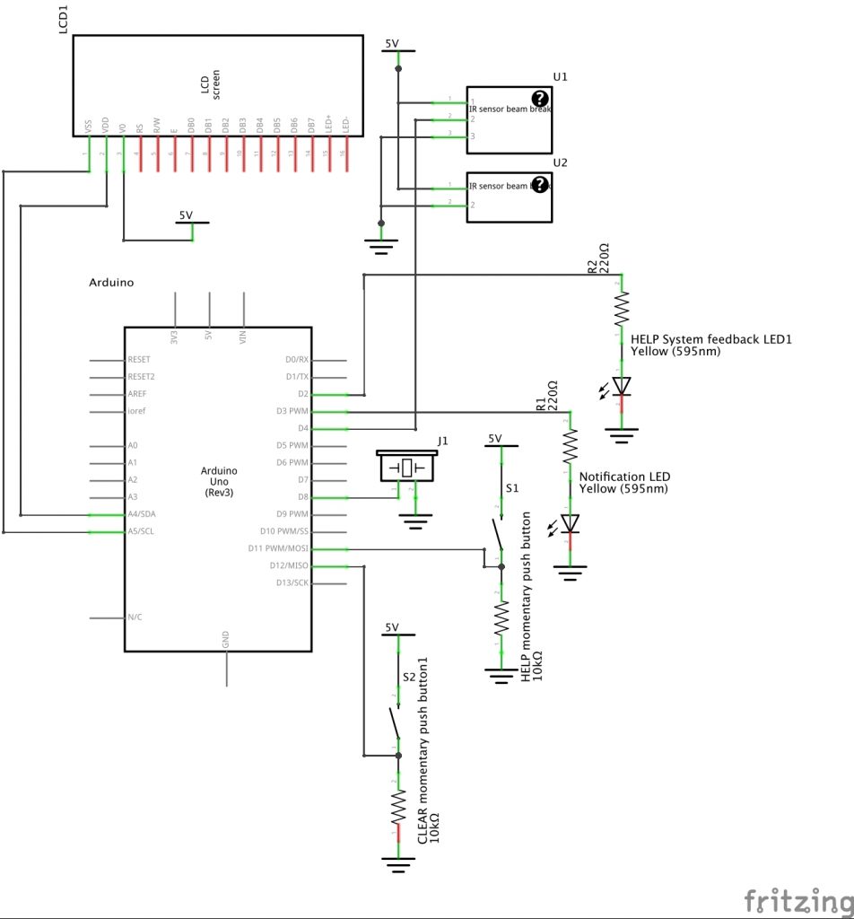
Schematic
Code
/*
* Turn a servo when a switch throws.
*
* The intended use was to pop a balloon when a door opened.
*
* Copyright 2018 Josh LeFevre.
*
* Permission is hereby granted, free of charge, to any person obtaining a
* copy of this software and associated documentation files (the “Software”),
* to deal in the Software without restriction, including without limitation
* the rights to use, copy, modify, merge, publish, distribute, sublicense,
* and/or sell copies of the Software, and to permit persons to whom the
* Software
* is furnished to do so, subject to the following conditions:
*
* The above copyright notice and this permission notice shall be included in
* all copies or substantial portions of the Software.
*
* THE SOFTWARE IS PROVIDED “AS IS”, WITHOUT WARRANTY OF ANY KIND, EXPRESS OR
* IMPLIED, INCLUDING BUT NOT LIMITED TO THE WARRANTIES OF MERCHANTABILITY,
* FITNESS FOR A PARTICULAR PURPOSE AND NONINFRINGEMENT. IN NO EVENT SHALL
* THE AUTHORS OR COPYRIGHT HOLDERS BE LIABLE FOR ANY CLAIM, DAMAGES OR OTHER
* LIABILITY, WHETHER IN AN ACTION OF CONTRACT, TORT OR OTHERWISE, ARISING FROM,
* OUT OF OR IN CONNECTION WITH THE SOFTWARE OR THE USE OR OTHER DEALINGS IN THE
* SOFTWARE.
*/
#define LEDPIN 13
#define MAILPIN 4
int sensorState = 0, lastState = 0; // variable for reading the pushbutton status
#include <Wire.h>
#include <LiquidCrystal_I2C.h>
LiquidCrystal_I2C lcd(0x3F, 16, 2); // set the LCD address to 0x3F for a 16 chars and 2 line display
const int CLEARBUTTONPIN = 11;
const int HELPBUTTONPIN = 12;
const int BUZZERPIN = 8;
int helpState = 0, lastHelpState = 0;
int clearState = 0, lastClearState = 0;
int helpLED = 2;
int notificationLED = 3;
bool firstHelpPress = true;
bool Cleared = false;
unsigned long helpTimer = 1000000000;
void setup() {
// initialize the LED pin as an output:
pinMode(LEDPIN, OUTPUT);
// initialize the sensor pin as an input:
pinMode(MAILPIN, INPUT);
digitalWrite(MAILPIN, HIGH); // turn on the pullup
pinMode(CLEARBUTTONPIN, INPUT);
pinMode(HELPBUTTONPIN, INPUT);
pinMode(BUZZERPIN, OUTPUT);
pinMode(notificationLED, OUTPUT);
pinMode(helpLED, OUTPUT);
lcd.init();
lcd.backlight();
digitalWrite(BUZZERPIN, LOW);
digitalWrite(notificationLED, LOW);
digitalWrite(helpLED, LOW);
Serial.begin(9600);
}
void loop() {
sensorState = digitalRead(MAILPIN); // read the state of the mail IR sensor value:
if (digitalRead(HELPBUTTONPIN) == HIGH && firstHelpPress) {
lcd.setCursor(0, 0);
lcd.print(“I need your help”);
Serial.println(“help”);
helpTimer = millis() + 5000;//use 180000 or 360000 for real timer
digitalWrite(notificationLED, HIGH);
digitalWrite(helpLED, HIGH);
firstHelpPress = false;
Serial.print(“help timer”);
Serial.print(helpTimer);
Serial.print(“millis”);
Serial.println(millis());
Cleared = false;
//turn on led light as Kim confirmation
}
if (helpTimer <= millis() && !Cleared) {
digitalWrite(BUZZERPIN, HIGH);
Serial.println(“Notification Buzzer”);
}
if (digitalRead(CLEARBUTTONPIN) == HIGH) {
lcd.clear ();
digitalWrite(BUZZERPIN, LOW);
digitalWrite(notificationLED, LOW);
digitalWrite(helpLED, LOW);
firstHelpPress = true;
Cleared = true;
Serial.println(“cleared”);
//turn Help LED light off
}
if (sensorState == LOW) { // check if the sensor beam is broken, if it is, the sensorState is LOW:
// turn Arduino PINLED on:
digitalWrite(LEDPIN, HIGH);
lcd.setCursor(0, 1);
lcd.print(“Grab Kim’s mail”);
}
else {
// turn LED off:
digitalWrite(LEDPIN, LOW);
lcd.setCursor (0, 1);
lcd.print (” “);
}
if (sensorState && !lastState) {
Serial.println(“Unbroken”);
Serial.println(“No Mail”);
}
if (!sensorState && lastState) {
Serial.println(“Broken”);
Serial.println(“Mail is here “);
lcd.setCursor(0, 1);
lcd.print(“Grab Kim’s mail”);
}
lastState = sensorState;
}
Schematic
Leave a Reply
You must be logged in to post a comment.