What is it?
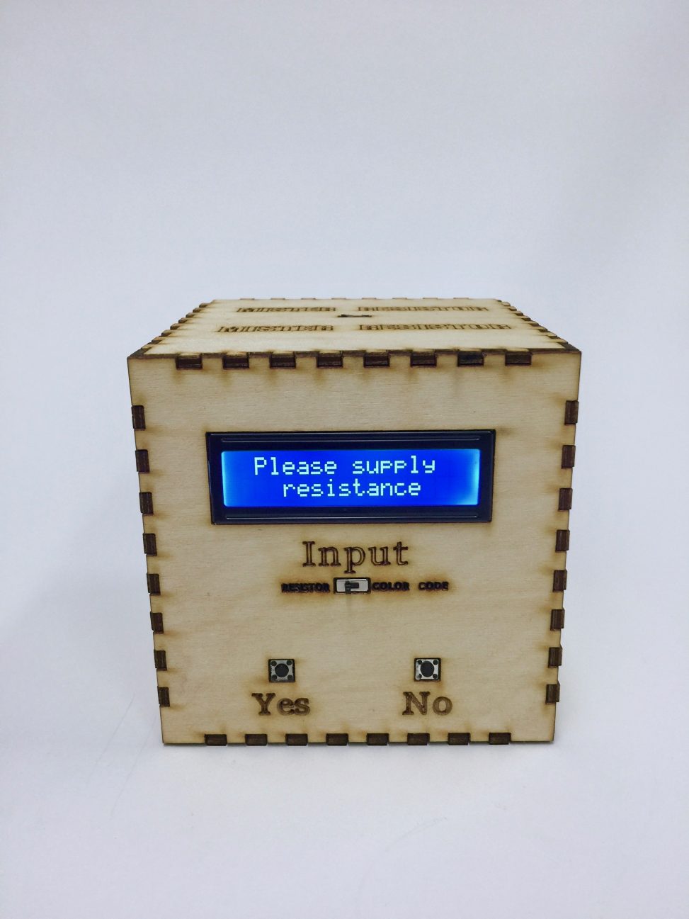
Mister Resistor is an assistive device that helps the user determine the value of a resistor, either by applying the actual resistor or by inputting the color code of the resistor.
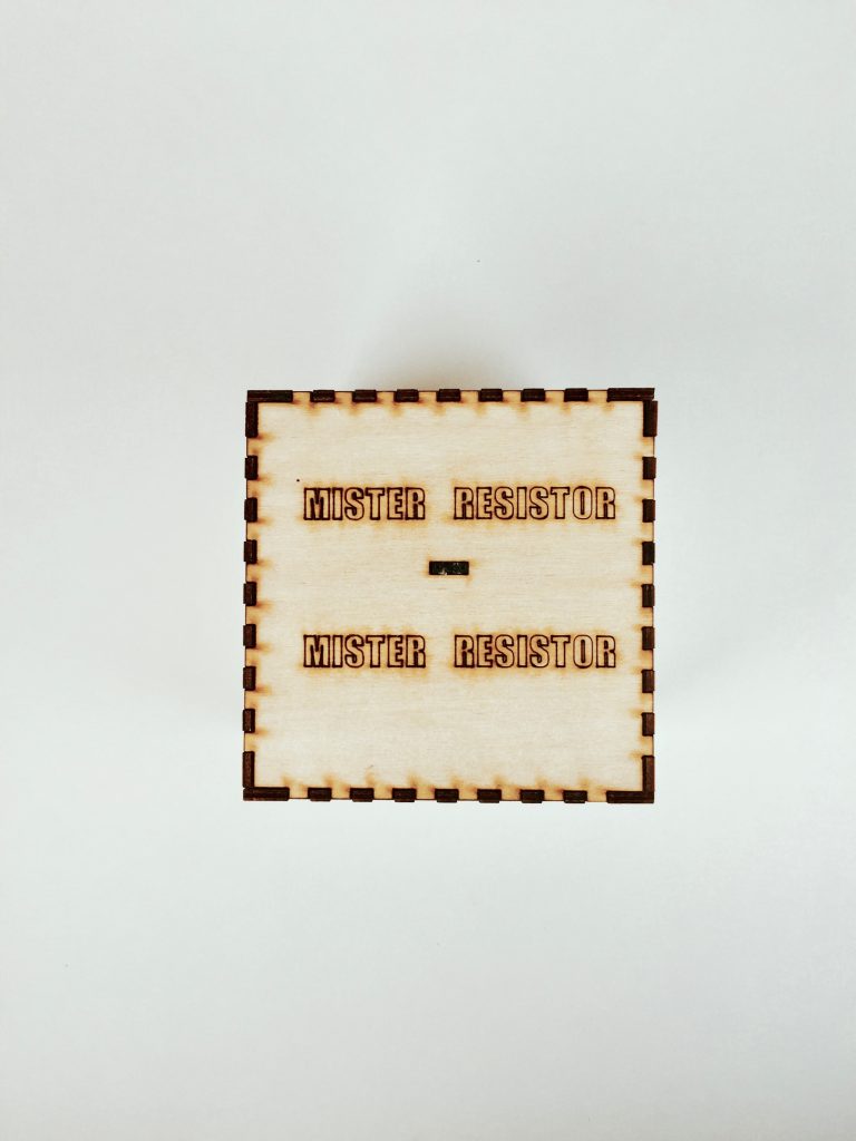
An aerial view of Mister Resistor
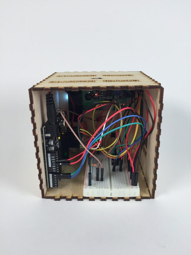
The internals
Did you run into any problems during the creation process?
Initially, I had the LCD display and the pushbuttons connected to the same 5V output coming from the Arduino. While testing my device, I realized that any time the pushbutton was pressed, it would affect the LCD display. The display would flash on and off, and sometimes even start displaying special characters that were out of my control. In search of a way to keep the user inputs and the display separate, I decided to tie the pushbuttons and the switch to the 3.3V output coming from the Arduino. This modification helped the display return predictable outputs, while still retaining the functionality of my device.
Another challenge I faced while creating this device was making it more elaborate. I felt that simply displaying a resistance value by applying a resistor was too simple of a project. One direction I tried to go in was to display the color code of the resistor onto 3 RGB LEDs, after determining the resistance. However, I decided not to pursue this idea because too many of the colors could not be displayed using such LEDs (eg. orange, black, brown). Instead, I decided to add the dual functionality of asking the user what the color code was, and returning the appropriate resistance value. In my opinion, this added feature made the device much more useful and interactive.
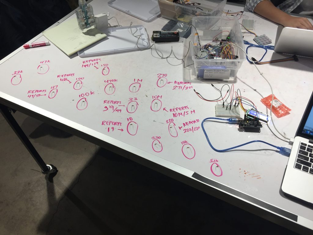
Testing the precision of the device using various resistors
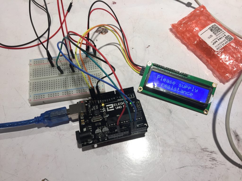
Early iteration of the project with no resistor applied
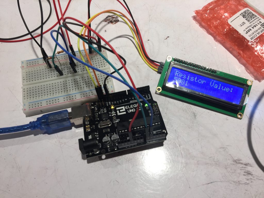
Early iteration of the project with a 5.1 kΩ resistor applied
Did anything surprise you throughout the creation process?
Actually, several minutes before the beginning of the crit, more testing helped me realize that the results I got from inputting an actual resistor did not match up with the results I got from inputting a color code. My first guess was that the hot glue I used added extraneous resistance to my circuit. I switched the wires that were attached to the input resistor and I still didn’t get the results I wanted. It was then that I realized the problem lied within the Color Code input mode. When I designed the logic for the Color Code input mode, I thought that the colors represented a number of the following form:
COLOR_1.COLOR_2 * 10^(COLOR_3),
but it actually represents this form:
((COLOR_1 * 10)+COLOR_2) * 10^(COLOR_3). So this decoding of colors came as a surprise to me, but by simply updating the software component of my device, I was able to achieve valid results and my device worked as intended.
Another surprise that came to me was that the input resistance ports were difficult for users to operate. Since I conceived the idea, the ports on top of the device made sense to me, but it ended up being slightly unclear to new users of the device.
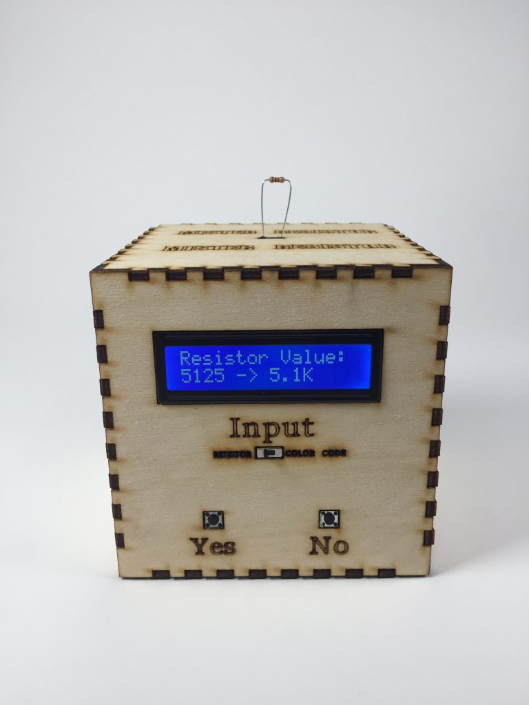
Final iteration of the project with a 5.1 kΩ resistor applied
What did you learn by doing this project?
Well, the first big takeaway I got from this project was how to properly read the color code of a resistor. I also learned that although RGB LEDs can display a variety of colors, it cannot display every color. I learned how to use an LCD display, which I plan to use for future projects because it allows me to easily provide users with text output. I also learned how to create those laser cut faces for the enclosure. I have been meaning to learn how to make them ever since I was inspired by other peoples’ Surprise! projects. Lastly, I learned that I need to exhaustively test my device before the crit, in order to prevent any similar functionality scares.
How would you do things differently in a future iteration of this project?
I still think it would be cool to have some LEDs display the color code of the input resistor. However, I’m not sure what LEDs I could use to display a wider variety of colors. I would also need more analog pins since I needed 3 to encode a single color value onto an RGB LED, and there are only 6 analog pins on an Arduino Uno. Additionally, in Resistor input mode, my project is designed specifically to match resistance values on the labelled bins in the IDeATe room. In a future iteration, I could try matching a broader range of resistance values. One last change I might make would be to simplify the way that users supply an input resistor. Having metal plates that the resistor legs could rest on might have provided this ease of use.
Are you satisfied with the way this project turned out?
I am extremely satisfied with how this project turned out. It’s definitely something I can see myself using often and even when I’m building new projects. I’m glad I was able to get my device to a fairly compact size, especially since compactness was not a main target point for my Surprise! project. Additionally, I’m glad that I was able to run my project using the battery, as opposed to using my laptop, which is how I powered my Surprise! project.
In the end, I’m always glad to see my ideas come to fruition. I’m excited to continue building awesome, yet useful things in the future.
Schematic:
![]()
Code Snippet:
String askColor ()
{
  while (digitalRead(noButton)) {
    if (digitalRead(switchPin)) {
      return "X";
    }
  }
  lcd.setCursor(0,1);
  lcd.print("BLACK?");
  // pause execution until either button is pressed
  while (buttonsOpen()) {
    if (digitalRead(switchPin)) {
      return "X";
    }
  }
  if (digitalRead(yesButton))
  {
    lcd.setCursor(0,1);
    lcd.print("BLACK!");
    delay(1000);
    // wait for button to be unpressed
    while (digitalRead(yesButton)) {
      if (digitalRead(switchPin)) {
        return "X";
      }
    }
    return "BLACK";
  }
  else if (digitalRead(noButton))
  {
    while (digitalRead(noButton)) {
      if (digitalRead(switchPin)) {
        return "X";
      }
    }
    lcd.setCursor(0,1);
    lcd.print("BROWN?");
This snippet exhibits gives a glimpse as to how I was able to pause execution until the user pressed a button, or switch between modes without getting stuck. I would remain in a while loop until either the Yes or No button were pressed, and only exit unless a button was pressed, or the switch was flipped. If a button were pressed, execution would be halted again until the user let go of the button. If the switch was flipped, the program would exit the helper function and continue to exit consecutive calls to the function until it returned to the beginning of the loop function, where it checked which mode the device was in. Some comments in the code provide clarification as to what the following statements are doing.
The actual code can be found here:
https://github.com/adrielmendoza/60223/tree/master/MisterResistor
Leave a Reply
You must be logged in to post a comment.