Overview
A device that displays current air quality and keeps track of the high and low points of air quality.
Gif of the LCD display showing the current air quality level and the LED light indicating that the air quality is good.
Detail Images:
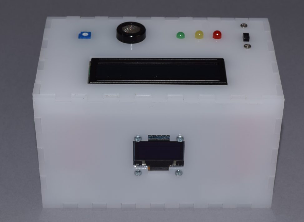
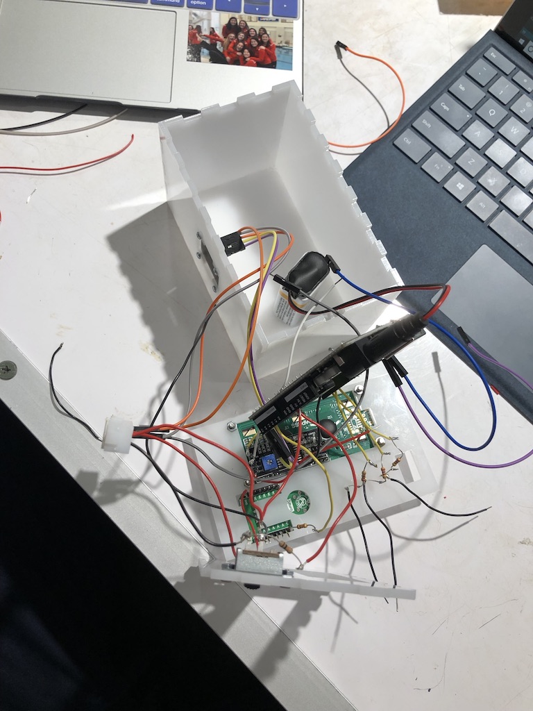
Close up of internal component of top of box. This photo highlights my attention to detail when fitting my model with the LEDs, LCD screen, air quality sensor, and switch.
The circular and rectangular cutouts in the top right corner of the above picture were not part of my original design, but I decided to incorporate them because the soldering on the gas sensor did not allow it to lie flat on the acrylic. These cutouts solved this problem.
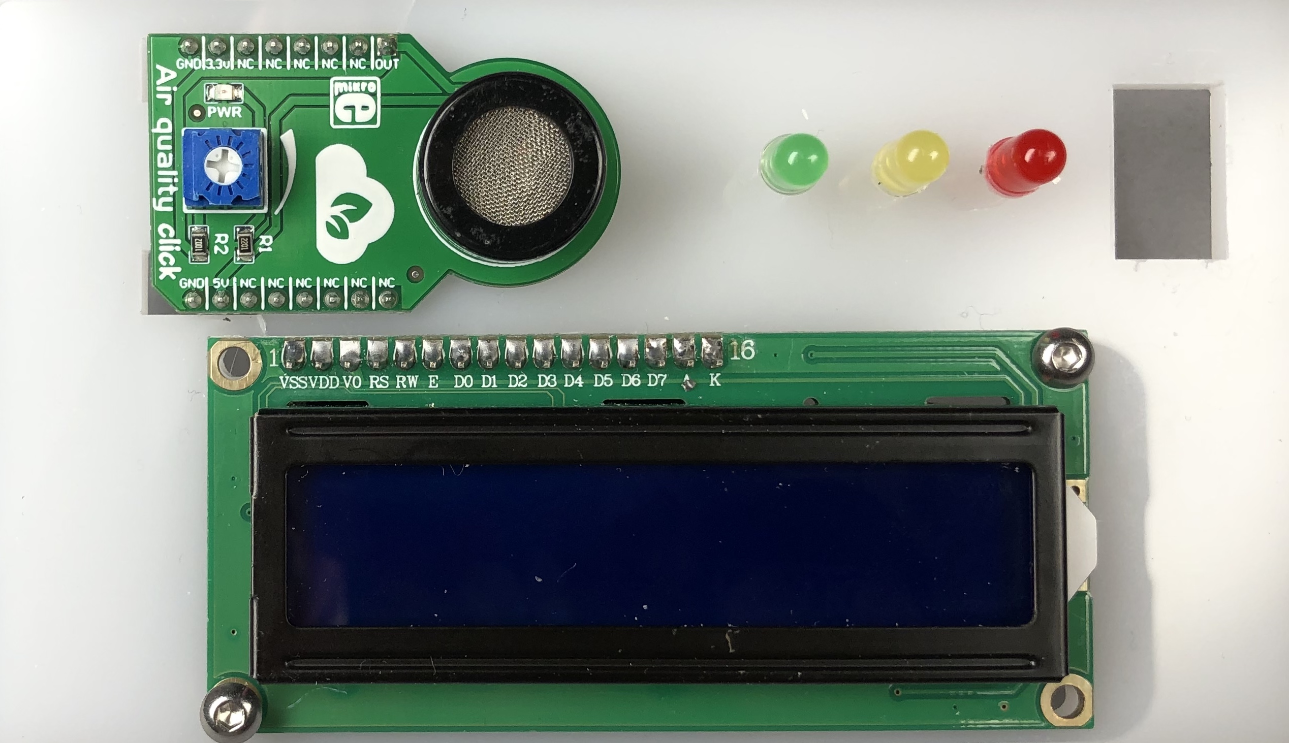
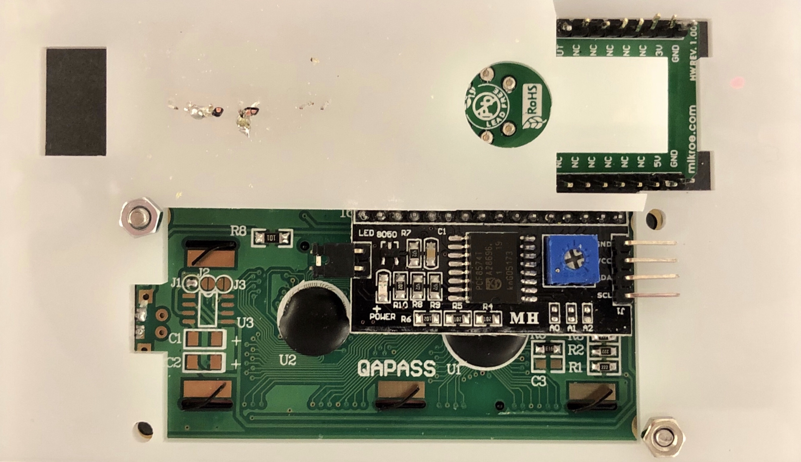
Close up of front side of internal component of box lid with all electrical components except for the switch fitted into it.
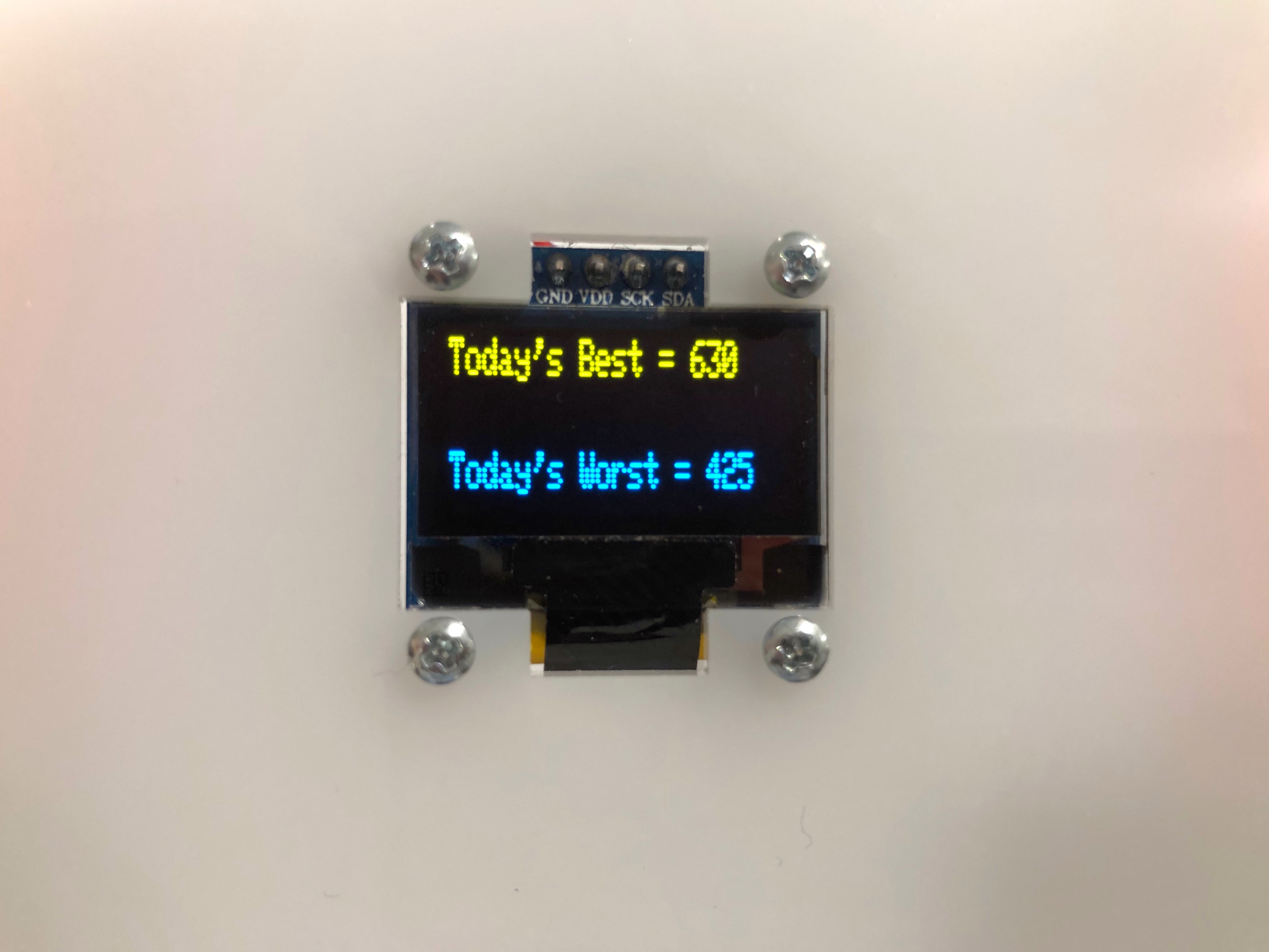
Photo that illustrates the day’s best and worst points of air quality being displayed on the OLED display.
Process:
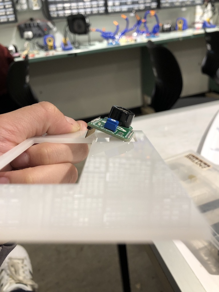
An early iteration of a part of the box that the new sensor did not fit into.
Final iteration of box before fitting all electrical components in it.
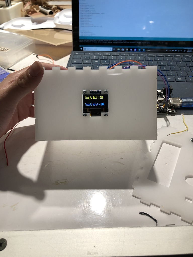
Fitting the OLED display into the box and outputting the high and low readings from the gas sensor.
Many of my process decisions were regarding the physical appearance of my project. For the most part, I knew how I wanted my device to function and which electronic components I wanted to use. The only significant change in terms of my electronic components that I made during the process was switching which gas sensory I would be using since the first one arrived damaged. The rest of my process decisions were regarding the device’s aesthetics. I chose the translucent white acrylic because I felt it gave the product a clean, fresh look and thought it would be interesting to vaguely see the electrical components inside the box. I chose to make my box extremely customized in the sense that every single cut out was perfectly measured for whatever hardware was going to be placed in it. I felt that this would make the device look more polished which seemed important because the purpose of this device is for it to be seen in order to gather what the general air quality of the room currently is or has been. It took me many iterations and hours in SolidWorks and the makerspace to get my box to turn out just right, but I am really happy with the way it turned out physically.
I was originally going to display a graph of the air quality over time on the OLED display but was ultimately unable to figure out how to do so given the time constraints. If I were to make another iteration of this device, I think I would try to play around with the OLED display and Arduino code to get a graph to display and update over time.
I also did not initially plan on using an OLED display in addition to the LCD display. However, after some discussion with Zach, I decided to incorporate the OLED display to add a bit more complexity to the project. Unfortunately, I wasn’t quite able to introduce the complexity of the graph described above.
Discussion:
This project was initially inspired by a teammate of mine who is allergic to chlorine and has asthma. As divers, we sometimes have to practice or compete in a pool where the air quality is bad, and this can negatively impact our performance. Thus, I decided to build an air quality monitor. Unfortunately, I was not particularly thrilled with the final outcome of my project. I worked really hard on the aesthetics of the project and the technical aspects; however, I focused on these things separately, thinking I would be able to easily combine them. I appreciated the comments I received during the critique in class. One person wrote “nicely put together project. Very interesting idea and approach. One aspect that may help with bulkiness without having to solder may be to cut the wires shorter. This way you can still use them as jumper wires and also potentially minimize the bulkiness.” I initially got all the electronic components wired together and working using jumper wires but then decided to solder the connections to make them more stable/permanent. The jumper wires were very prone to falling out of the breadboard/disconnecting from the sensor/displays I was using, especially when I was situating everything inside my box. To my dismay, after soldering all my connections, my electronic components did not function as they had with the jumper wires. If I were to make another iteration of this project, I think would try to use shorter wires to minimize bulkiness, and I would very carefully place the wires in the box to avoid wires from falling out. I also received a comment that said “really nice aesthetic to the project and very helpful since its intended for someone else as well. Cable management is key when putting something in a box, could tape them together.” I think the idea of taping the cables together is practical and something I might do if I were to make another iteration of this device.
Throughout the process of designing and building this device I realized that I really enjoy creating custom models in SolidWorks and laser cutting these designs. Unfortunately, I spent a bit too much time on the physical aspect of the project when I should have been equally distributing my time between the technical and physical components. Next time I will focus on getting all electrical components to function as intended before I prototype materials for the device itself. It was a bit difficult for me to do this for this particular project since the sensor I was going to use arrived damaged and I did not receive the replacement until the day before the final project was due. In hindsight, I probably should have changed my project to use components that are all readily available after the first sensor arrived damaged because then I would have had more time to work on the electrical components of my project.
I do not plan to create another iteration of this project, but if I were going to do so I would definitely make the box bigger so that all of the wires and electronics fit inside it comfortably. I would also make the LEDs more visible from further away so the user could quickly glance at the device from a distance and determine the room’s air quality level. I would do this by either using larger LEDs or making the LEDs stick out further from the surface of the box or both.
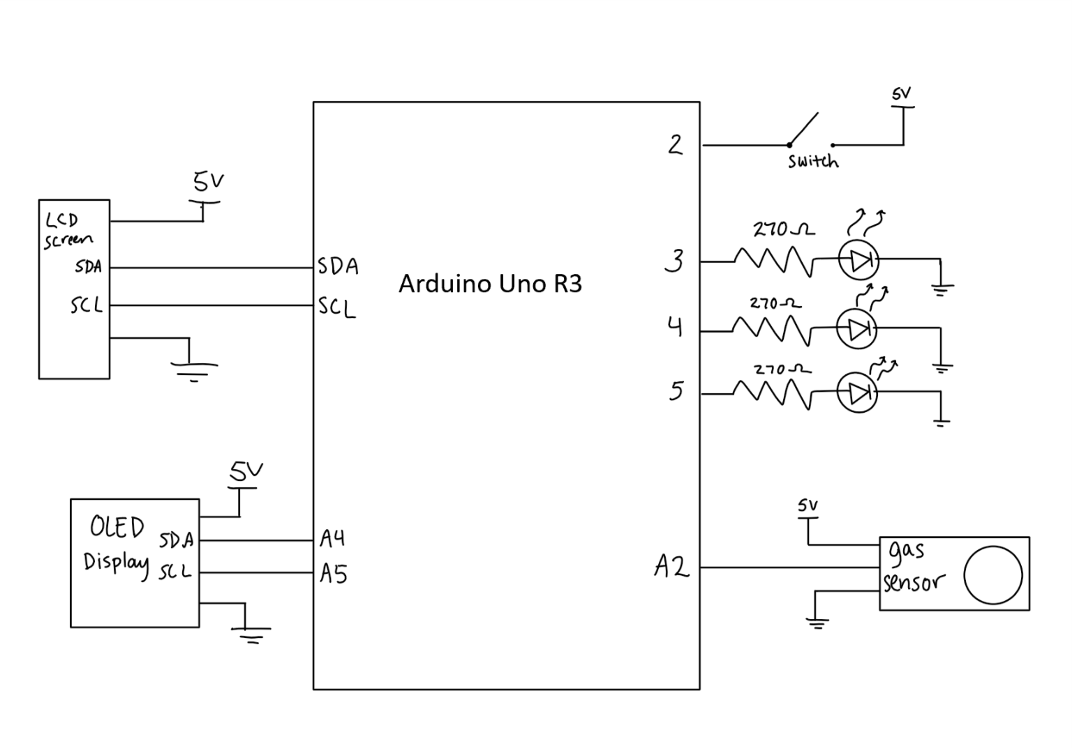
Schematic:
Code:
- <span class="com">/*Air Quality Sensor
- * This code reads data from a gas sensor to determine air quality.
- * The high and low of the collected data is recorded and these values
- * are printed to an OLED display and update as necessary. The live data
- * is printed to the LCD screen. This code also controls 3 LEDs of different
- * colors. One LED will be lit at a time depending on the current air quality
- * read by the sensor. The device is only active when the switch is ON.
- *
- * The gas sensor must be connected to an analog pin; I chose A2.
- * Both the LCD and OLED display must have a specified address to allow data
- * to be printed to them. Generally, 0x27 and 0x3C are used for this. I chose
- * 0x27 for the LCD screen and 0x3C for the OLED display.
- */</span><span class="pln">
- </span><span class="com">#include</span><span class="pln"> </span><span class="str"><Adafruit_GFX.h></span><span class="pln">
- </span><span class="com">#include</span><span class="pln"> </span><span class="str"><Adafruit_SSD1306.h></span><span class="pln">
- </span><span class="com">#include</span><span class="pln"> </span><span class="str"><Wire.h></span><span class="pln">
- </span><span class="com">#include</span><span class="pln"> </span><span class="str"><LiquidCrystal_I2C.h></span><span class="pln">
- </span><span class="typ">LiquidCrystal_I2C</span><span class="pln"> screen</span><span class="pun">(</span><span class="lit">0x27</span><span class="pun">,</span><span class="pln"> </span><span class="lit">16</span><span class="pun">,</span><span class="pln"> </span><span class="lit">2</span><span class="pun">);</span><span class="pln">
- </span><span class="com">#define</span><span class="pln"> OLED </span><span class="lit">0x3C</span><span class="pln">
- </span><span class="typ">Adafruit_SSD1306</span><span class="pln"> display</span><span class="pun">;</span><span class="pln">
- </span><span class="kwd">const</span><span class="pln"> </span><span class="kwd">int</span><span class="pln"> GASPIN </span><span class="pun">=</span><span class="pln"> A2</span><span class="pun">;</span><span class="pln">
- </span><span class="kwd">const</span><span class="pln"> </span><span class="kwd">int</span><span class="pln"> RED </span><span class="pun">=</span><span class="pln"> </span><span class="lit">4</span><span class="pun">;</span><span class="pln">
- </span><span class="kwd">const</span><span class="pln"> </span><span class="kwd">int</span><span class="pln"> YELLOW </span><span class="pun">=</span><span class="pln"> </span><span class="lit">5</span><span class="pun">;</span><span class="pln">
- </span><span class="kwd">const</span><span class="pln"> </span><span class="kwd">int</span><span class="pln"> GREEN </span><span class="pun">=</span><span class="pln"> </span><span class="lit">3</span><span class="pun">;</span><span class="pln">
- </span><span class="kwd">const</span><span class="pln"> </span><span class="kwd">int</span><span class="pln"> SWITCHPIN </span><span class="pun">=</span><span class="pln"> </span><span class="lit">2</span><span class="pun">;</span><span class="pln">
- </span><span class="kwd">int</span><span class="pln"> high </span><span class="pun">=</span><span class="pln"> </span><span class="lit">0</span><span class="pun">;</span><span class="pln"> </span><span class="com">//initialize high as 0 so it will be set to the first reading from the sensor </span><span class="pln">
- </span><span class="kwd">int</span><span class="pln"> low </span><span class="pun">=</span><span class="pln"> </span><span class="lit">1023</span><span class="pun">;</span><span class="pln"> </span><span class="com">/*initialize low as 1023 (the max value of the sensor) so it will be set to
- the first reading from the sensor. After the first piece of data is read, the high and low
- variables will update properly.*/</span><span class="pln">
- </span><span class="kwd">int</span><span class="pln"> check</span><span class="pun">;</span><span class="pln">
- </span><span class="kwd">int</span><span class="pln"> gas</span><span class="pun">;</span><span class="pln">
- </span><span class="kwd">void</span><span class="pln"> setup</span><span class="pun">()</span><span class="pln"> </span><span class="pun">{</span><span class="pln"> </span><span class="com">//initialize LCD and OLED screens and setup pinModes</span><span class="pln">
- pinMode</span><span class="pun">(</span><span class="pln">GASPIN</span><span class="pun">,</span><span class="pln"> INPUT</span><span class="pun">);</span><span class="pln">
- pinMode</span><span class="pun">(</span><span class="pln">RED</span><span class="pun">,</span><span class="pln"> OUTPUT</span><span class="pun">);</span><span class="pln">
- pinMode</span><span class="pun">(</span><span class="pln">YELLOW</span><span class="pun">,</span><span class="pln"> OUTPUT</span><span class="pun">);</span><span class="pln">
- pinMode</span><span class="pun">(</span><span class="pln">GREEN</span><span class="pun">,</span><span class="pln"> OUTPUT</span><span class="pun">);</span><span class="pln">
- pinMode</span><span class="pun">(</span><span class="pln">SWITCHPIN</span><span class="pun">,</span><span class="pln"> INPUT_PULLUP</span><span class="pun">);</span><span class="pln">
- display</span><span class="pun">.</span><span class="kwd">begin</span><span class="pun">(</span><span class="pln">SSD1306_SWITCHCAPVCC</span><span class="pun">,</span><span class="pln"> OLED</span><span class="pun">);</span><span class="pln">
- display</span><span class="pun">.</span><span class="pln">clearDisplay</span><span class="pun">();</span><span class="pln">
- display</span><span class="pun">.</span><span class="pln">setCursor</span><span class="pun">(</span><span class="lit">0</span><span class="pun">,</span><span class="pln"> </span><span class="lit">0</span><span class="pun">);</span><span class="pln">
- display</span><span class="pun">.</span><span class="pln">display</span><span class="pun">();</span><span class="pln">
- screen</span><span class="pun">.</span><span class="pln">init</span><span class="pun">();</span><span class="pln">
- screen</span><span class="pun">.</span><span class="kwd">begin</span><span class="pun">(</span><span class="lit">16</span><span class="pun">,</span><span class="pln"> </span><span class="lit">2</span><span class="pun">);</span><span class="pln">
- screen</span><span class="pun">.</span><span class="pln">clear</span><span class="pun">();</span><span class="pln">
- screen</span><span class="pun">.</span><span class="pln">setCursor</span><span class="pun">(</span><span class="lit">0</span><span class="pun">,</span><span class="pln"> </span><span class="lit">0</span><span class="pun">);</span><span class="pln">
- screen</span><span class="pun">.</span><span class="kwd">print</span><span class="pun">(</span><span class="str">"Current Quality: "</span><span class="pun">);</span><span class="pln"> </span><span class="com">//display this at 1st row of LCD display</span><span class="pln">
- screen</span><span class="pun">.</span><span class="pln">setCursor</span><span class="pun">(</span><span class="lit">0</span><span class="pun">,</span><span class="pln"> </span><span class="lit">1</span><span class="pun">);</span><span class="pln"> </span><span class="com">//move cursor to 2nd row to display sensor data</span><span class="pln">
- screen</span><span class="pun">.</span><span class="kwd">print</span><span class="pun">(</span><span class="str">"532"</span><span class="pun">);</span><span class="pln">
- screen</span><span class="pun">.</span><span class="pln">backlight</span><span class="pun">();</span><span class="pln">
- screen</span><span class="pun">.</span><span class="pln">home</span><span class="pun">();</span><span class="pln">
- screen</span><span class="pun">.</span><span class="pln">noAutoscroll</span><span class="pun">();</span><span class="pln">
- screen</span><span class="pun">.</span><span class="pln">display</span><span class="pun">();</span><span class="pln">
- </span><span class="typ">Serial</span><span class="pun">.</span><span class="kwd">begin</span><span class="pun">(</span><span class="lit">9600</span><span class="pun">);</span><span class="pln">
- </span><span class="pun">}</span><span class="pln">
- </span><span class="kwd">void</span><span class="pln"> </span><span class="typ">OLEDWrite</span><span class="pun">()</span><span class="pln"> </span><span class="pun">{</span><span class="pln">
- </span><span class="com">//print to the OLED display the day's high/low points</span><span class="pln">
- display</span><span class="pun">.</span><span class="pln">setTextSize</span><span class="pun">(</span><span class="lit">1</span><span class="pun">);</span><span class="pln">
- display</span><span class="pun">.</span><span class="pln">setTextColor</span><span class="pun">(</span><span class="pln">WHITE</span><span class="pun">);</span><span class="pln">
- display</span><span class="pun">.</span><span class="pln">setCursor</span><span class="pun">(</span><span class="lit">0</span><span class="pun">,</span><span class="pln"> </span><span class="lit">0</span><span class="pun">);</span><span class="pln">
- display</span><span class="pun">.</span><span class="kwd">print</span><span class="pun">(</span><span class="str">"Today's Best = "</span><span class="pun">);</span><span class="pln">
- display</span><span class="pun">.</span><span class="kwd">print</span><span class="pun">(</span><span class="pln">gas</span><span class="pun">);</span><span class="pln">
- display</span><span class="pun">.</span><span class="kwd">print</span><span class="pun">(</span><span class="str">"Today's Worst = "</span><span class="pun">);</span><span class="pln">
- display</span><span class="pun">.</span><span class="kwd">print</span><span class="pun">(</span><span class="pln">gas</span><span class="pun">);</span><span class="pln">
- display</span><span class="pun">.</span><span class="pln">display</span><span class="pun">();</span><span class="pln">
- </span><span class="pun">}</span><span class="pln">
- </span><span class="com">//determine if the current air quality is > high </span><span class="pln">
- </span><span class="com">//or < low and change these values accordingly.</span><span class="pln">
- </span><span class="kwd">void</span><span class="pln"> highLow</span><span class="pun">(</span><span class="kwd">int</span><span class="pln"> curr</span><span class="pun">)</span><span class="pln"> </span><span class="pun">{</span><span class="pln">
- </span><span class="kwd">if</span><span class="pln"> </span><span class="pun">(</span><span class="pln">curr </span><span class="pun">></span><span class="pln"> high</span><span class="pun">)</span><span class="pln"> high </span><span class="pun">=</span><span class="pln"> curr</span><span class="pun">;</span><span class="pln">
- </span><span class="kwd">if</span><span class="pln"> </span><span class="pun">(</span><span class="pln">curr </span><span class="pun"><</span><span class="pln"> low</span><span class="pun">)</span><span class="pln"> low </span><span class="pun">=</span><span class="pln"> curr</span><span class="pun">;</span><span class="pln">
- </span><span class="pun">}</span><span class="pln">
- </span><span class="kwd">void</span><span class="pln"> loop</span><span class="pun">()</span><span class="pln"> </span><span class="pun">{</span><span class="pln">
- check </span><span class="pun">=</span><span class="pln"> digitalRead</span><span class="pun">(</span><span class="pln">SWITCHPIN</span><span class="pun">);</span><span class="pln">
- </span><span class="kwd">if</span><span class="pun">(!</span><span class="pln">check</span><span class="pun">){</span><span class="pln"> </span><span class="com">//only turn on device when switch is on</span><span class="pln">
- display</span><span class="pun">.</span><span class="pln">clearDisplay</span><span class="pun">();</span><span class="pln">
- display</span><span class="pun">.</span><span class="pln">display</span><span class="pun">();</span><span class="pln">
- screen</span><span class="pun">.</span><span class="pln">noBacklight</span><span class="pun">();</span><span class="pln">
- </span><span class="pun">}</span><span class="pln">
- </span><span class="kwd">else</span><span class="pun">{</span><span class="pln">
- display</span><span class="pun">.</span><span class="pln">display</span><span class="pun">();</span><span class="pln">
- screen</span><span class="pun">.</span><span class="pln">backlight</span><span class="pun">();</span><span class="pln">
- gas </span><span class="pun">=</span><span class="pln"> analogRead</span><span class="pun">(</span><span class="pln">GASPIN</span><span class="pun">);</span><span class="pln">
- screen</span><span class="pun">.</span><span class="pln">noAutoscroll</span><span class="pun">();</span><span class="pln">
- highLow</span><span class="pun">(</span><span class="pln">gas</span><span class="pun">);</span><span class="pln">
- </span><span class="com">//the following if/else statements turn on either the red, green,</span><span class="pln">
- </span><span class="com">//or yellow LED based on the data read from the sensor</span><span class="pln">
- </span><span class="kwd">if</span><span class="pun">(</span><span class="pln">gas </span><span class="pun"><</span><span class="pln"> </span><span class="lit">550</span><span class="pun">){</span><span class="pln">
- digitalWrite</span><span class="pun">(</span><span class="pln">RED</span><span class="pun">,</span><span class="pln"> HIGH</span><span class="pun">);</span><span class="pln">
- digitalWrite</span><span class="pun">(</span><span class="pln">YELLOW</span><span class="pun">,</span><span class="pln"> LOW</span><span class="pun">);</span><span class="pln">
- digitalWrite</span><span class="pun">(</span><span class="pln">GREEN</span><span class="pun">,</span><span class="pln"> LOW</span><span class="pun">);</span><span class="pln">
- </span><span class="pun">}</span><span class="pln">
- </span><span class="kwd">else</span><span class="pln"> </span><span class="kwd">if</span><span class="pun">(</span><span class="pln">gas </span><span class="pun"><</span><span class="pln"> </span><span class="lit">800</span><span class="pun">){</span><span class="pln">
- digitalWrite</span><span class="pun">(</span><span class="pln">YELLOW</span><span class="pun">,</span><span class="pln"> HIGH</span><span class="pun">);</span><span class="pln">
- digitalWrite</span><span class="pun">(</span><span class="pln">RED</span><span class="pun">,</span><span class="pln"> LOW</span><span class="pun">);</span><span class="pln">
- digitalWrite</span><span class="pun">(</span><span class="pln">GREEN</span><span class="pun">,</span><span class="pln"> LOW</span><span class="pun">);</span><span class="pln">
- </span><span class="pun">}</span><span class="pln">
- </span><span class="kwd">else</span><span class="pun">{</span><span class="pln">
- digitalWrite</span><span class="pun">(</span><span class="pln">GREEN</span><span class="pun">,</span><span class="pln"> HIGH</span><span class="pun">);</span><span class="pln">
- digitalWrite</span><span class="pun">(</span><span class="pln">YELLOW</span><span class="pun">,</span><span class="pln"> LOW</span><span class="pun">);</span><span class="pln">
- digitalWrite</span><span class="pun">(</span><span class="pln">RED</span><span class="pun">,</span><span class="pln"> LOW</span><span class="pun">);</span><span class="pln">
- </span><span class="pun">}</span><span class="pln">
- </span><span class="typ">Serial</span><span class="pun">.</span><span class="kwd">print</span><span class="pun">(</span><span class="str">"current sensor reading: "</span><span class="pun">);</span><span class="pln">
- </span><span class="typ">Serial</span><span class="pun">.</span><span class="pln">println</span><span class="pun">(</span><span class="pln">gas</span><span class="pun">);</span><span class="pln"> </span><span class="com">//print statement for debugging</span><span class="pln">
- </span><span class="typ">OLEDWrite</span><span class="pun">();</span><span class="pln">
- display</span><span class="pun">.</span><span class="pln">display</span><span class="pun">();</span><span class="pln">
- screen</span><span class="pun">.</span><span class="kwd">print</span><span class="pun">(</span><span class="pln">gas</span><span class="pun">);</span><span class="pln">
- screen</span><span class="pun">.</span><span class="pln">display</span><span class="pun">();</span><span class="pln">
- </span><span class="pun">}</span><span class="pln">
- delay</span><span class="pun">(</span><span class="lit">100</span><span class="pun">);</span><span class="pln">
- </span><span class="pun">}</span>
Comments are closed.