
by Connor Maggio and Nina Yoo
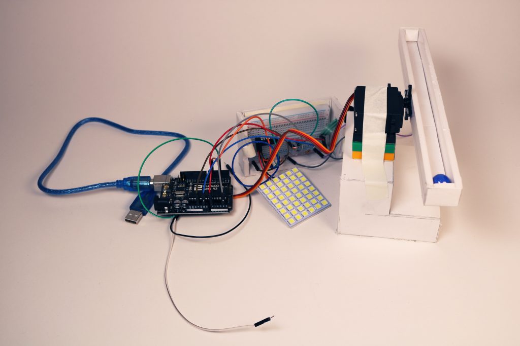
Description: Bright Balance is like a game where you change the brightness through a pressure sensor and see the motor change the angle of the ramp according to the brightness level.
Images:
-

Pressure-> Photosensor-> Motor -
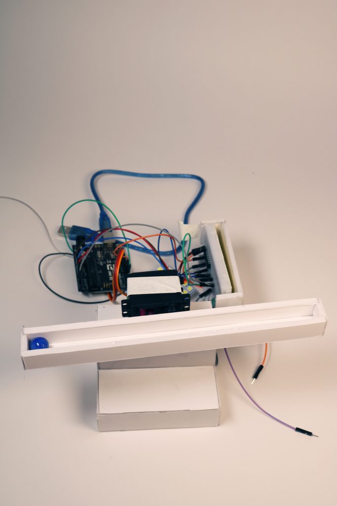
Showing how the mechanism looks when taken apart -
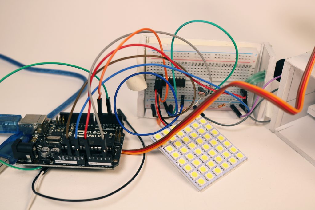
Wiring display -
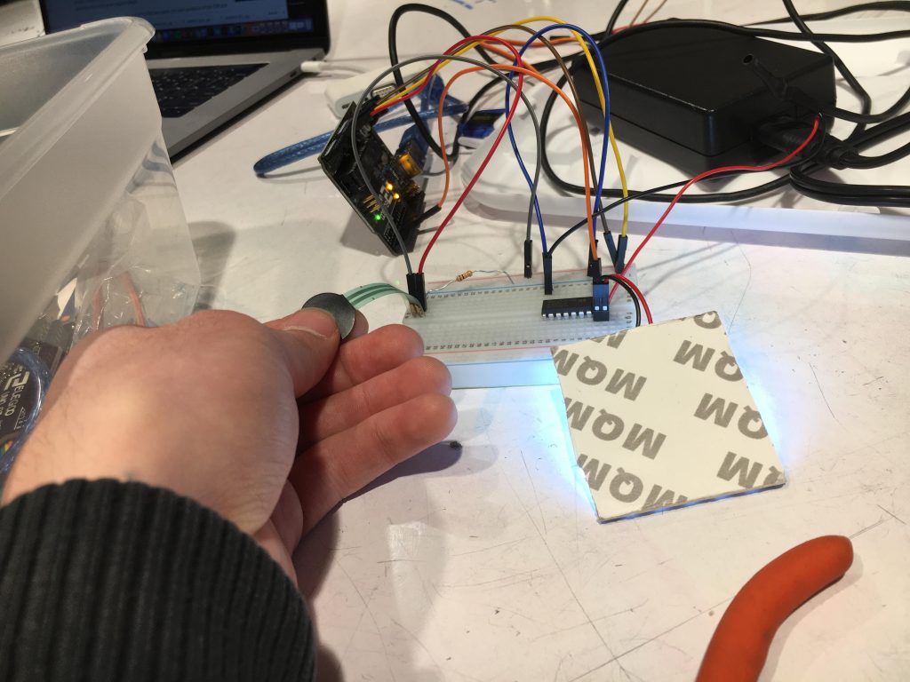
Front view of the mechanism. When pressure is applied to the sensor, light is emitted to the LED panel, then the photosensor reads the brightness and moves the motor according to the level of brightness.
Process Images:
-
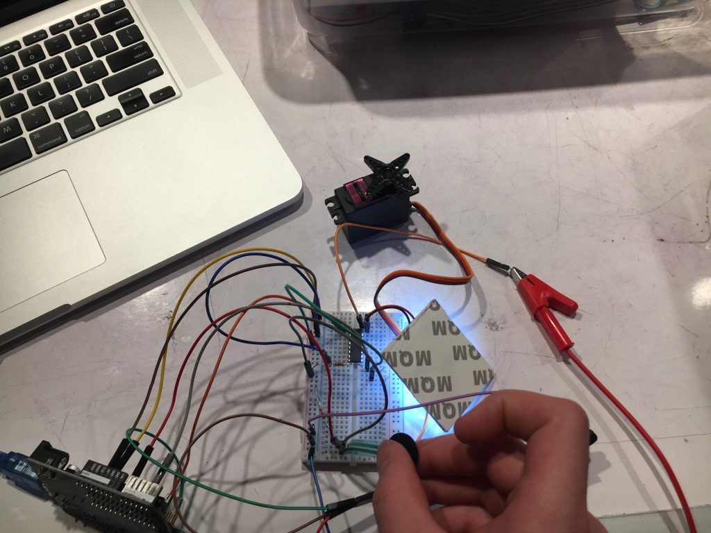
Implementing the motor(one that is stronger than the one that was provided before) seeing if the light and the motor worked together. Problems with this mechanism involved having it wired wrong so our first motor broke and then it jittering a lot due to the data being noisy. -
testing the pressure sensor with the light and playing with how sensitive it was. Problems occurred when the light was changing too rapidly or not at all -
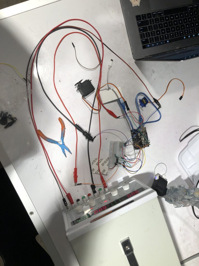
plugging into a bigger power source due to the motor requiring 5 volts and the light requiring 12 volts. Asked the professor to oversee the wiring so no problems occurred.
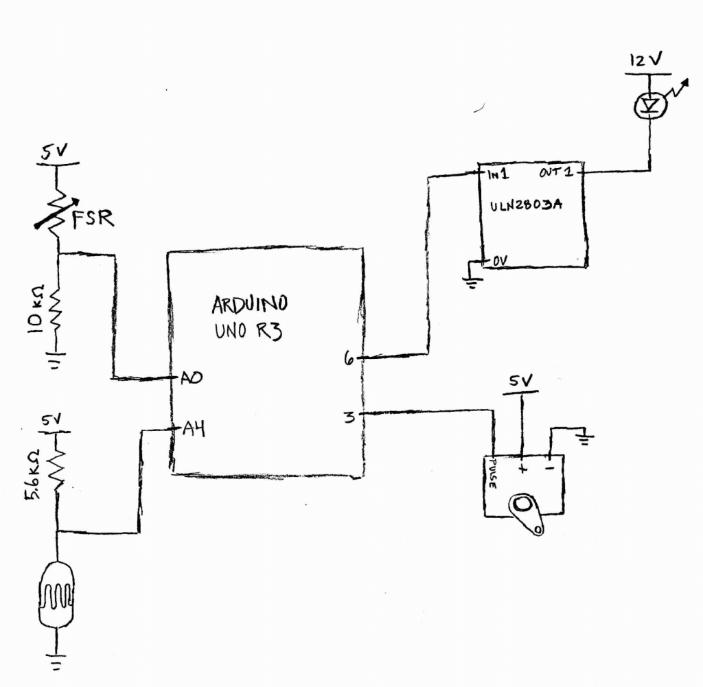
Schematic:
Code:

Bright Balance
Nina Yoo and Connor Maggio

Summary: The code below implements an FSR that maps brightness to an LED, which is sensed by a photoresistor that maps angle to a servo motor. There is also an exponential filter on the photoresistor values so the servo motor is normalized.

Inputs: 1 FSR, 1 photoresistor Outputs: 1 LED, 1 Servo


Collaboration: Robert Zacharias helped us with

using a power source for a few elements in our project.

He also helped us implement a transistor in order to

create a 12V switch.

Challenge: This project had more elements than any

previous project. Thus, there were a lot of wires to keep

track of and it was a challenge making sure everything

was in tact. For instance, at some point our servo was not

grounded correctly and it would not move.

Next time: It would be beneficial to use a smaller arduino

that we could fully house the project. In addition, I will

check the entire wiring of my projects before linking the

power to prevent burning out elements.


*/

#include<Servo.h>

int fsrAnalogPin = 0; // FSR is connected to analog 0
int LEDpin = 6; // connect LED to pin 6 (PWM pin)
int fsrReading; // the analog reading from the FSR resistor divider
int LEDbrightness;
int motorAngle;
int servoPin = 3; // pin the servo data line is plugged into
int photocell = A4;

float cur_reading;
float filtered_val = 0; // this variable, of type float (decimal), holds the filtered sensor value
const float PREV_WEIGHT = 0.85; // this variable, of type float (decimal), determines the previously filtered value's weight.
const float CUR_WEIGHT = 1 - PREV_WEIGHT;

Servo myLittleMotor;

void setup(void) {
Serial.begin(9600);
pinMode(fsrAnalogPin, INPUT);
pinMode(LEDpin, OUTPUT);
myLittleMotor.attach(servoPin); // set up the servo on that data pin
pinMode(photocell, INPUT);
filtered_val = analogRead(photocell);

// Print the intial value so we can see it
Serial.print("initial filtered value: ");
Serial.println(filtered_val);
}

void loop(void) {
fsrReading = analogRead(fsrAnalogPin);

// convert the integer value returned by analogRead
// to a float by casting it
cur_reading = (float)analogRead(photocell);

// Calculate the next filtered value
filtered_val = filtered_val * PREV_WEIGHT + cur_reading * CUR_WEIGHT;

// Print the filtered value so we can see it
Serial.print("filtered value: ");
Serial.println(filtered_val);

// change the range from the analog reading (0-1023)
// down to the range used by analogWrite (0-255)
LEDbrightness = map(fsrReading, 0, 1023, 0, 255);

// LED gets brighter the harder you press
analogWrite(LEDpin, LEDbrightness);

motorAngle = map(filtered_val, 50, 1000, 35, 120);
myLittleMotor.write(motorAngle);
}
Discussion: From the start we just started to brainstorm ideas that were interesting. We settled on Bright Balance and when we first began we started with a schematic giving the overall view of how it would work and what components it would require. However, though this step did help us begin the project, we did not really follow it as much when proceeding with our project. We turned to website tutorials to help us with our code as well as the wiring. It would have been easier for us if we had mapped or continuously updated our schematic as we went through the process.
The first component that we set up were the lights. At first, we had used the simple LED lights that were provided from earlier projects, but we needed something stronger. We then proceeded to go to a stronger LED, but that was also too weak. The professor then introduced us to an LED panel that had more than enough light, but required a 12 volt battery. We then proceeded to learn how to use bigger batteries and how we can connect it to the light source as well as the Arduino. It was helpful that the professor was with us during the wiring of the 12 volt battery to make sure everything went smoothly.
The next components we tackled was the pressure sensor and the photocell. It was easy to wire and code, but the data was noisy so we implemented “float” in order to filter out the data. This allowed for a much smoother response when printing the numbers/ looking at the graph.
After implementing the FSR and photocell, we converted that data into the motor. We used the filtered value that the photocell got from the light, which was read from the FSR, to then move the motor at different angles. We played with values of the motor to see how much angle it needed to move the marble around as well as keeping in mind the space around it. In the beginning, we had a small servomotor that was given to us in class, but then was introduced to a larger servomotor which required 5 volts. We broke the first motor, and after trying to rewire and code for a while, we realized we just needed another one.
Comments are closed.