by Erin Ryan and Helen Yu
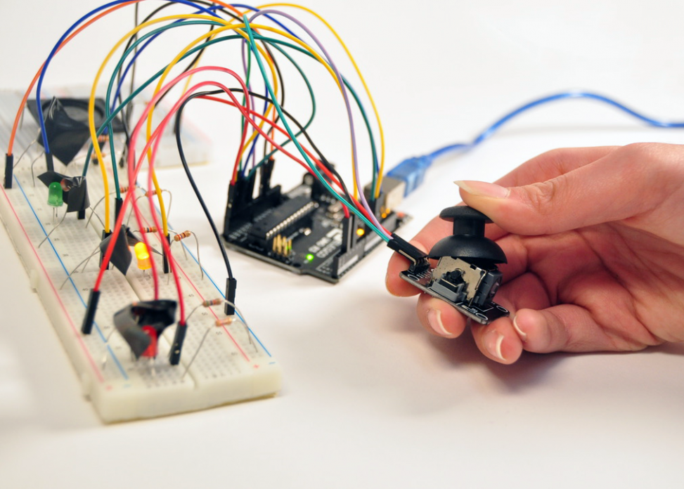
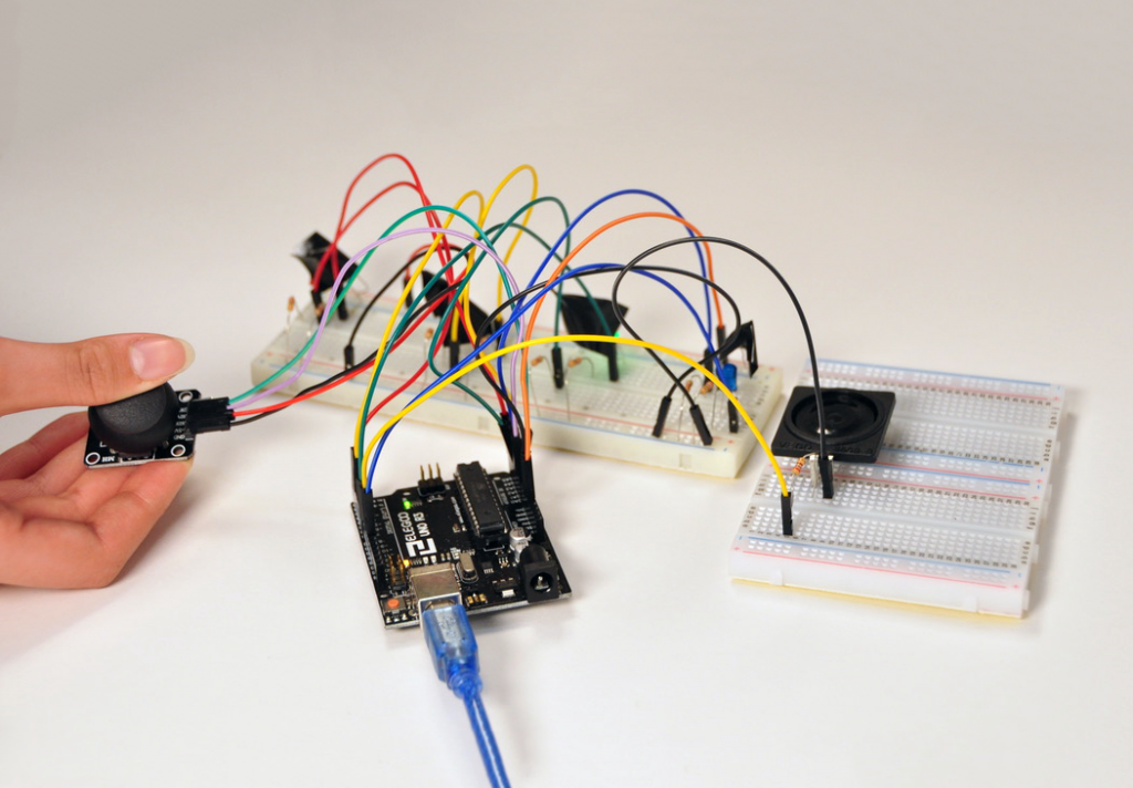
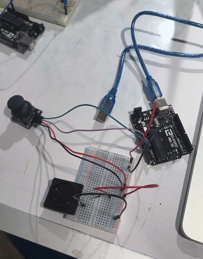
Fidget transforms the user’s movement of a joystick into a colored light, which in turn plays a note through a speaker.
Images:
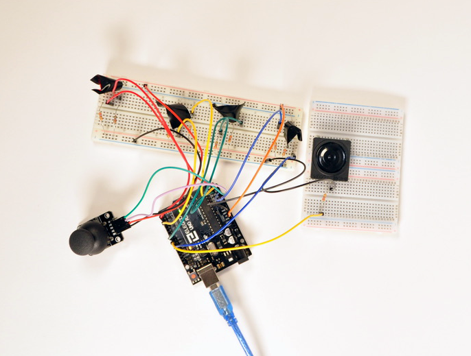
Overview shot of Fidget while the joystick is being used. You can also see that the green LED is lighting up. Bird’s eye view of fidget without anyone interacting with it. Detail shot of joystick being used while the yellow LED lights up.
https://vimeo.com/317862064
Fidget in action
Process Photos:
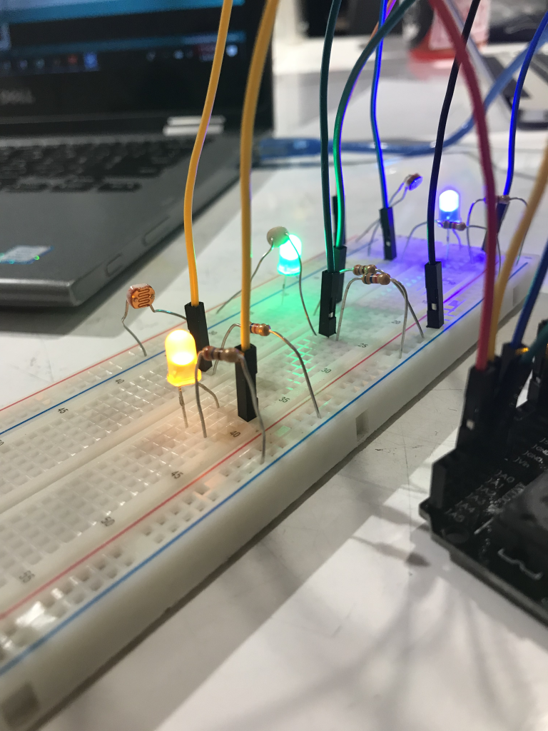
LED and photo cell circuitry assembled separately from speaker and joystick. This was before we added black tape to shield the photocells from other sources of light. Circuit and joystick circuitry assembled. At first we had the joystick movement translate directly to sound.
https://vimeo.com/317853270
At this point our prototype had issues with both the code, and the power source (which we talk about in our discussion), both of which contribute to the LED to sound not working as it should.
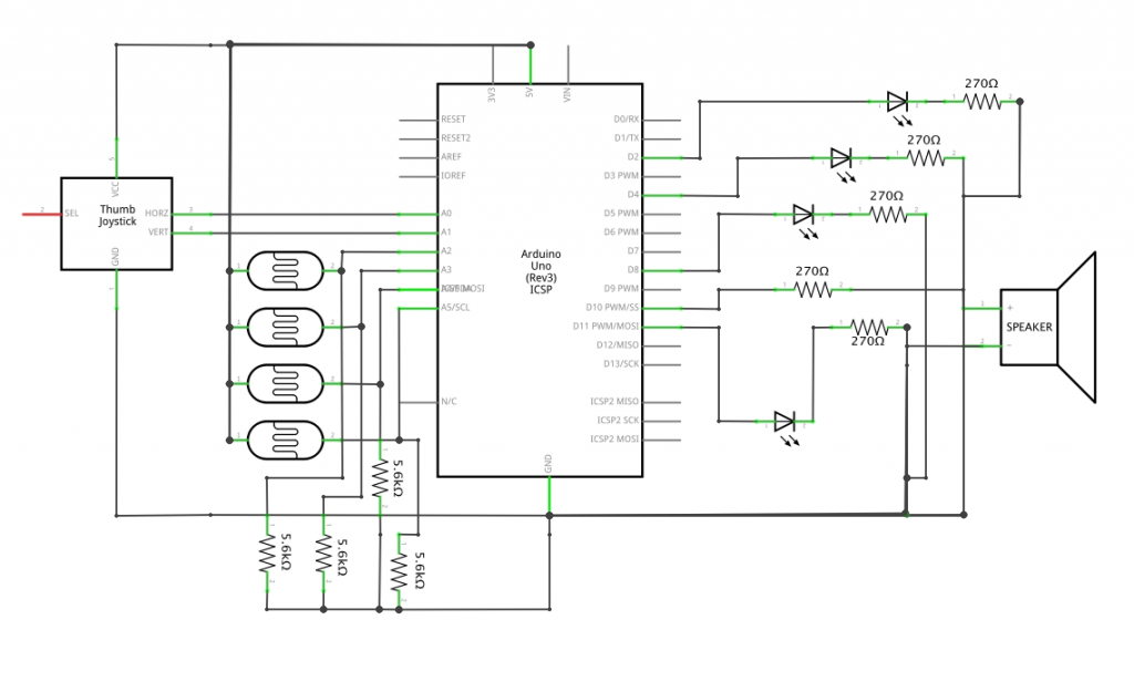
Schematic:
Code:
/*
* Project 1
* Double Transducer: Fidget
* Erin Ryan (eeryan)
* Helen Yu (heleny1)
*
* Description: Code takes in position input from the joystick, translates it to one of four colored LEDs, then takes readings from four photocells to determine which of the four LEDs is on, and plays a note on a speaker based on which LED was lit.
*/
#include "pitches.h"
//joystick variables
int SPEAKPIN = 10 ;
int X_pin = A0 ;
int Y_pin = A1 ;
//photocell variables
const int BLUEPHC = A2 ;
const int GREENPHC = A3 ;
const int YELLOWPHC = A4 ;
const int REDPHC = A5 ;
int redBright ;
int blueBright ;
int yellowBright ;
int greenBright ;
void setup () {
pinMode ( SPEAKPIN , INPUT );
Serial . begin ( 115200 );
pinMode ( BLUEPHC , INPUT );
pinMode ( GREENPHC , INPUT );
pinMode ( YELLOWPHC , INPUT );
pinMode ( REDPHC , INPUT );
pinMode ( 2 , OUTPUT ); //red
pinMode ( 4 , OUTPUT ); //yellow
pinMode ( 8 , OUTPUT ); //green
pinMode ( 11 , OUTPUT ); //blue
}
void loop () {
//joystick test
int xVal = analogRead ( X_pin );
int yVal = analogRead ( Y_pin );
int blueBright ;
int greenBright ;
int yellowBright ;
int redBright ;
blueBright = analogRead ( BLUEPHC );
greenBright = analogRead ( GREENPHC );
yellowBright = analogRead ( YELLOWPHC );
redBright = analogRead ( REDPHC );
//joystick values
Serial . print ( "X-axis: " );
Serial . print ( xVal );
Serial . print ( "\n" );
Serial . print ( "Y-axis: " );
Serial . println ( yVal );
Serial . print ( "\n\n" );
//joystick to LED
//red light on/off
if ((( xVal <= 1023 ) && ( xVal > 511 )) && (( yVal > 511 ) && ( yVal <= 1023 )))
{
digitalWrite ( 2 , HIGH );
}
else {
digitalWrite ( 2 , LOW );
}
//yellow light on/off
if ((( xVal <= 511 ) && ( xVal > 0 )) && (( yVal > 511 ) && ( yVal <= 1023 )))
{
digitalWrite ( 4 , HIGH );
}
else {
digitalWrite ( 4 , LOW );
}
//green light on/off
if ((( xVal <= 511 ) && ( xVal > 0 )) && (( yVal > 0 ) && ( yVal <= 511 )))
{
digitalWrite ( 8 , HIGH );
}
else {
digitalWrite ( 8 , LOW );
}
//blue light on/off
if ((( xVal <= 1023 ) && ( xVal > 511 )) && (( yVal > 0 ) && ( yVal <= 511 )))
{
digitalWrite ( 11 , HIGH );
}
else {
digitalWrite ( 11 , LOW );
}
//LED to sound
String bluestr = "blue " + String ( blueBright );
String greenstr = "green " + String ( greenBright );
String yellowstr = "yellow " + String ( yellowBright );
String redstr = "red " + String ( redBright );
if ( redBright > 400 ){
tone ( SPEAKPIN , NOTE_C1 , 500 );
noTone ( SPEAKPIN );
Serial . println ( redstr );
}
if ( yellowBright > 600 ){
tone ( SPEAKPIN , NOTE_C2 , 500 );
noTone ( SPEAKPIN );
Serial . println ( yellowstr );
}
if ( greenBright > 600 ){
tone ( SPEAKPIN , NOTE_C3 , 500 );
noTone ( SPEAKPIN );
Serial . println ( greenstr );
}
if ( blueBright > 600 ){
tone ( SPEAKPIN , NOTE_C4 , 500 );
noTone ( SPEAKPIN );
Serial . println ( bluestr );
}
} <span class = "com" > /* * Project 1 * Double Transducer: Fidget * Erin Ryan (eeryan) * Helen Yu (heleny1) * * Description: Code takes in position input from the joystick, translates it to one of four colored LEDs, then takes readings from four photocells to determine which of the four LEDs is on, and plays a note on a speaker based on which LED was lit. */ </span><span class = "pln" > </span><span class = "com" > #include</span><span class="pln"> </span><span class="str">"pitches.h"</span><span class="pln"> </span><span class = "com" >//joystick variables</span><span class="pln"> </span><span class = "kwd" > int </span><span class = "pln" > SPEAKPIN </span><span class = "pun" >=</span><span class = "pln" > </span><span class = "lit" > 10 </span><span class = "pun" >;</span><span class = "pln" > </span><span class = "kwd" > int </span><span class = "pln" > X_pin </span><span class = "pun" >=</span><span class = "pln" > A0</span><span class = "pun" >;</span><span class = "pln" > </span><span class = "kwd" > int </span><span class = "pln" > Y_pin </span><span class = "pun" >=</span><span class = "pln" > A1</span><span class = "pun" >;</span><span class = "pln" > </span><span class = "com" >//photocell variables</span><span class="pln"> </span><span class = "kwd" > const </span><span class = "pln" > </span><span class = "kwd" > int </span><span class = "pln" > BLUEPHC </span><span class = "pun" >=</span><span class = "pln" > A2</span><span class = "pun" >;</span><span class = "pln" > </span><span class = "kwd" > const </span><span class = "pln" > </span><span class = "kwd" > int </span><span class = "pln" > GREENPHC </span><span class = "pun" >=</span><span class = "pln" > A3</span><span class = "pun" >;</span><span class = "pln" > </span><span class = "kwd" > const </span><span class = "pln" > </span><span class = "kwd" > int </span><span class = "pln" > YELLOWPHC </span><span class = "pun" >=</span><span class = "pln" > A4</span><span class = "pun" >;</span><span class = "pln" > </span><span class = "kwd" > const </span><span class = "pln" > </span><span class = "kwd" > int </span><span class = "pln" > REDPHC </span><span class = "pun" >=</span><span class = "pln" > A5</span><span class = "pun" >;</span><span class = "pln" > </span><span class = "kwd" > int </span><span class = "pln" > redBright</span><span class = "pun" >;</span><span class = "pln" > </span><span class = "kwd" > int </span><span class = "pln" > blueBright</span><span class = "pun" >;</span><span class = "pln" > </span><span class = "kwd" > int </span><span class = "pln" > yellowBright</span><span class = "pun" >;</span><span class = "pln" > </span><span class = "kwd" > int </span><span class = "pln" > greenBright</span><span class = "pun" >;</span><span class = "pln" > </span><span class = "kwd" > void </span><span class = "pln" > setup</span><span class = "pun" > ( ) </span><span class = "pln" > </span><span class = "pun" > { </span><span class = "pln" > pinMode</span><span class = "pun" > ( </span><span class = "pln" >SPEAKPIN</span><span class = "pun" >,</span><span class = "pln" > INPUT</span><span class = "pun" > ) ;</span><span class = "pln" > </span><span class = "typ" >Serial</span><span class = "pun" >.</span><span class = "kwd" >begin</span><span class = "pun" > ( </span><span class = "lit" > 115200 </span><span class = "pun" > ) ;</span><span class = "pln" > pinMode</span><span class = "pun" > ( </span><span class = "pln" >BLUEPHC</span><span class = "pun" >,</span><span class = "pln" > INPUT</span><span class = "pun" > ) ;</span><span class = "pln" > pinMode</span><span class = "pun" > ( </span><span class = "pln" >GREENPHC</span><span class = "pun" >,</span><span class = "pln" > INPUT</span><span class = "pun" > ) ;</span><span class = "pln" > pinMode</span><span class = "pun" > ( </span><span class = "pln" >YELLOWPHC</span><span class = "pun" >,</span><span class = "pln" > INPUT</span><span class = "pun" > ) ;</span><span class = "pln" > pinMode</span><span class = "pun" > ( </span><span class = "pln" >REDPHC</span><span class = "pun" >,</span><span class = "pln" > INPUT</span><span class = "pun" > ) ;</span><span class = "pln" > pinMode</span><span class = "pun" > ( </span><span class = "lit" > 2 </span><span class = "pun" >,</span><span class = "pln" > OUTPUT</span><span class = "pun" > ) ;</span><span class = "pln" > </span><span class = "com" >//red</span><span class="pln"> pinMode</span><span class = "pun" > ( </span><span class = "lit" > 4 </span><span class = "pun" >,</span><span class = "pln" > OUTPUT</span><span class = "pun" > ) ;</span><span class = "pln" > </span><span class = "com" >//yellow</span><span class="pln"> pinMode</span><span class = "pun" > ( </span><span class = "lit" > 8 </span><span class = "pun" >,</span><span class = "pln" > OUTPUT</span><span class = "pun" > ) ;</span><span class = "pln" > </span><span class = "com" >//green</span><span class="pln"> pinMode</span><span class = "pun" > ( </span><span class = "lit" > 11 </span><span class = "pun" >,</span><span class = "pln" > OUTPUT</span><span class = "pun" > ) ;</span><span class = "pln" > </span><span class = "com" >//blue</span><span class="pln"> </span><span class = "pun" > } </span><span class = "pln" > </span><span class = "kwd" > void </span><span class = "pln" > loop</span><span class = "pun" > ( ) </span><span class = "pln" > </span><span class = "pun" > { </span><span class = "pln" > </span><span class = "com" >//joystick test</span><span class="pln"> </span><span class = "kwd" > int </span><span class = "pln" > xVal </span><span class = "pun" >=</span><span class = "pln" > analogRead</span><span class = "pun" > ( </span><span class = "pln" >X_pin</span><span class = "pun" > ) ;</span><span class = "pln" > </span><span class = "kwd" > int </span><span class = "pln" > yVal </span><span class = "pun" >=</span><span class = "pln" > analogRead</span><span class = "pun" > ( </span><span class = "pln" >Y_pin</span><span class = "pun" > ) ;</span><span class = "pln" > </span><span class = "kwd" > int </span><span class = "pln" > blueBright</span><span class = "pun" >;</span><span class = "pln" > </span><span class = "kwd" > int </span><span class = "pln" > greenBright</span><span class = "pun" >;</span><span class = "pln" > </span><span class = "kwd" > int </span><span class = "pln" > yellowBright</span><span class = "pun" >;</span><span class = "pln" > </span><span class = "kwd" > int </span><span class = "pln" > redBright</span><span class = "pun" >;</span><span class = "pln" > blueBright </span><span class = "pun" >=</span><span class = "pln" > analogRead</span><span class = "pun" > ( </span><span class = "pln" >BLUEPHC</span><span class = "pun" > ) ;</span><span class = "pln" > greenBright </span><span class = "pun" >=</span><span class = "pln" > analogRead</span><span class = "pun" > ( </span><span class = "pln" >GREENPHC</span><span class = "pun" > ) ;</span><span class = "pln" > yellowBright </span><span class = "pun" >=</span><span class = "pln" > analogRead</span><span class = "pun" > ( </span><span class = "pln" >YELLOWPHC</span><span class = "pun" > ) ;</span><span class = "pln" > redBright </span><span class = "pun" >=</span><span class = "pln" > analogRead</span><span class = "pun" > ( </span><span class = "pln" >REDPHC</span><span class = "pun" > ) ;</span><span class = "pln" > </span><span class = "com" >//joystick values</span><span class="pln"> </span><span class = "typ" >Serial</span><span class = "pun" >.</span><span class = "kwd" >print</span><span class = "pun" > ( </span><span class = "str" > "X-axis: " </span><span class = "pun" > ) ;</span><span class = "pln" > </span><span class = "typ" >Serial</span><span class = "pun" >.</span><span class = "kwd" >print</span><span class = "pun" > ( </span><span class = "pln" >xVal</span><span class = "pun" > ) ;</span><span class = "pln" > </span><span class = "typ" >Serial</span><span class = "pun" >.</span><span class = "kwd" >print</span><span class = "pun" > ( </span><span class = "str" > "\n" </span><span class = "pun" > ) ;</span><span class = "pln" > </span><span class = "typ" >Serial</span><span class = "pun" >.</span><span class = "kwd" >print</span><span class = "pun" > ( </span><span class = "str" > "Y-axis: " </span><span class = "pun" > ) ;</span><span class = "pln" > </span><span class = "typ" >Serial</span><span class = "pun" >.</span><span class = "pln" >println</span><span class = "pun" > ( </span><span class = "pln" >yVal</span><span class = "pun" > ) ;</span><span class = "pln" > </span><span class = "typ" >Serial</span><span class = "pun" >.</span><span class = "kwd" >print</span><span class = "pun" > ( </span><span class = "str" > "\n\n" </span><span class = "pun" > ) ;</span><span class = "pln" > </span><span class = "com" >//joystick to LED</span><span class="pln"> </span><span class = "com" >//red light on/off</span><span class="pln"> </span><span class = "kwd" > if </span><span class = "pun" > ( ( ( </span><span class = "pln" >xVal </span><span class = "pun" ><=</span><span class = "pln" > </span><span class = "lit" > 1023 </span><span class = "pun" > ) </span><span class = "pln" > </span><span class = "pun" >&&</span><span class = "pln" > </span><span class = "pun" > ( </span><span class = "pln" >xVal </span><span class = "pun" >></span><span class = "pln" > </span><span class = "lit" > 511 </span><span class = "pun" > ) ) </span><span class = "pln" > </span><span class = "pun" >&&</span><span class = "pln" > </span><span class = "pun" > ( ( </span><span class = "pln" >yVal </span><span class = "pun" >></span><span class = "pln" > </span><span class = "lit" > 511 </span><span class = "pun" > ) </span><span class = "pln" > </span><span class = "pun" >&&</span><span class = "pln" > </span><span class = "pun" > ( </span><span class = "pln" >yVal</span><span class = "pun" ><=</span><span class = "lit" > 1023 </span><span class = "pun" > ) ) ) </span><span class = "pln" > </span><span class = "pun" > { </span><span class = "pln" > digitalWrite</span><span class = "pun" > ( </span><span class = "lit" > 2 </span><span class = "pun" >,</span><span class = "pln" > HIGH</span><span class = "pun" > ) ;</span><span class = "pln" > </span><span class = "pun" > } </span><span class = "pln" > </span><span class = "kwd" > else </span><span class = "pun" > { </span><span class = "pln" > digitalWrite</span><span class = "pun" > ( </span><span class = "lit" > 2 </span><span class = "pun" >,</span><span class = "pln" > LOW</span><span class = "pun" > ) ;</span><span class = "pln" > </span><span class = "pun" > } </span><span class = "pln" > </span><span class = "com" >//yellow light on/off</span><span class="pln"> </span><span class = "kwd" > if </span><span class = "pun" > ( ( ( </span><span class = "pln" >xVal </span><span class = "pun" ><=</span><span class = "pln" > </span><span class = "lit" > 511 </span><span class = "pun" > ) </span><span class = "pln" > </span><span class = "pun" >&&</span><span class = "pln" > </span><span class = "pun" > ( </span><span class = "pln" >xVal </span><span class = "pun" >></span><span class = "pln" > </span><span class = "lit" > 0 </span><span class = "pun" > ) ) </span><span class = "pln" > </span><span class = "pun" >&&</span><span class = "pln" > </span><span class = "pun" > ( ( </span><span class = "pln" >yVal </span><span class = "pun" >></span><span class = "pln" > </span><span class = "lit" > 511 </span><span class = "pun" > ) </span><span class = "pln" > </span><span class = "pun" >&&</span><span class = "pln" > </span><span class = "pun" > ( </span><span class = "pln" >yVal</span><span class = "pun" ><=</span><span class = "lit" > 1023 </span><span class = "pun" > ) ) ) </span><span class = "pln" > </span><span class = "pun" > { </span><span class = "pln" > digitalWrite</span><span class = "pun" > ( </span><span class = "lit" > 4 </span><span class = "pun" >,</span><span class = "pln" > HIGH</span><span class = "pun" > ) ;</span><span class = "pln" > </span><span class = "pun" > } </span><span class = "pln" > </span><span class = "kwd" > else </span><span class = "pun" > { </span><span class = "pln" > digitalWrite</span><span class = "pun" > ( </span><span class = "lit" > 4 </span><span class = "pun" >,</span><span class = "pln" > LOW</span><span class = "pun" > ) ;</span><span class = "pln" > </span><span class = "pun" > } </span><span class = "pln" > </span><span class = "com" >//green light on/off</span><span class="pln"> </span><span class = "kwd" > if </span><span class = "pun" > ( ( ( </span><span class = "pln" >xVal </span><span class = "pun" ><=</span><span class = "pln" > </span><span class = "lit" > 511 </span><span class = "pun" > ) </span><span class = "pln" > </span><span class = "pun" >&&</span><span class = "pln" > </span><span class = "pun" > ( </span><span class = "pln" >xVal </span><span class = "pun" >></span><span class = "pln" > </span><span class = "lit" > 0 </span><span class = "pun" > ) ) </span><span class = "pln" > </span><span class = "pun" >&&</span><span class = "pln" > </span><span class = "pun" > ( ( </span><span class = "pln" >yVal </span><span class = "pun" >></span><span class = "pln" > </span><span class = "lit" > 0 </span><span class = "pun" > ) </span><span class = "pln" > </span><span class = "pun" >&&</span><span class = "pln" > </span><span class = "pun" > ( </span><span class = "pln" >yVal</span><span class = "pun" ><=</span><span class = "lit" > 511 </span><span class = "pun" > ) ) ) </span><span class = "pln" > </span><span class = "pun" > { </span><span class = "pln" > digitalWrite</span><span class = "pun" > ( </span><span class = "lit" > 8 </span><span class = "pun" >,</span><span class = "pln" > HIGH</span><span class = "pun" > ) ;</span><span class = "pln" > </span><span class = "pun" > } </span><span class = "pln" > </span><span class = "kwd" > else </span><span class = "pun" > { </span><span class = "pln" > digitalWrite</span><span class = "pun" > ( </span><span class = "lit" > 8 </span><span class = "pun" >,</span><span class = "pln" > LOW</span><span class = "pun" > ) ;</span><span class = "pln" > </span><span class = "pun" > } </span><span class = "pln" > </span><span class = "com" >//blue light on/off</span><span class="pln"> </span><span class = "kwd" > if </span><span class = "pun" > ( ( ( </span><span class = "pln" >xVal </span><span class = "pun" ><=</span><span class = "pln" > </span><span class = "lit" > 1023 </span><span class = "pun" > ) </span><span class = "pln" > </span><span class = "pun" >&&</span><span class = "pln" > </span><span class = "pun" > ( </span><span class = "pln" >xVal </span><span class = "pun" >></span><span class = "pln" > </span><span class = "lit" > 511 </span><span class = "pun" > ) ) </span><span class = "pln" > </span><span class = "pun" >&&</span><span class = "pln" > </span><span class = "pun" > ( ( </span><span class = "pln" >yVal </span><span class = "pun" >></span><span class = "pln" > </span><span class = "lit" > 0 </span><span class = "pun" > ) </span><span class = "pln" > </span><span class = "pun" >&&</span><span class = "pln" > </span><span class = "pun" > ( </span><span class = "pln" >yVal</span><span class = "pun" ><=</span><span class = "lit" > 511 </span><span class = "pun" > ) ) ) </span><span class = "pln" > </span><span class = "pun" > { </span><span class = "pln" > digitalWrite</span><span class = "pun" > ( </span><span class = "lit" > 11 </span><span class = "pun" >,</span><span class = "pln" > HIGH</span><span class = "pun" > ) ;</span><span class = "pln" > </span><span class = "pun" > } </span><span class = "pln" > </span><span class = "kwd" > else </span><span class = "pun" > { </span><span class = "pln" > digitalWrite</span><span class = "pun" > ( </span><span class = "lit" > 11 </span><span class = "pun" >,</span><span class = "pln" > LOW</span><span class = "pun" > ) ;</span><span class = "pln" > </span><span class = "pun" > } </span><span class = "pln" > </span><span class = "com" >//LED to sound</span><span class="pln"> </span><span class = "typ" >String</span><span class = "pln" > bluestr </span><span class = "pun" >=</span><span class = "pln" > </span><span class = "str" > "blue " </span><span class = "pln" > </span><span class = "pun" >+</span><span class = "pln" > </span><span class = "typ" >String</span><span class = "pun" > ( </span><span class = "pln" >blueBright</span><span class = "pun" > ) ;</span><span class = "pln" > </span><span class = "typ" >String</span><span class = "pln" > greenstr </span><span class = "pun" >=</span><span class = "pln" > </span><span class = "str" > "green " </span><span class = "pln" > </span><span class = "pun" >+</span><span class = "pln" > </span><span class = "typ" >String</span><span class = "pun" > ( </span><span class = "pln" >greenBright</span><span class = "pun" > ) ;</span><span class = "pln" > </span><span class = "typ" >String</span><span class = "pln" > yellowstr </span><span class = "pun" >=</span><span class = "pln" > </span><span class = "str" > "yellow " </span><span class = "pln" > </span><span class = "pun" >+</span><span class = "pln" > </span><span class = "typ" >String</span><span class = "pun" > ( </span><span class = "pln" >yellowBright</span><span class = "pun" > ) ;</span><span class = "pln" > </span><span class = "typ" >String</span><span class = "pln" > redstr </span><span class = "pun" >=</span><span class = "pln" > </span><span class = "str" > "red " </span><span class = "pln" > </span><span class = "pun" >+</span><span class = "pln" > </span><span class = "typ" >String</span><span class = "pun" > ( </span><span class = "pln" >redBright</span><span class = "pun" > ) ;</span><span class = "pln" > </span><span class = "kwd" > if </span><span class = "pln" > </span><span class = "pun" > ( </span><span class = "pln" >redBright </span><span class = "pun" >></span><span class = "pln" > </span><span class = "lit" > 400 </span><span class = "pun" > ) { </span><span class = "pln" > tone</span><span class = "pun" > ( </span><span class = "pln" >SPEAKPIN</span><span class = "pun" >,</span><span class = "pln" > NOTE_C1</span><span class = "pun" >,</span><span class = "pln" > </span><span class = "lit" > 500 </span><span class = "pun" > ) ;</span><span class = "pln" > noTone</span><span class = "pun" > ( </span><span class = "pln" >SPEAKPIN</span><span class = "pun" > ) ;</span><span class = "pln" > </span><span class = "typ" >Serial</span><span class = "pun" >.</span><span class = "pln" >println</span><span class = "pun" > ( </span><span class = "pln" >redstr</span><span class = "pun" > ) ;</span><span class = "pln" > </span><span class = "pun" > } </span><span class = "pln" > </span><span class = "kwd" > if </span><span class = "pln" > </span><span class = "pun" > ( </span><span class = "pln" >yellowBright </span><span class = "pun" >></span><span class = "pln" > </span><span class = "lit" > 600 </span><span class = "pun" > ) { </span><span class = "pln" > tone</span><span class = "pun" > ( </span><span class = "pln" >SPEAKPIN</span><span class = "pun" >,</span><span class = "pln" > NOTE_C2</span><span class = "pun" >,</span><span class = "pln" > </span><span class = "lit" > 500 </span><span class = "pun" > ) ;</span><span class = "pln" > noTone</span><span class = "pun" > ( </span><span class = "pln" >SPEAKPIN</span><span class = "pun" > ) ;</span><span class = "pln" > </span><span class = "typ" >Serial</span><span class = "pun" >.</span><span class = "pln" >println</span><span class = "pun" > ( </span><span class = "pln" >yellowstr</span><span class = "pun" > ) ;</span><span class = "pln" > </span><span class = "pun" > } </span><span class = "pln" > </span><span class = "kwd" > if </span><span class = "pln" > </span><span class = "pun" > ( </span><span class = "pln" >greenBright </span><span class = "pun" >></span><span class = "pln" > </span><span class = "lit" > 600 </span><span class = "pun" > ) { </span><span class = "pln" > tone</span><span class = "pun" > ( </span><span class = "pln" >SPEAKPIN</span><span class = "pun" >,</span><span class = "pln" > NOTE_C3</span><span class = "pun" >,</span><span class = "pln" > </span><span class = "lit" > 500 </span><span class = "pun" > ) ;</span><span class = "pln" > noTone</span><span class = "pun" > ( </span><span class = "pln" >SPEAKPIN</span><span class = "pun" > ) ;</span><span class = "pln" > </span><span class = "typ" >Serial</span><span class = "pun" >.</span><span class = "pln" >println</span><span class = "pun" > ( </span><span class = "pln" >greenstr</span><span class = "pun" > ) ;</span><span class = "pln" > </span><span class = "pun" > } </span><span class = "pln" > </span><span class = "kwd" > if </span><span class = "pln" > </span><span class = "pun" > ( </span><span class = "pln" >blueBright </span><span class = "pun" >></span><span class = "pln" > </span><span class = "lit" > 600 </span><span class = "pun" > ) { </span><span class = "pln" > tone</span><span class = "pun" > ( </span><span class = "pln" >SPEAKPIN</span><span class = "pun" >,</span><span class = "pln" > NOTE_C4</span><span class = "pun" >,</span><span class = "pln" > </span><span class = "lit" > 500 </span><span class = "pun" > ) ;</span><span class = "pln" > noTone</span><span class = "pun" > ( </span><span class = "pln" >SPEAKPIN</span><span class = "pun" > ) ;</span><span class = "pln" > </span><span class = "typ" >Serial</span><span class = "pun" >.</span><span class = "pln" >println</span><span class = "pun" > ( </span><span class = "pln" >bluestr</span><span class = "pun" > ) ;</span><span class = "pln" > </span><span class = "pun" > } </span><span class = "pln" > </span><span class = "pun" > } </span> <span class="com">/*
* Project 1
* Double Transducer: Fidget
* Erin Ryan (eeryan)
* Helen Yu (heleny1)
*
* Description: Code takes in position input from the joystick, translates it to one of four colored LEDs, then takes readings from four photocells to determine which of the four LEDs is on, and plays a note on a speaker based on which LED was lit.
*/</span><span class="pln">
</span><span class="com">#include</span><span class="pln"> </span><span class="str">"pitches.h"</span><span class="pln">
</span><span class="com">//joystick variables</span><span class="pln">
</span><span class="kwd">int</span><span class="pln"> SPEAKPIN </span><span class="pun">=</span><span class="pln"> </span><span class="lit">10</span><span class="pun">;</span><span class="pln">
</span><span class="kwd">int</span><span class="pln"> X_pin </span><span class="pun">=</span><span class="pln"> A0</span><span class="pun">;</span><span class="pln">
</span><span class="kwd">int</span><span class="pln"> Y_pin </span><span class="pun">=</span><span class="pln"> A1</span><span class="pun">;</span><span class="pln">
</span><span class="com">//photocell variables</span><span class="pln">
</span><span class="kwd">const</span><span class="pln"> </span><span class="kwd">int</span><span class="pln"> BLUEPHC </span><span class="pun">=</span><span class="pln"> A2</span><span class="pun">;</span><span class="pln">
</span><span class="kwd">const</span><span class="pln"> </span><span class="kwd">int</span><span class="pln"> GREENPHC </span><span class="pun">=</span><span class="pln"> A3</span><span class="pun">;</span><span class="pln">
</span><span class="kwd">const</span><span class="pln"> </span><span class="kwd">int</span><span class="pln"> YELLOWPHC </span><span class="pun">=</span><span class="pln"> A4</span><span class="pun">;</span><span class="pln">
</span><span class="kwd">const</span><span class="pln"> </span><span class="kwd">int</span><span class="pln"> REDPHC </span><span class="pun">=</span><span class="pln"> A5</span><span class="pun">;</span><span class="pln">
</span><span class="kwd">int</span><span class="pln"> redBright</span><span class="pun">;</span><span class="pln">
</span><span class="kwd">int</span><span class="pln"> blueBright</span><span class="pun">;</span><span class="pln">
</span><span class="kwd">int</span><span class="pln"> yellowBright</span><span class="pun">;</span><span class="pln">
</span><span class="kwd">int</span><span class="pln"> greenBright</span><span class="pun">;</span><span class="pln">
</span><span class="kwd">void</span><span class="pln"> setup</span><span class="pun">()</span><span class="pln"> </span><span class="pun">{</span><span class="pln">
pinMode</span><span class="pun">(</span><span class="pln">SPEAKPIN</span><span class="pun">,</span><span class="pln"> INPUT</span><span class="pun">);</span><span class="pln">
</span><span class="typ">Serial</span><span class="pun">.</span><span class="kwd">begin</span><span class="pun">(</span><span class="lit">115200</span><span class="pun">);</span><span class="pln">
pinMode</span><span class="pun">(</span><span class="pln">BLUEPHC</span><span class="pun">,</span><span class="pln"> INPUT</span><span class="pun">);</span><span class="pln">
pinMode</span><span class="pun">(</span><span class="pln">GREENPHC</span><span class="pun">,</span><span class="pln"> INPUT</span><span class="pun">);</span><span class="pln">
pinMode</span><span class="pun">(</span><span class="pln">YELLOWPHC</span><span class="pun">,</span><span class="pln"> INPUT</span><span class="pun">);</span><span class="pln">
pinMode</span><span class="pun">(</span><span class="pln">REDPHC</span><span class="pun">,</span><span class="pln"> INPUT</span><span class="pun">);</span><span class="pln">
pinMode</span><span class="pun">(</span><span class="lit">2</span><span class="pun">,</span><span class="pln"> OUTPUT</span><span class="pun">);</span><span class="pln"> </span><span class="com">//red</span><span class="pln">
pinMode</span><span class="pun">(</span><span class="lit">4</span><span class="pun">,</span><span class="pln"> OUTPUT</span><span class="pun">);</span><span class="pln"> </span><span class="com">//yellow</span><span class="pln">
pinMode</span><span class="pun">(</span><span class="lit">8</span><span class="pun">,</span><span class="pln"> OUTPUT</span><span class="pun">);</span><span class="pln"> </span><span class="com">//green</span><span class="pln">
pinMode</span><span class="pun">(</span><span class="lit">11</span><span class="pun">,</span><span class="pln"> OUTPUT</span><span class="pun">);</span><span class="pln"> </span><span class="com">//blue</span><span class="pln">
</span><span class="pun">}</span><span class="pln">
</span><span class="kwd">void</span><span class="pln"> loop</span><span class="pun">()</span><span class="pln"> </span><span class="pun">{</span><span class="pln">
</span><span class="com">//joystick test</span><span class="pln">
</span><span class="kwd">int</span><span class="pln"> xVal </span><span class="pun">=</span><span class="pln"> analogRead</span><span class="pun">(</span><span class="pln">X_pin</span><span class="pun">);</span><span class="pln">
</span><span class="kwd">int</span><span class="pln"> yVal </span><span class="pun">=</span><span class="pln"> analogRead</span><span class="pun">(</span><span class="pln">Y_pin</span><span class="pun">);</span><span class="pln">
</span><span class="kwd">int</span><span class="pln"> blueBright</span><span class="pun">;</span><span class="pln">
</span><span class="kwd">int</span><span class="pln"> greenBright</span><span class="pun">;</span><span class="pln">
</span><span class="kwd">int</span><span class="pln"> yellowBright</span><span class="pun">;</span><span class="pln">
</span><span class="kwd">int</span><span class="pln"> redBright</span><span class="pun">;</span><span class="pln">
blueBright </span><span class="pun">=</span><span class="pln"> analogRead</span><span class="pun">(</span><span class="pln">BLUEPHC</span><span class="pun">);</span><span class="pln">
greenBright </span><span class="pun">=</span><span class="pln"> analogRead</span><span class="pun">(</span><span class="pln">GREENPHC</span><span class="pun">);</span><span class="pln">
yellowBright </span><span class="pun">=</span><span class="pln"> analogRead</span><span class="pun">(</span><span class="pln">YELLOWPHC</span><span class="pun">);</span><span class="pln">
redBright </span><span class="pun">=</span><span class="pln"> analogRead</span><span class="pun">(</span><span class="pln">REDPHC</span><span class="pun">);</span><span class="pln">
</span><span class="com">//joystick values</span><span class="pln">
</span><span class="typ">Serial</span><span class="pun">.</span><span class="kwd">print</span><span class="pun">(</span><span class="str">"X-axis: "</span><span class="pun">);</span><span class="pln">
</span><span class="typ">Serial</span><span class="pun">.</span><span class="kwd">print</span><span class="pun">(</span><span class="pln">xVal</span><span class="pun">);</span><span class="pln">
</span><span class="typ">Serial</span><span class="pun">.</span><span class="kwd">print</span><span class="pun">(</span><span class="str">"\n"</span><span class="pun">);</span><span class="pln">
</span><span class="typ">Serial</span><span class="pun">.</span><span class="kwd">print</span><span class="pun">(</span><span class="str">"Y-axis: "</span><span class="pun">);</span><span class="pln">
</span><span class="typ">Serial</span><span class="pun">.</span><span class="pln">println</span><span class="pun">(</span><span class="pln">yVal</span><span class="pun">);</span><span class="pln">
</span><span class="typ">Serial</span><span class="pun">.</span><span class="kwd">print</span><span class="pun">(</span><span class="str">"\n\n"</span><span class="pun">);</span><span class="pln">
</span><span class="com">//joystick to LED</span><span class="pln">
</span><span class="com">//red light on/off</span><span class="pln">
</span><span class="kwd">if</span><span class="pun">(((</span><span class="pln">xVal </span><span class="pun"><=</span><span class="pln"> </span><span class="lit">1023</span><span class="pun">)</span><span class="pln"> </span><span class="pun">&&</span><span class="pln"> </span><span class="pun">(</span><span class="pln">xVal </span><span class="pun">></span><span class="pln"> </span><span class="lit">511</span><span class="pun">))</span><span class="pln"> </span><span class="pun">&&</span><span class="pln"> </span><span class="pun">((</span><span class="pln">yVal </span><span class="pun">></span><span class="pln"> </span><span class="lit">511</span><span class="pun">)</span><span class="pln"> </span><span class="pun">&&</span><span class="pln"> </span><span class="pun">(</span><span class="pln">yVal</span><span class="pun"><=</span><span class="lit">1023</span><span class="pun">)))</span><span class="pln">
</span><span class="pun">{</span><span class="pln">
digitalWrite</span><span class="pun">(</span><span class="lit">2</span><span class="pun">,</span><span class="pln"> HIGH</span><span class="pun">);</span><span class="pln">
</span><span class="pun">}</span><span class="pln">
</span><span class="kwd">else</span><span class="pun">{</span><span class="pln">
digitalWrite</span><span class="pun">(</span><span class="lit">2</span><span class="pun">,</span><span class="pln"> LOW</span><span class="pun">);</span><span class="pln">
</span><span class="pun">}</span><span class="pln">
</span><span class="com">//yellow light on/off</span><span class="pln">
</span><span class="kwd">if</span><span class="pun">(((</span><span class="pln">xVal </span><span class="pun"><=</span><span class="pln"> </span><span class="lit">511</span><span class="pun">)</span><span class="pln"> </span><span class="pun">&&</span><span class="pln"> </span><span class="pun">(</span><span class="pln">xVal </span><span class="pun">></span><span class="pln"> </span><span class="lit">0</span><span class="pun">))</span><span class="pln"> </span><span class="pun">&&</span><span class="pln"> </span><span class="pun">((</span><span class="pln">yVal </span><span class="pun">></span><span class="pln"> </span><span class="lit">511</span><span class="pun">)</span><span class="pln"> </span><span class="pun">&&</span><span class="pln"> </span><span class="pun">(</span><span class="pln">yVal</span><span class="pun"><=</span><span class="lit">1023</span><span class="pun">)))</span><span class="pln">
</span><span class="pun">{</span><span class="pln">
digitalWrite</span><span class="pun">(</span><span class="lit">4</span><span class="pun">,</span><span class="pln"> HIGH</span><span class="pun">);</span><span class="pln">
</span><span class="pun">}</span><span class="pln">
</span><span class="kwd">else</span><span class="pun">{</span><span class="pln">
digitalWrite</span><span class="pun">(</span><span class="lit">4</span><span class="pun">,</span><span class="pln"> LOW</span><span class="pun">);</span><span class="pln">
</span><span class="pun">}</span><span class="pln">
</span><span class="com">//green light on/off</span><span class="pln">
</span><span class="kwd">if</span><span class="pun">(((</span><span class="pln">xVal </span><span class="pun"><=</span><span class="pln"> </span><span class="lit">511</span><span class="pun">)</span><span class="pln"> </span><span class="pun">&&</span><span class="pln"> </span><span class="pun">(</span><span class="pln">xVal </span><span class="pun">></span><span class="pln"> </span><span class="lit">0</span><span class="pun">))</span><span class="pln"> </span><span class="pun">&&</span><span class="pln"> </span><span class="pun">((</span><span class="pln">yVal </span><span class="pun">></span><span class="pln"> </span><span class="lit">0</span><span class="pun">)</span><span class="pln"> </span><span class="pun">&&</span><span class="pln"> </span><span class="pun">(</span><span class="pln">yVal</span><span class="pun"><=</span><span class="lit">511</span><span class="pun">)))</span><span class="pln">
</span><span class="pun">{</span><span class="pln">
digitalWrite</span><span class="pun">(</span><span class="lit">8</span><span class="pun">,</span><span class="pln"> HIGH</span><span class="pun">);</span><span class="pln">
</span><span class="pun">}</span><span class="pln">
</span><span class="kwd">else</span><span class="pun">{</span><span class="pln">
digitalWrite</span><span class="pun">(</span><span class="lit">8</span><span class="pun">,</span><span class="pln"> LOW</span><span class="pun">);</span><span class="pln">
</span><span class="pun">}</span><span class="pln">
</span><span class="com">//blue light on/off</span><span class="pln">
</span><span class="kwd">if</span><span class="pun">(((</span><span class="pln">xVal </span><span class="pun"><=</span><span class="pln"> </span><span class="lit">1023</span><span class="pun">)</span><span class="pln"> </span><span class="pun">&&</span><span class="pln"> </span><span class="pun">(</span><span class="pln">xVal </span><span class="pun">></span><span class="pln"> </span><span class="lit">511</span><span class="pun">))</span><span class="pln"> </span><span class="pun">&&</span><span class="pln"> </span><span class="pun">((</span><span class="pln">yVal </span><span class="pun">></span><span class="pln"> </span><span class="lit">0</span><span class="pun">)</span><span class="pln"> </span><span class="pun">&&</span><span class="pln"> </span><span class="pun">(</span><span class="pln">yVal</span><span class="pun"><=</span><span class="lit">511</span><span class="pun">)))</span><span class="pln">
</span><span class="pun">{</span><span class="pln">
digitalWrite</span><span class="pun">(</span><span class="lit">11</span><span class="pun">,</span><span class="pln"> HIGH</span><span class="pun">);</span><span class="pln">
</span><span class="pun">}</span><span class="pln">
</span><span class="kwd">else</span><span class="pun">{</span><span class="pln">
digitalWrite</span><span class="pun">(</span><span class="lit">11</span><span class="pun">,</span><span class="pln"> LOW</span><span class="pun">);</span><span class="pln">
</span><span class="pun">}</span><span class="pln">
</span><span class="com">//LED to sound</span><span class="pln">
</span><span class="typ">String</span><span class="pln"> bluestr </span><span class="pun">=</span><span class="pln"> </span><span class="str">"blue "</span><span class="pln"> </span><span class="pun">+</span><span class="pln"> </span><span class="typ">String</span><span class="pun">(</span><span class="pln">blueBright</span><span class="pun">);</span><span class="pln">
</span><span class="typ">String</span><span class="pln"> greenstr </span><span class="pun">=</span><span class="pln"> </span><span class="str">"green "</span><span class="pln"> </span><span class="pun">+</span><span class="pln"> </span><span class="typ">String</span><span class="pun">(</span><span class="pln">greenBright</span><span class="pun">);</span><span class="pln">
</span><span class="typ">String</span><span class="pln"> yellowstr </span><span class="pun">=</span><span class="pln"> </span><span class="str">"yellow "</span><span class="pln"> </span><span class="pun">+</span><span class="pln"> </span><span class="typ">String</span><span class="pun">(</span><span class="pln">yellowBright</span><span class="pun">);</span><span class="pln">
</span><span class="typ">String</span><span class="pln"> redstr </span><span class="pun">=</span><span class="pln"> </span><span class="str">"red "</span><span class="pln"> </span><span class="pun">+</span><span class="pln"> </span><span class="typ">String</span><span class="pun">(</span><span class="pln">redBright</span><span class="pun">);</span><span class="pln">
</span><span class="kwd">if</span><span class="pln"> </span><span class="pun">(</span><span class="pln">redBright </span><span class="pun">></span><span class="pln"> </span><span class="lit">400</span><span class="pun">){</span><span class="pln">
tone</span><span class="pun">(</span><span class="pln">SPEAKPIN</span><span class="pun">,</span><span class="pln"> NOTE_C1</span><span class="pun">,</span><span class="pln"> </span><span class="lit">500</span><span class="pun">);</span><span class="pln">
noTone</span><span class="pun">(</span><span class="pln">SPEAKPIN</span><span class="pun">);</span><span class="pln">
</span><span class="typ">Serial</span><span class="pun">.</span><span class="pln">println</span><span class="pun">(</span><span class="pln">redstr</span><span class="pun">);</span><span class="pln">
</span><span class="pun">}</span><span class="pln">
</span><span class="kwd">if</span><span class="pln"> </span><span class="pun">(</span><span class="pln">yellowBright </span><span class="pun">></span><span class="pln"> </span><span class="lit">600</span><span class="pun">){</span><span class="pln">
tone</span><span class="pun">(</span><span class="pln">SPEAKPIN</span><span class="pun">,</span><span class="pln"> NOTE_C2</span><span class="pun">,</span><span class="pln"> </span><span class="lit">500</span><span class="pun">);</span><span class="pln">
noTone</span><span class="pun">(</span><span class="pln">SPEAKPIN</span><span class="pun">);</span><span class="pln">
</span><span class="typ">Serial</span><span class="pun">.</span><span class="pln">println</span><span class="pun">(</span><span class="pln">yellowstr</span><span class="pun">);</span><span class="pln">
</span><span class="pun">}</span><span class="pln">
</span><span class="kwd">if</span><span class="pln"> </span><span class="pun">(</span><span class="pln">greenBright </span><span class="pun">></span><span class="pln"> </span><span class="lit">600</span><span class="pun">){</span><span class="pln">
tone</span><span class="pun">(</span><span class="pln">SPEAKPIN</span><span class="pun">,</span><span class="pln"> NOTE_C3</span><span class="pun">,</span><span class="pln"> </span><span class="lit">500</span><span class="pun">);</span><span class="pln">
noTone</span><span class="pun">(</span><span class="pln">SPEAKPIN</span><span class="pun">);</span><span class="pln">
</span><span class="typ">Serial</span><span class="pun">.</span><span class="pln">println</span><span class="pun">(</span><span class="pln">greenstr</span><span class="pun">);</span><span class="pln">
</span><span class="pun">}</span><span class="pln">
</span><span class="kwd">if</span><span class="pln"> </span><span class="pun">(</span><span class="pln">blueBright </span><span class="pun">></span><span class="pln"> </span><span class="lit">600</span><span class="pun">){</span><span class="pln">
tone</span><span class="pun">(</span><span class="pln">SPEAKPIN</span><span class="pun">,</span><span class="pln"> NOTE_C4</span><span class="pun">,</span><span class="pln"> </span><span class="lit">500</span><span class="pun">);</span><span class="pln">
noTone</span><span class="pun">(</span><span class="pln">SPEAKPIN</span><span class="pun">);</span><span class="pln">
</span><span class="typ">Serial</span><span class="pun">.</span><span class="pln">println</span><span class="pun">(</span><span class="pln">bluestr</span><span class="pun">);</span><span class="pln">
</span><span class="pun">}</span><span class="pln">
</span><span class="pun">}</span>
Discussion:
While working on this double transducer, there were several components that proved to be more challenging than expected. The joystick, which is the first input, does not operate over the cartesian plane like we expected. So, in order to get the LEDs to light up, the directional values of the joystick were mapped and organized to suit our project. In addition to the counterintuitive joystick plane, the joystick wasn’t always centered at its neutral axis. As a result, some LEDs would light up without a physical input from the user. In retrospect, we could resolve this issue by placing a correction factor on the joystick position values. That way, even when the joystick is slightly off center, the device will not read this misalignment as an input from the user.
The different colored LED outputs were easier to put together and program. This part of the transducer consisted of four different colored LEDs and photocells that read the brightness of the LEDs. To control the brightness, black electrical tape was wrapped over the photocells and LEDs. However, because most of the LEDs were covered by the black electrical tape, a physical component of this transducer was hidden. Given the time, we would have installed a more permanent and visible display. Additionally, we think it would have been very interesting to build something that read the color, not the brightness of an LED.
During the first iteration of this double transducer, we discovered that, when plugged into the computer, the speaker produces a tone that is barely audible. To counter this effect, we powered the double transducer with a 5V battery source. However, after running several test trails, we noticed that the light and sound outputs weren’t consistently working the way they had been when plugged into a laptop. When the Arduino is plugged into the computer, the directional input from the joystick translates to the different colored LED almost immediately. This reaction time is shown in the demo video. We had originally attributed this slower reaction time to the runtime of the code, and part of it may have been, as for a while we didn’t have noTone() statements in the code. But even with the updated code, there’s still a very noticeable difference in the functionality of the transducer when it’s using the 5V power source vs a laptop power source.
So, at this point, the cause of this issue is unclear. This functionality issue can be attributed to the loose wiring of the power adapter. It can also mean that the power adapter is not necessarily the best power source for our device. While making this double transducer, we unknowingly made a tradeoff between a better execution and a louder final output. Looking back, it was necessary to change our power source because we did not know the speaker was producing a sound unless we put out ear next to the speaker. Maybe there was a better power solution we could have looked for if we had realized sooner than the crit the issue that the 5V supply was causing.

Comments are closed.