Welcome to the sequence detector safe! The serial output from the Arduino introduces the concept behind the sequence detector safe and allows the user to set a new password using the keypad. Once the password has been set, the user is instructed to turn the screen “towards a friend” to allow them to start taking guesses at the password. The password is only 4 digits longs. The lockbox takes in a stream of digits from the keypad, and uses the last four of the stream as the current guess. Four LED’s are used as hints to the guessing friend, each LED corresponding to a digit. If the first digit is correct, the LED will light up, and then the second will light up indicating if the second is correct. Thus, even if digits 2, 3, 4 are correct, because 1 is not correct, no lights will light up (and same applies for the rest of the digits). Once the passcode has been given correctly, all four LED’s light up and the box will open. As long as the passcode is correct, the box will remain open. If inputting another digit at this time causes the guess to be incorrect, the box will close again.
Testing out the LED matrix component with the keypad. The four-digit 7-segment display component was faulty, so this was used as a substitute instead.
Initial configuration of LED’s and photoresistors to detect on/off. This is before the duct tape was applied to reduce the effect of ambiance on sensor data.
Testing out the use of the servo in opening a cardboard box. A simple mechanical lever (the popsicle stick) was able to suffice. Being able to use this box transformed our project from having a metaphorical “lock” to having a truly physical component.
Putting an art major and an ECE major together proved to be a very interesting combination. Sophia was very focused on having a narrative during the initial ideation, which I (Claire) had a hard time following. I focused more on trying to think of a project that I thought the professor or the class wanted to see, rather than something that I would be excited about. Personally, it was hard for me to imagine what would be impressive or meaningful for other people, as I was having a hard time envisioning myself being satisfied with anything.
The creative process was entirely new to me, and I found it hard to navigate the lax requirements and lack of a real “problem” (which is common in engineering labs and problem sets). However, once we were able to decide what we wanted to do, I felt fairly confident in coding and working with sensors I never have before to make them do what I want them to do. Sophia was extremely helpful in creating a vision for the project and generating overall excitement, while I was more motivated by code development and pulling the project together one component at a time.
I found myself more and more engaged with the project the more time I invested in it, even if we had to take a few detours along the way. Perhaps the biggest obstacle for me is simply starting. I realized that a project that is seemingly simple can have complexity if I want it to. It can be as refined or as crude as I make it, but there is still a lot of room for technical learning. Knowing this, I hope that I will be able to finish projects earlier in the future so I can add little details to it that make it more sophisticated.
I (Sophia) approached this project at first more like one I would find in my Studio classes, where we would start more with a concept under the topic rather than think about the requirements. The fumbling towards a cohesive idea was a small difficulty, but in the end we were able to stamp our foot down on some things and come out with a project that we were both happy with.
Claire was very easy to work with given her much more advanced experience with electrical components which all in all contributed to the brainstorming process quite well. She fiddled mainly with code and electrical components, and I mainly worry-hovered, given that I was more used to doing the virtual side of things and felt oddly about not having that role this time (not bad oddly, just weird oddly).
One thing I would say was difficult was that I was tasked with the mechanical construction of the box based on my more readily available resources in that department. As someone who usually works in the digital realms, mechanical work (hardware, namely) doesn’t come as naturally to me. I had to worry about it breaking after I had fixed it which isn’t so much of a problem in debugging, and also had to worry about material logics such as how to stick things to things. Overall, it was an enjoyable, enlightening, and stressful experience. I hope to do more work in the physical world.
In the future, I think working out a production schedule and roles at the start of the line to make sure that we have more room for mistakes and exploring would help. I think we did well nevertheless this time, however.
Password is correct! All LED’s are on, the LED matrix is smiling, and the box is open.
Close-up of the simple yet effective box-opening technique.
Close-up of the final keypad, LED matrix, and LED lights setup.
The final working project without the serial output. This video showcases the various functionalities of the project: setting a passcode, LED lights giving hints as new guesses are given, the box opening at the correct input, as well as back to closing when the guess is no longer correct.
/*
* Title: Sequence Detector Safe * Made by: Claire Ye, Sophia Cao * Description: Reads numeric input from a keypad, sets a password, and detects a reentry of the password. This is done via LED photocell communication as well as an LED matrix. * Pin mapping: the photocells and LED matrix are hooked to analog pins, and the servo is hooked to a PWM-enabled pin. Everything else is digital. * * */
#include <Keypad.h>
#include <Servo.h>
#include <Wire.h>
#include <Adafruit_GFX.h>
#include "Adafruit_LEDBackpack.h"
const int LED1_PIN = 10 ;
const int LED2_PIN = 11 ;
const int LED3_PIN = 12 ;
const int LED4_PIN = 13 ;
#define STARTUP_TEXT "***\nWelcome to our sequence detector safe!\nSet a passcode to guard your secrets.\nLet your friends freely input numbers to take a guess at your passcode\nHowever, there is a security flaw! D:\nIf your friend guesses at least one of the sequences right, the LED's will light up to show the number correct.\nAnyways, at any point, press # to reset the password.\n***\n"
int valOne , valTwo , valThree , valFour ;
// Keypad
const byte Rows = 4 ;
const byte Cols = 3 ;
char keys [ Rows ][ Cols ]=
{
{ '1' , '2' , '3' },
{ '4' , '5' , '6' },
{ '7' , '8' , '9' },
{ '*' , '0' , '#' }
};
// Smiley face taken from matrix8x8 example code
static const uint8_t PROGMEM
smile_bmp [] =
{ B00111100 ,
B01000010 ,
B10100101 ,
B10000001 ,
B10100101 ,
B10011001 ,
B01000010 ,
B00111100 };
Adafruit_7segment codeDisp = Adafruit_7segment ();
#define PASSCODE_LENGTH 4
byte rowPins [ Rows ] = { 5 , 4 , 3 , 2 }; //connect to the row pinouts of the keypad
byte colPins [ Cols ] = { 8 , 7 , 6 }; //connect to the column pinouts of the keypad
Keypad kpd = Keypad ( makeKeymap ( keys ), rowPins , colPins , Rows , Cols );
int password [ PASSCODE_LENGTH ];
int pass_i = 0 ;
int currentSequence [ PASSCODE_LENGTH ];
int passwordSet ;
bool LED1 , LED2 , LED3 , LED4 ;
Adafruit_8x8matrix matrix = Adafruit_8x8matrix ();
void setup () {
pinMode ( LED1_PIN , OUTPUT );
pinMode ( LED2_PIN , OUTPUT );
pinMode ( LED3_PIN , OUTPUT );
pinMode ( LED4_PIN , OUTPUT );
digitalWrite ( LED1_PIN , LOW );
digitalWrite ( LED2_PIN , LOW );
digitalWrite ( LED3_PIN , LOW );
digitalWrite ( LED4_PIN , LOW );
passwordSet = false ;
for ( int i = 0 ; i < PASSCODE_LENGTH ; i ++) {
currentSequence [ i ] = 0 ;
password [ i ] = 0 ;
}
Serial . begin ( 9600 );
matrix . begin ( 0x70 );
matrix . clear ();
matrix . writeDisplay ();
matrix . setRotation ( 3 );
Serial . println ( STARTUP_TEXT );
pass_set ();
}
/*
* Goes into setting passcode mode or continually allows user to input
* a new sequence
*/
void loop () {
char key = kpd . getKey ();
if ( key ) {
if ( key == '#' ) {
pass_set ();
}
else if ( key == '*' ) {
// do nothing yet
}
else {
update_sequence ( key - '0' );
write_disp ();
update_LED ();
}
Serial . print ( "Current: " );
Serial . print ( currentSequence [ 0 ]);
Serial . print ( currentSequence [ 1 ]);
Serial . print ( currentSequence [ 2 ]);
Serial . print ( currentSequence [ 3 ]);
Serial . println ( "" );
}
}
/*
* Updates the current guess based on input - shifts all other to the left by one and appends last digit.
*/
void update_sequence ( int num ) {
for ( int i = 0 ; i < PASSCODE_LENGTH - 1 ; i ++) {
currentSequence [ i ] = currentSequence [ i + 1 ];
}
currentSequence [ 3 ] = num ;
}
/*
* Sets password
*/
void pass_set (){
passwordSet = true ;
matrix . clear ();
matrix . writeDisplay ();
Serial . println ( "Please set your new password. Turn the screen away so your friend can't see!" );
char key = kpd . getKey ();
pass_i = 0 ;
while ( pass_i < PASSCODE_LENGTH ){
if ( key ){
Serial . println ( key );
password [ pass_i ]=( key ) - '0' ;
pass_i ++;
}
key = kpd . getKey ();
}
Serial . print ( "Passcode is now: " );
Serial . print ( password [ 0 ]);
Serial . print ( password [ 1 ]);
Serial . print ( password [ 2 ]);
Serial . print ( password [ 3 ]);
delay ( 100 );
Serial . println ( "\n\nScreen is self-destructing in 3..." );
delay ( 1000 );
Serial . println ( "2..." );
delay ( 1000 );
Serial . println ( "1..." );
delay ( 1000 );
for ( int i = 0 ; i < 500 ; i ++) {
Serial . println ();
}
Serial . println ( "Try me!" );
}
/*
* Interfaces with LED Matrix to display numbers
*/
void write_disp () {
matrix . clear ();
matrix . drawChar ( 2 , 1 , '0' + currentSequence [ PASSCODE_LENGTH - 1 ], LED_ON , LED_OFF , 1 );
matrix . writeDisplay ();
}
/*
* Interfaces with second Arduino on LED Lights
*/
void update_LED () {
valOne = passwordSet && ( currentSequence [ 0 ] == password [ 0 ]);
valTwo = valOne && ( currentSequence [ 1 ] == password [ 1 ]);
valThree = valTwo && ( currentSequence [ 2 ] == password [ 2 ]);
valFour = valThree && ( currentSequence [ 3 ] == password [ 3 ]);
digitalWrite ( LED1_PIN , valOne );
digitalWrite ( LED2_PIN , valTwo );
digitalWrite ( LED3_PIN , valThree );
digitalWrite ( LED4_PIN , valFour );
if ( valFour ) {
matrix . clear ();
matrix . drawBitmap ( 0 , 0 , smile_bmp , 8 , 8 , LED_ON );
matrix . writeDisplay ();
delay ( 10 );
}
}
/*
* File responsible for interfacing with LED lights and servo
*/
const int LED0_OUT = 2 ;
const int LED1_OUT = 3 ;
const int LED2_OUT = 4 ;
const int LED3_OUT = 5 ;
#include <Servo.h>
const int LED0_IN = 6 ;
const int LED1_IN = 7 ;
const int LED2_IN = 8 ;
const int LED3_IN = 9 ;
const int PHOTO0 = A0 ;
const int PHOTO1 = A1 ;
const int PHOTO2 = A2 ;
const int PHOTO3 = A3 ;
const int SETPOINT = 400 ;
const int BOX_LOCK = 10 ;
const int OPEN = 170 ;
const int CLOSE = 0 ;
int led0_val , led1_val , led2_val , led3_val ;
Servo boxLock ;
void setup () {
// put your setup code here, to run once:
Serial . begin ( 9600 );
pinMode ( LED0_OUT , OUTPUT );
pinMode ( LED1_OUT , OUTPUT );
pinMode ( LED2_OUT , OUTPUT );
pinMode ( LED3_OUT , OUTPUT );
digitalWrite ( LED0_OUT , LOW );
digitalWrite ( LED1_OUT , LOW );
digitalWrite ( LED2_OUT , LOW );
digitalWrite ( LED3_OUT , LOW );
pinMode ( LED0_IN , INPUT );
pinMode ( LED1_IN , INPUT );
pinMode ( LED2_IN , INPUT );
pinMode ( LED3_IN , INPUT );
pinMode ( PHOTO0 , INPUT );
pinMode ( PHOTO1 , INPUT );
pinMode ( PHOTO2 , INPUT );
pinMode ( PHOTO3 , INPUT );
digitalWrite ( LED0_OUT , HIGH );
boxLock . attach ( BOX_LOCK );
}
void loop () {
Serial . println ( "" );
digitalWrite ( LED0_OUT , digitalRead ( LED0_IN ));
digitalWrite ( LED1_OUT , digitalRead ( LED1_IN ));
digitalWrite ( LED2_OUT , digitalRead ( LED2_IN ));
digitalWrite ( LED3_OUT , digitalRead ( LED3_IN ));
led0_val = analogRead ( PHOTO0 ) < SETPOINT ;
led1_val = analogRead ( PHOTO1 ) < SETPOINT ;
led2_val = analogRead ( PHOTO2 ) < SETPOINT ;
led3_val = analogRead ( PHOTO3 ) < SETPOINT ;
/*
Serial.print(analogRead(PHOTO0));
Serial.println("");
Serial.print(analogRead(PHOTO1));
Serial.println("");
Serial.print(analogRead(PHOTO2));
Serial.println("");
Serial.print(analogRead(PHOTO3));
Serial.println("");
*/
if ( led0_val && led1_val && led2_val && led3_val ) {
boxLock . write ( OPEN );
// Serial.println("OPENED!");
}
else {
boxLock . write ( CLOSE );
}
delay ( 200 );
} <span class = "com" > /* * Title: Sequence Detector Safe</span><br><span class="com"> * Made by: Claire Ye, Sophia Cao</span><br><span class="com"> * Description: Reads numeric input from a keypad, sets a password, and detects a reentry of the password. This is done via LED photocell communication as well as an LED matrix. </span><br><span class="com"> * Pin mapping: the photocells and LED matrix are hooked to analog pins, and the servo is hooked to a PWM-enabled pin. Everything else is digital.</span><br><span class="com"> * </span><br><span class="com"> * </span><br><span class="com"> */ </span><span class = "pln" > </span><span class = "com" > #include</span><span class="pln"> </span><span class="str"><Keypad.h></span><span class="pln"> </span><span class = "com" > #include</span><span class="pln"> </span><span class="str"><Servo.h></span><span class="pln"> </span><span class = "com" > #include</span><span class="pln"> </span><span class="str"><Wire.h></span><span class="pln"> </span><span class = "com" > #include</span><span class="pln"> </span><span class="str"><Adafruit_GFX.h></span><span class="pln"> </span><span class = "com" > #include</span><span class="pln"> </span><span class="str">"Adafruit_LEDBackpack.h"</span><span class="pln"> </span><span class = "kwd" > const </span><span class = "pln" > </span><span class = "kwd" > int </span><span class = "pln" > LED1_PIN </span><span class = "pun" >=</span><span class = "pln" > </span><span class = "lit" > 10 </span><span class = "pun" >;</span><span class = "pln" > </span><span class = "kwd" > const </span><span class = "pln" > </span><span class = "kwd" > int </span><span class = "pln" > LED2_PIN </span><span class = "pun" >=</span><span class = "pln" > </span><span class = "lit" > 11 </span><span class = "pun" >;</span><span class = "pln" > </span><span class = "kwd" > const </span><span class = "pln" > </span><span class = "kwd" > int </span><span class = "pln" > LED3_PIN </span><span class = "pun" >=</span><span class = "pln" > </span><span class = "lit" > 12 </span><span class = "pun" >;</span><span class = "pln" > </span><span class = "kwd" > const </span><span class = "pln" > </span><span class = "kwd" > int </span><span class = "pln" > LED4_PIN </span><span class = "pun" >=</span><span class = "pln" > </span><span class = "lit" > 13 </span><span class = "pun" >;</span><span class = "pln" > </span><span class = "com" > #define</span><span class="pln"> STARTUP_TEXT </span><span class="str">"***\nWelcome to our sequence detector safe!\nSet a passcode to guard your secrets.\nLet your friends freely input numbers to take a guess at your passcode\nHowever, there is a security flaw! D:\nIf your friend guesses at least one of the sequences right, the LED's will light up to show the number correct.\nAnyways, at any point, press # to reset the password.\n***\n"</span><span class="pln"> </span><span class = "kwd" > int </span><span class = "pln" > valOne</span><span class = "pun" >,</span><span class = "pln" > valTwo</span><span class = "pun" >,</span><span class = "pln" > valThree</span><span class = "pun" >,</span><span class = "pln" > valFour</span><span class = "pun" >;</span><span class = "pln" > </span><span class = "com" >// Keypad</span><span class="pln"> </span><span class = "kwd" > const </span><span class = "pln" > </span><span class = "kwd" >byte</span><span class = "pln" > </span><span class = "typ" >Rows</span><span class = "pun" >=</span><span class = "pln" > </span><span class = "lit" > 4 </span><span class = "pun" >;</span><span class = "pln" > </span><span class = "kwd" > const </span><span class = "pln" > </span><span class = "kwd" >byte</span><span class = "pln" > </span><span class = "typ" >Cols</span><span class = "pun" >=</span><span class = "pln" > </span><span class = "lit" > 3 </span><span class = "pun" >;</span><span class = "pln" > </span><span class = "kwd" > char </span><span class = "pln" > keys</span><span class = "pun" > [ </span><span class = "typ" >Rows</span><span class = "pun" > ] [ </span><span class = "typ" >Cols</span><span class = "pun" > ] =</span><span class = "pln" > </span><span class = "pun" > { </span><span class = "pln" > </span><span class = "pun" > { </span><span class = "str" > '1' </span><span class = "pun" >,</span><span class = "pln" > </span><span class = "str" > '2' </span><span class = "pun" >,</span><span class = "pln" > </span><span class = "str" > '3' </span><span class = "pun" > } ,</span><span class = "pln" > </span><span class = "pun" > { </span><span class = "str" > '4' </span><span class = "pun" >,</span><span class = "pln" > </span><span class = "str" > '5' </span><span class = "pun" >,</span><span class = "pln" > </span><span class = "str" > '6' </span><span class = "pun" > } ,</span><span class = "pln" > </span><span class = "pun" > { </span><span class = "str" > '7' </span><span class = "pun" >,</span><span class = "pln" > </span><span class = "str" > '8' </span><span class = "pun" >,</span><span class = "pln" > </span><span class = "str" > '9' </span><span class = "pun" > } ,</span><span class = "pln" > </span><span class = "pun" > { </span><span class = "str" > '*' </span><span class = "pun" >,</span><span class = "pln" > </span><span class = "str" > '0' </span><span class = "pun" >,</span><span class = "pln" > </span><span class = "str" > '#' </span><span class = "pun" > } </span><span class = "pln" > </span><span class = "pun" > } ;</span><span class = "pln" > </span><span class = "com" >// Smiley face taken from matrix8x8 example code </span><span class="pln"> </span><span class = "kwd" > static </span><span class = "pln" > </span><span class = "kwd" > const </span><span class = "pln" > </span><span class = "typ" >uint8_t</span><span class = "pln" > PROGMEM smile_bmp</span><span class = "pun" > [ ] </span><span class = "pln" > </span><span class = "pun" >=</span><span class = "pln" > </span><span class = "pun" > { </span><span class = "pln" > B00111100</span><span class = "pun" >,</span><span class = "pln" > B01000010</span><span class = "pun" >,</span><span class = "pln" > B10100101</span><span class = "pun" >,</span><span class = "pln" > B10000001</span><span class = "pun" >,</span><span class = "pln" > B10100101</span><span class = "pun" >,</span><span class = "pln" > B10011001</span><span class = "pun" >,</span><span class = "pln" > B01000010</span><span class = "pun" >,</span><span class = "pln" > B00111100 </span><span class = "pun" > } ;</span><span class = "pln" > </span><span class = "typ" >Adafruit_7segment</span><span class = "pln" > codeDisp </span><span class = "pun" >=</span><span class = "pln" > </span><span class = "typ" >Adafruit_7segment</span><span class = "pun" > ( ) ;</span><span class = "pln" > </span><span class = "com" > #define</span><span class="pln"> PASSCODE_LENGTH </span><span class="lit">4</span><span class="pln"> </span><span class = "kwd" >byte</span><span class = "pln" > rowPins</span><span class = "pun" > [ </span><span class = "typ" >Rows</span><span class = "pun" > ] </span><span class = "pln" > </span><span class = "pun" >=</span><span class = "pln" > </span><span class = "pun" > { </span><span class = "lit" > 5 </span><span class = "pun" >,</span><span class = "pln" > </span><span class = "lit" > 4 </span><span class = "pun" >,</span><span class = "pln" > </span><span class = "lit" > 3 </span><span class = "pun" >,</span><span class = "pln" > </span><span class = "lit" > 2 </span><span class = "pun" > } ;</span><span class = "pln" > </span><span class = "com" >//connect to the row pinouts of the keypad</span><span class="pln"> </span><span class = "kwd" >byte</span><span class = "pln" > colPins</span><span class = "pun" > [ </span><span class = "typ" >Cols</span><span class = "pun" > ] </span><span class = "pln" > </span><span class = "pun" >=</span><span class = "pln" > </span><span class = "pun" > { </span><span class = "lit" > 8 </span><span class = "pun" >,</span><span class = "pln" > </span><span class = "lit" > 7 </span><span class = "pun" >,</span><span class = "pln" > </span><span class = "lit" > 6 </span><span class = "pun" > } ;</span><span class = "pln" > </span><span class = "com" >//connect to the column pinouts of the keypad</span><span class="pln"> </span><span class = "typ" >Keypad</span><span class = "pln" > kpd </span><span class = "pun" >=</span><span class = "pln" > </span><span class = "typ" >Keypad</span><span class = "pun" > ( </span><span class = "pln" > makeKeymap</span><span class = "pun" > ( </span><span class = "pln" >keys</span><span class = "pun" > ) ,</span><span class = "pln" > rowPins</span><span class = "pun" >,</span><span class = "pln" > colPins</span><span class = "pun" >,</span><span class = "pln" > </span><span class = "typ" >Rows</span><span class = "pun" >,</span><span class = "pln" > </span><span class = "typ" >Cols</span><span class = "pln" > </span><span class = "pun" > ) ;</span><span class = "pln" > </span><span class = "kwd" > int </span><span class = "pln" > password</span><span class = "pun" > [ </span><span class = "pln" >PASSCODE_LENGTH</span><span class = "pun" > ] ;</span><span class = "pln" > </span><span class = "kwd" > int </span><span class = "pln" > pass_i</span><span class = "pun" >=</span><span class = "lit" > 0 </span><span class = "pun" >;</span><span class = "pln" > </span><span class = "kwd" > int </span><span class = "pln" > currentSequence</span><span class = "pun" > [ </span><span class = "pln" >PASSCODE_LENGTH</span><span class = "pun" > ] ;</span><span class = "pln" > </span><span class = "kwd" > int </span><span class = "pln" > passwordSet</span><span class = "pun" >;</span><span class = "pln" > </span><span class = "kwd" > bool </span><span class = "pln" > LED1</span><span class = "pun" >,</span><span class = "pln" > LED2</span><span class = "pun" >,</span><span class = "pln" > LED3</span><span class = "pun" >,</span><span class = "pln" > LED4</span><span class = "pun" >;</span><span class = "pln" > </span><span class = "typ" >Adafruit_8x8matrix</span><span class = "pln" > matrix </span><span class = "pun" >=</span><span class = "pln" > </span><span class = "typ" >Adafruit_8x8matrix</span><span class = "pun" > ( ) ;</span><span class = "pln" > </span><span class = "kwd" > void </span><span class = "pln" > setup</span><span class = "pun" > ( ) </span><span class = "pln" > </span><span class = "pun" > { </span><span class = "pln" > pinMode</span><span class = "pun" > ( </span><span class = "pln" >LED1_PIN</span><span class = "pun" >,</span><span class = "pln" > OUTPUT</span><span class = "pun" > ) ;</span><span class = "pln" > pinMode</span><span class = "pun" > ( </span><span class = "pln" >LED2_PIN</span><span class = "pun" >,</span><span class = "pln" > OUTPUT</span><span class = "pun" > ) ;</span><span class = "pln" > pinMode</span><span class = "pun" > ( </span><span class = "pln" >LED3_PIN</span><span class = "pun" >,</span><span class = "pln" > OUTPUT</span><span class = "pun" > ) ;</span><span class = "pln" > pinMode</span><span class = "pun" > ( </span><span class = "pln" >LED4_PIN</span><span class = "pun" >,</span><span class = "pln" > OUTPUT</span><span class = "pun" > ) ;</span><span class = "pln" > digitalWrite</span><span class = "pun" > ( </span><span class = "pln" >LED1_PIN</span><span class = "pun" >,</span><span class = "pln" > LOW</span><span class = "pun" > ) ;</span><span class = "pln" > digitalWrite</span><span class = "pun" > ( </span><span class = "pln" >LED2_PIN</span><span class = "pun" >,</span><span class = "pln" > LOW</span><span class = "pun" > ) ;</span><span class = "pln" > digitalWrite</span><span class = "pun" > ( </span><span class = "pln" >LED3_PIN</span><span class = "pun" >,</span><span class = "pln" > LOW</span><span class = "pun" > ) ;</span><span class = "pln" > digitalWrite</span><span class = "pun" > ( </span><span class = "pln" >LED4_PIN</span><span class = "pun" >,</span><span class = "pln" > LOW</span><span class = "pun" > ) ;</span><span class = "pln" > passwordSet </span><span class = "pun" >=</span><span class = "pln" > </span><span class = "kwd" > false </span><span class = "pun" >;</span><span class = "pln" > </span><span class = "kwd" > for </span><span class = "pln" > </span><span class = "pun" > ( </span><span class = "kwd" > int </span><span class = "pln" > i </span><span class = "pun" >=</span><span class = "pln" > </span><span class = "lit" > 0 </span><span class = "pun" >;</span><span class = "pln" > i </span><span class = "pun" ><</span><span class = "pln" > PASSCODE_LENGTH</span><span class = "pun" >;</span><span class = "pln" > i</span><span class = "pun" >++ ) </span><span class = "pln" > </span><span class = "pun" > { </span><span class = "pln" > currentSequence</span><span class = "pun" > [ </span><span class = "pln" >i</span><span class = "pun" > ] </span><span class = "pln" > </span><span class = "pun" >=</span><span class = "pln" > </span><span class = "lit" > 0 </span><span class = "pun" >;</span><span class = "pln" > password</span><span class = "pun" > [ </span><span class = "pln" >i</span><span class = "pun" > ] </span><span class = "pln" > </span><span class = "pun" >=</span><span class = "pln" > </span><span class = "lit" > 0 </span><span class = "pun" >;</span><span class = "pln" > </span><span class = "pun" > } </span><span class = "pln" > </span><span class = "typ" >Serial</span><span class = "pun" >.</span><span class = "kwd" >begin</span><span class = "pun" > ( </span><span class = "lit" > 9600 </span><span class = "pun" > ) ;</span><span class = "pln" > matrix</span><span class = "pun" >.</span><span class = "kwd" >begin</span><span class = "pun" > ( </span><span class = "lit" > 0x70 </span><span class = "pun" > ) ;</span><span class = "pln" > matrix</span><span class = "pun" >.</span><span class = "pln" >clear</span><span class = "pun" > ( ) ;</span><span class = "pln" > matrix</span><span class = "pun" >.</span><span class = "pln" >writeDisplay</span><span class = "pun" > ( ) ;</span><span class = "pln" > matrix</span><span class = "pun" >.</span><span class = "pln" >setRotation</span><span class = "pun" > ( </span><span class = "lit" > 3 </span><span class = "pun" > ) ;</span><span class = "pln" > </span><span class = "typ" >Serial</span><span class = "pun" >.</span><span class = "pln" >println</span><span class = "pun" > ( </span><span class = "pln" >STARTUP_TEXT</span><span class = "pun" > ) ;</span><span class = "pln" > pass_set</span><span class = "pun" > ( ) ;</span><span class = "pln" > </span><span class = "pun" > } </span><span class = "pln" > </span><span class = "com" > /* * Goes into setting passcode mode or continually allows user to input * a new sequence */ </span><span class = "pln" > </span><span class = "kwd" > void </span><span class = "pln" > loop</span><span class = "pun" > ( ) </span><span class = "pln" > </span><span class = "pun" > { </span><span class = "pln" > </span><span class = "kwd" > char </span><span class = "pln" > key </span><span class = "pun" >=</span><span class = "pln" > kpd</span><span class = "pun" >.</span><span class = "pln" >getKey</span><span class = "pun" > ( ) ;</span><span class = "pln" > </span><span class = "kwd" > if </span><span class = "pln" > </span><span class = "pun" > ( </span><span class = "pln" >key</span><span class = "pun" > ) </span><span class = "pln" > </span><span class = "pun" > { </span><span class = "pln" > </span><span class = "kwd" > if </span><span class = "pln" > </span><span class = "pun" > ( </span><span class = "pln" >key </span><span class = "pun" >==</span><span class = "pln" > </span><span class = "str" > '#' </span><span class = "pun" > ) </span><span class = "pln" > </span><span class = "pun" > { </span><span class = "pln" > pass_set</span><span class = "pun" > ( ) ;</span><span class = "pln" > </span><span class = "pun" > } </span><span class = "pln" > </span><span class = "kwd" > else </span><span class = "pln" > </span><span class = "kwd" > if </span><span class = "pln" > </span><span class = "pun" > ( </span><span class = "pln" >key </span><span class = "pun" >==</span><span class = "pln" > </span><span class = "str" > '*' </span><span class = "pun" > ) </span><span class = "pln" > </span><span class = "pun" > { </span><span class = "pln" > </span><span class = "com" >// do nothing yet </span><span class="pln"> </span><span class = "pun" > } </span><span class = "pln" > </span><span class = "kwd" > else </span><span class = "pln" > </span><span class = "pun" > { </span><span class = "pln" > update_sequence</span><span class = "pun" > ( </span><span class = "pln" >key </span><span class = "pun" >-</span><span class = "pln" > </span><span class = "str" > '0' </span><span class = "pun" > ) ;</span><span class = "pln" > write_disp</span><span class = "pun" > ( ) ;</span><span class = "pln" > update_LED</span><span class = "pun" > ( ) ;</span><span class = "pln" > </span><span class = "pun" > } </span><span class = "pln" > </span><span class = "typ" >Serial</span><span class = "pun" >.</span><span class = "kwd" >print</span><span class = "pun" > ( </span><span class = "str" > "Current: " </span><span class = "pun" > ) ;</span><span class = "pln" > </span><span class = "typ" >Serial</span><span class = "pun" >.</span><span class = "kwd" >print</span><span class = "pun" > ( </span><span class = "pln" >currentSequence</span><span class = "pun" > [ </span><span class = "lit" > 0 </span><span class = "pun" > ] ) ;</span><span class = "pln" > </span><span class = "typ" >Serial</span><span class = "pun" >.</span><span class = "kwd" >print</span><span class = "pun" > ( </span><span class = "pln" >currentSequence</span><span class = "pun" > [ </span><span class = "lit" > 1 </span><span class = "pun" > ] ) ;</span><span class = "pln" > </span><span class = "typ" >Serial</span><span class = "pun" >.</span><span class = "kwd" >print</span><span class = "pun" > ( </span><span class = "pln" >currentSequence</span><span class = "pun" > [ </span><span class = "lit" > 2 </span><span class = "pun" > ] ) ;</span><span class = "pln" > </span><span class = "typ" >Serial</span><span class = "pun" >.</span><span class = "kwd" >print</span><span class = "pun" > ( </span><span class = "pln" >currentSequence</span><span class = "pun" > [ </span><span class = "lit" > 3 </span><span class = "pun" > ] ) ;</span><span class = "pln" > </span><span class = "typ" >Serial</span><span class = "pun" >.</span><span class = "pln" >println</span><span class = "pun" > ( </span><span class = "str" > "" </span><span class = "pun" > ) ;</span><span class = "pln" > </span><span class = "pun" > } </span><span class = "pln" > </span><span class = "pun" > } </span><span class = "pln" > </span><span class = "com" > /* * Updates the current guess based on input - shifts all other to the left by one and appends last digit. */ </span><span class = "pln" > </span><span class = "kwd" > void </span><span class = "pln" > update_sequence</span><span class = "pun" > ( </span><span class = "kwd" > int </span><span class = "pln" > num</span><span class = "pun" > ) </span><span class = "pln" > </span><span class = "pun" > { </span><span class = "pln" > </span><span class = "kwd" > for </span><span class = "pln" > </span><span class = "pun" > ( </span><span class = "kwd" > int </span><span class = "pln" > i </span><span class = "pun" >=</span><span class = "pln" > </span><span class = "lit" > 0 </span><span class = "pun" >;</span><span class = "pln" > i </span><span class = "pun" ><</span><span class = "pln" > PASSCODE_LENGTH </span><span class = "pun" >-</span><span class = "pln" > </span><span class = "lit" > 1 </span><span class = "pun" >;</span><span class = "pln" > i</span><span class = "pun" >++ ) </span><span class = "pln" > </span><span class = "pun" > { </span><span class = "pln" > currentSequence</span><span class = "pun" > [ </span><span class = "pln" >i</span><span class = "pun" > ] </span><span class = "pln" > </span><span class = "pun" >=</span><span class = "pln" > currentSequence</span><span class = "pun" > [ </span><span class = "pln" >i</span><span class = "pun" >+</span><span class = "lit" > 1 </span><span class = "pun" > ] ;</span><span class = "pln" > </span><span class = "pun" > } </span><span class = "pln" > currentSequence</span><span class = "pun" > [ </span><span class = "lit" > 3 </span><span class = "pun" > ] </span><span class = "pln" > </span><span class = "pun" >=</span><span class = "pln" > num</span><span class = "pun" >;</span><span class = "pln" > </span><span class = "pun" > } </span><span class = "pln" > </span><span class = "com" > /* * Sets password */ </span><span class = "pln" > </span><span class = "kwd" > void </span><span class = "pln" > pass_set</span><span class = "pun" > ( ) { </span><span class = "pln" > passwordSet </span><span class = "pun" >=</span><span class = "pln" > </span><span class = "kwd" > true </span><span class = "pun" >;</span><span class = "pln" > matrix</span><span class = "pun" >.</span><span class = "pln" >clear</span><span class = "pun" > ( ) ;</span><span class = "pln" > matrix</span><span class = "pun" >.</span><span class = "pln" >writeDisplay</span><span class = "pun" > ( ) ;</span><span class = "pln" > </span><span class = "typ" >Serial</span><span class = "pun" >.</span><span class = "pln" >println</span><span class = "pun" > ( </span><span class = "str" > "Please set your new password. Turn the screen away so your friend can't see!" </span><span class = "pun" > ) ;</span><span class = "pln" > </span><span class = "kwd" > char </span><span class = "pln" > key </span><span class = "pun" >=</span><span class = "pln" > kpd</span><span class = "pun" >.</span><span class = "pln" >getKey</span><span class = "pun" > ( ) ;</span><span class = "pln" > pass_i</span><span class = "pun" >=</span><span class = "lit" > 0 </span><span class = "pun" >;</span><span class = "pln" > </span><span class = "kwd" > while </span><span class = "pln" > </span><span class = "pun" > ( </span><span class = "pln" >pass_i </span><span class = "pun" ><</span><span class = "pln" > PASSCODE_LENGTH</span><span class = "pun" > ) { </span><span class = "pln" > </span><span class = "kwd" > if </span><span class = "pln" > </span><span class = "pun" > ( </span><span class = "pln" >key</span><span class = "pun" > ) { </span><span class = "pln" > </span><span class = "typ" >Serial</span><span class = "pun" >.</span><span class = "pln" >println</span><span class = "pun" > ( </span><span class = "pln" >key</span><span class = "pun" > ) ;</span><span class = "pln" > password</span><span class = "pun" > [ </span><span class = "pln" >pass_i</span><span class = "pun" > ] = ( </span><span class = "pln" >key</span><span class = "pun" > ) </span><span class = "pln" > </span><span class = "pun" >-</span><span class = "pln" > </span><span class = "str" > '0' </span><span class = "pun" >;</span><span class = "pln" > pass_i</span><span class = "pun" >++;</span><span class = "pln" > </span><span class = "pun" > } </span><span class = "pln" > key </span><span class = "pun" >=</span><span class = "pln" > kpd</span><span class = "pun" >.</span><span class = "pln" >getKey</span><span class = "pun" > ( ) ;</span><span class = "pln" > </span><span class = "pun" > } </span><span class = "pln" > </span><span class = "typ" >Serial</span><span class = "pun" >.</span><span class = "kwd" >print</span><span class = "pun" > ( </span><span class = "str" > "Passcode is now: " </span><span class = "pun" > ) ;</span><span class = "pln" > </span><span class = "typ" >Serial</span><span class = "pun" >.</span><span class = "kwd" >print</span><span class = "pun" > ( </span><span class = "pln" >password</span><span class = "pun" > [ </span><span class = "lit" > 0 </span><span class = "pun" > ] ) ;</span><span class = "pln" > </span><span class = "typ" >Serial</span><span class = "pun" >.</span><span class = "kwd" >print</span><span class = "pun" > ( </span><span class = "pln" >password</span><span class = "pun" > [ </span><span class = "lit" > 1 </span><span class = "pun" > ] ) ;</span><span class = "pln" > </span><span class = "typ" >Serial</span><span class = "pun" >.</span><span class = "kwd" >print</span><span class = "pun" > ( </span><span class = "pln" >password</span><span class = "pun" > [ </span><span class = "lit" > 2 </span><span class = "pun" > ] ) ;</span><span class = "pln" > </span><span class = "typ" >Serial</span><span class = "pun" >.</span><span class = "kwd" >print</span><span class = "pun" > ( </span><span class = "pln" >password</span><span class = "pun" > [ </span><span class = "lit" > 3 </span><span class = "pun" > ] ) ;</span><span class = "pln" > delay</span><span class = "pun" > ( </span><span class = "lit" > 100 </span><span class = "pun" > ) ;</span><span class = "pln" > </span><span class = "typ" >Serial</span><span class = "pun" >.</span><span class = "pln" >println</span><span class = "pun" > ( </span><span class = "str" > "\n\nScreen is self-destructing in 3..." </span><span class = "pun" > ) ;</span><span class = "pln" > delay</span><span class = "pun" > ( </span><span class = "lit" > 1000 </span><span class = "pun" > ) ;</span><span class = "pln" > </span><span class = "typ" >Serial</span><span class = "pun" >.</span><span class = "pln" >println</span><span class = "pun" > ( </span><span class = "str" > "2..." </span><span class = "pun" > ) ;</span><span class = "pln" > delay</span><span class = "pun" > ( </span><span class = "lit" > 1000 </span><span class = "pun" > ) ;</span><span class = "pln" > </span><span class = "typ" >Serial</span><span class = "pun" >.</span><span class = "pln" >println</span><span class = "pun" > ( </span><span class = "str" > "1..." </span><span class = "pun" > ) ;</span><span class = "pln" > delay</span><span class = "pun" > ( </span><span class = "lit" > 1000 </span><span class = "pun" > ) ;</span><span class = "pln" > </span><span class = "kwd" > for </span><span class = "pln" > </span><span class = "pun" > ( </span><span class = "kwd" > int </span><span class = "pln" > i </span><span class = "pun" >=</span><span class = "pln" > </span><span class = "lit" > 0 </span><span class = "pun" >;</span><span class = "pln" > i </span><span class = "pun" ><</span><span class = "pln" > </span><span class = "lit" > 500 </span><span class = "pun" >;</span><span class = "pln" > i</span><span class = "pun" >++ ) </span><span class = "pln" > </span><span class = "pun" > { </span><span class = "pln" > </span><span class = "typ" >Serial</span><span class = "pun" >.</span><span class = "pln" >println</span><span class = "pun" > ( ) ;</span><span class = "pln" > </span><span class = "pun" > } </span><span class = "pln" > </span><span class = "typ" >Serial</span><span class = "pun" >.</span><span class = "pln" >println</span><span class = "pun" > ( </span><span class = "str" > "Try me!" </span><span class = "pun" > ) ;</span><span class = "pln" > </span><span class = "pun" > } </span><span class = "pln" > </span><span class = "com" > /* * Interfaces with LED Matrix to display numbers */ </span><span class = "pln" > </span><span class = "kwd" > void </span><span class = "pln" > write_disp</span><span class = "pun" > ( ) </span><span class = "pln" > </span><span class = "pun" > { </span><span class = "pln" > matrix</span><span class = "pun" >.</span><span class = "pln" >clear</span><span class = "pun" > ( ) ;</span><span class = "pln" > matrix</span><span class = "pun" >.</span><span class = "pln" >drawChar</span><span class = "pun" > ( </span><span class = "lit" > 2 </span><span class = "pun" >,</span><span class = "pln" > </span><span class = "lit" > 1 </span><span class = "pun" >,</span><span class = "pln" > </span><span class = "str" > '0' </span><span class = "pln" > </span><span class = "pun" >+</span><span class = "pln" > currentSequence</span><span class = "pun" > [ </span><span class = "pln" >PASSCODE_LENGTH</span><span class = "pun" >-</span><span class = "lit" > 1 </span><span class = "pun" > ] ,</span><span class = "pln" > LED_ON</span><span class = "pun" >,</span><span class = "pln" > LED_OFF</span><span class = "pun" >,</span><span class = "pln" > </span><span class = "lit" > 1 </span><span class = "pun" > ) ;</span><span class = "pln" > matrix</span><span class = "pun" >.</span><span class = "pln" >writeDisplay</span><span class = "pun" > ( ) ;</span><span class = "pln" > </span><span class = "pun" > } </span><span class = "pln" > </span><span class = "com" > /* * Interfaces with second Arduino on LED Lights */ </span><span class = "pln" > </span><span class = "kwd" > void </span><span class = "pln" > update_LED</span><span class = "pun" > ( ) </span><span class = "pln" > </span><span class = "pun" > { </span><span class = "pln" > valOne </span><span class = "pun" >=</span><span class = "pln" > passwordSet </span><span class = "pun" >&&</span><span class = "pln" > </span><span class = "pun" > ( </span><span class = "pln" >currentSequence</span><span class = "pun" > [ </span><span class = "lit" > 0 </span><span class = "pun" > ] </span><span class = "pln" > </span><span class = "pun" >==</span><span class = "pln" > password</span><span class = "pun" > [ </span><span class = "lit" > 0 </span><span class = "pun" > ] ) ;</span><span class = "pln" > valTwo </span><span class = "pun" >=</span><span class = "pln" > valOne </span><span class = "pun" >&&</span><span class = "pln" > </span><span class = "pun" > ( </span><span class = "pln" >currentSequence</span><span class = "pun" > [ </span><span class = "lit" > 1 </span><span class = "pun" > ] </span><span class = "pln" > </span><span class = "pun" >==</span><span class = "pln" > password</span><span class = "pun" > [ </span><span class = "lit" > 1 </span><span class = "pun" > ] ) ;</span><span class = "pln" > valThree </span><span class = "pun" >=</span><span class = "pln" > valTwo </span><span class = "pun" >&&</span><span class = "pln" > </span><span class = "pun" > ( </span><span class = "pln" >currentSequence</span><span class = "pun" > [ </span><span class = "lit" > 2 </span><span class = "pun" > ] </span><span class = "pln" > </span><span class = "pun" >==</span><span class = "pln" > password</span><span class = "pun" > [ </span><span class = "lit" > 2 </span><span class = "pun" > ] ) ;</span><span class = "pln" > valFour </span><span class = "pun" >=</span><span class = "pln" > valThree </span><span class = "pun" >&&</span><span class = "pln" > </span><span class = "pun" > ( </span><span class = "pln" >currentSequence</span><span class = "pun" > [ </span><span class = "lit" > 3 </span><span class = "pun" > ] </span><span class = "pln" > </span><span class = "pun" >==</span><span class = "pln" > password</span><span class = "pun" > [ </span><span class = "lit" > 3 </span><span class = "pun" > ] ) ;</span><span class = "pln" > digitalWrite</span><span class = "pun" > ( </span><span class = "pln" >LED1_PIN</span><span class = "pun" >,</span><span class = "pln" > valOne</span><span class = "pun" > ) ;</span><span class = "pln" > digitalWrite</span><span class = "pun" > ( </span><span class = "pln" >LED2_PIN</span><span class = "pun" >,</span><span class = "pln" > valTwo</span><span class = "pun" > ) ;</span><span class = "pln" > digitalWrite</span><span class = "pun" > ( </span><span class = "pln" >LED3_PIN</span><span class = "pun" >,</span><span class = "pln" > valThree</span><span class = "pun" > ) ;</span><span class = "pln" > digitalWrite</span><span class = "pun" > ( </span><span class = "pln" >LED4_PIN</span><span class = "pun" >,</span><span class = "pln" > valFour</span><span class = "pun" > ) ;</span><span class = "pln" > </span><span class = "kwd" > if </span><span class = "pln" > </span><span class = "pun" > ( </span><span class = "pln" >valFour</span><span class = "pun" > ) </span><span class = "pln" > </span><span class = "pun" > { </span><span class = "pln" > matrix</span><span class = "pun" >.</span><span class = "pln" >clear</span><span class = "pun" > ( ) ;</span><span class = "pln" > matrix</span><span class = "pun" >.</span><span class = "pln" >drawBitmap</span><span class = "pun" > ( </span><span class = "lit" > 0 </span><span class = "pun" >,</span><span class = "lit" > 0 </span><span class = "pun" >,</span><span class = "pln" > smile_bmp</span><span class = "pun" >,</span><span class = "pln" > </span><span class = "lit" > 8 </span><span class = "pun" >,</span><span class = "pln" > </span><span class = "lit" > 8 </span><span class = "pun" >,</span><span class = "pln" > LED_ON</span><span class = "pun" > ) ;</span><span class = "pln" > matrix</span><span class = "pun" >.</span><span class = "pln" >writeDisplay</span><span class = "pun" > ( ) ;</span><span class = "pln" > delay</span><span class = "pun" > ( </span><span class = "lit" > 10 </span><span class = "pun" > ) ;</span><span class = "pln" > </span><span class = "pun" > } </span><span class = "pln" > </span><span class = "pun" > } </span><span class = "pln" > </span><span class = "com" > /* * File responsible for interfacing with LED lights and servo */ </span><span class = "pln" > </span><span class = "kwd" > const </span><span class = "pln" > </span><span class = "kwd" > int </span><span class = "pln" > LED0_OUT </span><span class = "pun" >=</span><span class = "pln" > </span><span class = "lit" > 2 </span><span class = "pun" >;</span><span class = "pln" > </span><span class = "kwd" > const </span><span class = "pln" > </span><span class = "kwd" > int </span><span class = "pln" > LED1_OUT </span><span class = "pun" >=</span><span class = "pln" > </span><span class = "lit" > 3 </span><span class = "pun" >;</span><span class = "pln" > </span><span class = "kwd" > const </span><span class = "pln" > </span><span class = "kwd" > int </span><span class = "pln" > LED2_OUT </span><span class = "pun" >=</span><span class = "pln" > </span><span class = "lit" > 4 </span><span class = "pun" >;</span><span class = "pln" > </span><span class = "kwd" > const </span><span class = "pln" > </span><span class = "kwd" > int </span><span class = "pln" > LED3_OUT </span><span class = "pun" >=</span><span class = "pln" > </span><span class = "lit" > 5 </span><span class = "pun" >;</span><span class = "pln" > </span><span class = "com" > #include</span><span class="pln"> </span><span class="str"><Servo.h></span><span class="pln"> </span><span class = "kwd" > const </span><span class = "pln" > </span><span class = "kwd" > int </span><span class = "pln" > LED0_IN </span><span class = "pun" >=</span><span class = "pln" > </span><span class = "lit" > 6 </span><span class = "pun" >;</span><span class = "pln" > </span><span class = "kwd" > const </span><span class = "pln" > </span><span class = "kwd" > int </span><span class = "pln" > LED1_IN </span><span class = "pun" >=</span><span class = "pln" > </span><span class = "lit" > 7 </span><span class = "pun" >;</span><span class = "pln" > </span><span class = "kwd" > const </span><span class = "pln" > </span><span class = "kwd" > int </span><span class = "pln" > LED2_IN </span><span class = "pun" >=</span><span class = "pln" > </span><span class = "lit" > 8 </span><span class = "pun" >;</span><span class = "pln" > </span><span class = "kwd" > const </span><span class = "pln" > </span><span class = "kwd" > int </span><span class = "pln" > LED3_IN </span><span class = "pun" >=</span><span class = "pln" > </span><span class = "lit" > 9 </span><span class = "pun" >;</span><span class = "pln" > </span><span class = "kwd" > const </span><span class = "pln" > </span><span class = "kwd" > int </span><span class = "pln" > PHOTO0 </span><span class = "pun" >=</span><span class = "pln" > A0</span><span class = "pun" >;</span><span class = "pln" > </span><span class = "kwd" > const </span><span class = "pln" > </span><span class = "kwd" > int </span><span class = "pln" > PHOTO1 </span><span class = "pun" >=</span><span class = "pln" > A1</span><span class = "pun" >;</span><span class = "pln" > </span><span class = "kwd" > const </span><span class = "pln" > </span><span class = "kwd" > int </span><span class = "pln" > PHOTO2 </span><span class = "pun" >=</span><span class = "pln" > A2</span><span class = "pun" >;</span><span class = "pln" > </span><span class = "kwd" > const </span><span class = "pln" > </span><span class = "kwd" > int </span><span class = "pln" > PHOTO3 </span><span class = "pun" >=</span><span class = "pln" > A3</span><span class = "pun" >;</span><span class = "pln" > </span><span class = "kwd" > const </span><span class = "pln" > </span><span class = "kwd" > int </span><span class = "pln" > SETPOINT </span><span class = "pun" >=</span><span class = "pln" > </span><span class = "lit" > 400 </span><span class = "pun" >;</span><span class = "pln" > </span><span class = "kwd" > const </span><span class = "pln" > </span><span class = "kwd" > int </span><span class = "pln" > BOX_LOCK </span><span class = "pun" >=</span><span class = "pln" > </span><span class = "lit" > 10 </span><span class = "pun" >;</span><span class = "pln" > </span><span class = "kwd" > const </span><span class = "pln" > </span><span class = "kwd" > int </span><span class = "pln" > OPEN </span><span class = "pun" >=</span><span class = "pln" > </span><span class = "lit" > 170 </span><span class = "pun" >;</span><span class = "pln" > </span><span class = "kwd" > const </span><span class = "pln" > </span><span class = "kwd" > int </span><span class = "pln" > CLOSE </span><span class = "pun" >=</span><span class = "pln" > </span><span class = "lit" > 0 </span><span class = "pun" >;</span><span class = "pln" > </span><span class = "kwd" > int </span><span class = "pln" > led0_val</span><span class = "pun" >,</span><span class = "pln" > led1_val</span><span class = "pun" >,</span><span class = "pln" > led2_val</span><span class = "pun" >,</span><span class = "pln" > led3_val</span><span class = "pun" >;</span><span class = "pln" > </span><span class = "typ" >Servo</span><span class = "pln" > boxLock</span><span class = "pun" >;</span><span class = "pln" > </span><span class = "kwd" > void </span><span class = "pln" > setup</span><span class = "pun" > ( ) </span><span class = "pln" > </span><span class = "pun" > { </span><span class = "pln" > </span><span class = "com" >// put your setup code here, to run once:</span><span class="pln"> </span><span class = "typ" >Serial</span><span class = "pun" >.</span><span class = "kwd" >begin</span><span class = "pun" > ( </span><span class = "lit" > 9600 </span><span class = "pun" > ) ;</span><span class = "pln" > pinMode</span><span class = "pun" > ( </span><span class = "pln" >LED0_OUT</span><span class = "pun" >,</span><span class = "pln" > OUTPUT</span><span class = "pun" > ) ;</span><span class = "pln" > pinMode</span><span class = "pun" > ( </span><span class = "pln" >LED1_OUT</span><span class = "pun" >,</span><span class = "pln" > OUTPUT</span><span class = "pun" > ) ;</span><span class = "pln" > pinMode</span><span class = "pun" > ( </span><span class = "pln" >LED2_OUT</span><span class = "pun" >,</span><span class = "pln" > OUTPUT</span><span class = "pun" > ) ;</span><span class = "pln" > pinMode</span><span class = "pun" > ( </span><span class = "pln" >LED3_OUT</span><span class = "pun" >,</span><span class = "pln" > OUTPUT</span><span class = "pun" > ) ;</span><span class = "pln" > digitalWrite</span><span class = "pun" > ( </span><span class = "pln" >LED0_OUT</span><span class = "pun" >,</span><span class = "pln" > LOW</span><span class = "pun" > ) ;</span><span class = "pln" > digitalWrite</span><span class = "pun" > ( </span><span class = "pln" >LED1_OUT</span><span class = "pun" >,</span><span class = "pln" > LOW</span><span class = "pun" > ) ;</span><span class = "pln" > digitalWrite</span><span class = "pun" > ( </span><span class = "pln" >LED2_OUT</span><span class = "pun" >,</span><span class = "pln" > LOW</span><span class = "pun" > ) ;</span><span class = "pln" > digitalWrite</span><span class = "pun" > ( </span><span class = "pln" >LED3_OUT</span><span class = "pun" >,</span><span class = "pln" > LOW</span><span class = "pun" > ) ;</span><span class = "pln" > pinMode</span><span class = "pun" > ( </span><span class = "pln" >LED0_IN</span><span class = "pun" >,</span><span class = "pln" > INPUT</span><span class = "pun" > ) ;</span><span class = "pln" > pinMode</span><span class = "pun" > ( </span><span class = "pln" >LED1_IN</span><span class = "pun" >,</span><span class = "pln" > INPUT</span><span class = "pun" > ) ;</span><span class = "pln" > pinMode</span><span class = "pun" > ( </span><span class = "pln" >LED2_IN</span><span class = "pun" >,</span><span class = "pln" > INPUT</span><span class = "pun" > ) ;</span><span class = "pln" > pinMode</span><span class = "pun" > ( </span><span class = "pln" >LED3_IN</span><span class = "pun" >,</span><span class = "pln" > INPUT</span><span class = "pun" > ) ;</span><span class = "pln" > pinMode</span><span class = "pun" > ( </span><span class = "pln" >PHOTO0</span><span class = "pun" >,</span><span class = "pln" > INPUT</span><span class = "pun" > ) ;</span><span class = "pln" > pinMode</span><span class = "pun" > ( </span><span class = "pln" >PHOTO1</span><span class = "pun" >,</span><span class = "pln" > INPUT</span><span class = "pun" > ) ;</span><span class = "pln" > pinMode</span><span class = "pun" > ( </span><span class = "pln" >PHOTO2</span><span class = "pun" >,</span><span class = "pln" > INPUT</span><span class = "pun" > ) ;</span><span class = "pln" > pinMode</span><span class = "pun" > ( </span><span class = "pln" >PHOTO3</span><span class = "pun" >,</span><span class = "pln" > INPUT</span><span class = "pun" > ) ;</span><span class = "pln" > digitalWrite</span><span class = "pun" > ( </span><span class = "pln" >LED0_OUT</span><span class = "pun" >,</span><span class = "pln" > HIGH</span><span class = "pun" > ) ;</span><span class = "pln" > boxLock</span><span class = "pun" >.</span><span class = "pln" >attach</span><span class = "pun" > ( </span><span class = "pln" >BOX_LOCK</span><span class = "pun" > ) ;</span><span class = "pln" > </span><span class = "pun" > } </span><span class = "pln" > </span><span class = "kwd" > void </span><span class = "pln" > loop</span><span class = "pun" > ( ) </span><span class = "pln" > </span><span class = "pun" > { </span><span class = "pln" > </span><span class = "typ" >Serial</span><span class = "pun" >.</span><span class = "pln" >println</span><span class = "pun" > ( </span><span class = "str" > "" </span><span class = "pun" > ) ;</span><span class = "pln" > digitalWrite</span><span class = "pun" > ( </span><span class = "pln" >LED0_OUT</span><span class = "pun" >,</span><span class = "pln" > digitalRead</span><span class = "pun" > ( </span><span class = "pln" >LED0_IN</span><span class = "pun" > ) ) ;</span><span class = "pln" > digitalWrite</span><span class = "pun" > ( </span><span class = "pln" >LED1_OUT</span><span class = "pun" >,</span><span class = "pln" > digitalRead</span><span class = "pun" > ( </span><span class = "pln" >LED1_IN</span><span class = "pun" > ) ) ;</span><span class = "pln" > digitalWrite</span><span class = "pun" > ( </span><span class = "pln" >LED2_OUT</span><span class = "pun" >,</span><span class = "pln" > digitalRead</span><span class = "pun" > ( </span><span class = "pln" >LED2_IN</span><span class = "pun" > ) ) ;</span><span class = "pln" > digitalWrite</span><span class = "pun" > ( </span><span class = "pln" >LED3_OUT</span><span class = "pun" >,</span><span class = "pln" > digitalRead</span><span class = "pun" > ( </span><span class = "pln" >LED3_IN</span><span class = "pun" > ) ) ;</span><span class = "pln" > led0_val </span><span class = "pun" >=</span><span class = "pln" > analogRead</span><span class = "pun" > ( </span><span class = "pln" >PHOTO0</span><span class = "pun" > ) </span><span class = "pln" > </span><span class = "pun" ><</span><span class = "pln" > SETPOINT</span><span class = "pun" >;</span><span class = "pln" > led1_val </span><span class = "pun" >=</span><span class = "pln" > analogRead</span><span class = "pun" > ( </span><span class = "pln" >PHOTO1</span><span class = "pun" > ) </span><span class = "pln" > </span><span class = "pun" ><</span><span class = "pln" > SETPOINT</span><span class = "pun" >;</span><span class = "pln" > led2_val </span><span class = "pun" >=</span><span class = "pln" > analogRead</span><span class = "pun" > ( </span><span class = "pln" >PHOTO2</span><span class = "pun" > ) </span><span class = "pln" > </span><span class = "pun" ><</span><span class = "pln" > SETPOINT</span><span class = "pun" >;</span><span class = "pln" > led3_val </span><span class = "pun" >=</span><span class = "pln" > analogRead</span><span class = "pun" > ( </span><span class = "pln" >PHOTO3</span><span class = "pun" > ) </span><span class = "pln" > </span><span class = "pun" ><</span><span class = "pln" > SETPOINT</span><span class = "pun" >;</span><span class = "pln" > </span><span class = "com" > /* Serial.print(analogRead(PHOTO0)); Serial.println(""); Serial.print(analogRead(PHOTO1)); Serial.println(""); Serial.print(analogRead(PHOTO2)); Serial.println(""); Serial.print(analogRead(PHOTO3)); Serial.println(""); */ </span><span class = "pln" > </span><span class = "kwd" > if </span><span class = "pln" > </span><span class = "pun" > ( </span><span class = "pln" >led0_val </span><span class = "pun" >&&</span><span class = "pln" > led1_val </span><span class = "pun" >&&</span><span class = "pln" > led2_val </span><span class = "pun" >&&</span><span class = "pln" > led3_val</span><span class = "pun" > ) </span><span class = "pln" > </span><span class = "pun" > { </span><span class = "pln" > boxLock</span><span class = "pun" >.</span><span class = "pln" >write</span><span class = "pun" > ( </span><span class = "pln" >OPEN</span><span class = "pun" > ) ;</span><span class = "pln" > </span><span class = "com" >// Serial.println("OPENED!"); </span><span class="pln"> </span><span class = "pun" > } </span><span class = "pln" > </span><span class = "kwd" > else </span><span class = "pln" > </span><span class = "pun" > { </span><span class = "pln" > boxLock</span><span class = "pun" >.</span><span class = "pln" >write</span><span class = "pun" > ( </span><span class = "pln" >CLOSE</span><span class = "pun" > ) ;</span><span class = "pln" > </span><span class = "pun" > } </span><span class = "pln" > delay</span><span class = "pun" > ( </span><span class = "lit" > 200 </span><span class = "pun" > ) ;</span><span class = "pln" > </span><span class = "pun" > } </span> <span class="com">/*
* Title: Sequence Detector Safe</span><br><span class="com"> * Made by: Claire Ye, Sophia Cao</span><br><span class="com"> * Description: Reads numeric input from a keypad, sets a password, and detects a reentry of the password. This is done via LED photocell communication as well as an LED matrix. </span><br><span class="com"> * Pin mapping: the photocells and LED matrix are hooked to analog pins, and the servo is hooked to a PWM-enabled pin. Everything else is digital.</span><br><span class="com"> * </span><br><span class="com"> * </span><br><span class="com"> */</span><span class="pln">
</span><span class="com">#include</span><span class="pln"> </span><span class="str"><Keypad.h></span><span class="pln">
</span><span class="com">#include</span><span class="pln"> </span><span class="str"><Servo.h></span><span class="pln">
</span><span class="com">#include</span><span class="pln"> </span><span class="str"><Wire.h></span><span class="pln">
</span><span class="com">#include</span><span class="pln"> </span><span class="str"><Adafruit_GFX.h></span><span class="pln">
</span><span class="com">#include</span><span class="pln"> </span><span class="str">"Adafruit_LEDBackpack.h"</span><span class="pln">
</span><span class="kwd">const</span><span class="pln"> </span><span class="kwd">int</span><span class="pln"> LED1_PIN </span><span class="pun">=</span><span class="pln"> </span><span class="lit">10</span><span class="pun">;</span><span class="pln">
</span><span class="kwd">const</span><span class="pln"> </span><span class="kwd">int</span><span class="pln"> LED2_PIN </span><span class="pun">=</span><span class="pln"> </span><span class="lit">11</span><span class="pun">;</span><span class="pln">
</span><span class="kwd">const</span><span class="pln"> </span><span class="kwd">int</span><span class="pln"> LED3_PIN </span><span class="pun">=</span><span class="pln"> </span><span class="lit">12</span><span class="pun">;</span><span class="pln">
</span><span class="kwd">const</span><span class="pln"> </span><span class="kwd">int</span><span class="pln"> LED4_PIN </span><span class="pun">=</span><span class="pln"> </span><span class="lit">13</span><span class="pun">;</span><span class="pln">
</span><span class="com">#define</span><span class="pln"> STARTUP_TEXT </span><span class="str">"***\nWelcome to our sequence detector safe!\nSet a passcode to guard your secrets.\nLet your friends freely input numbers to take a guess at your passcode\nHowever, there is a security flaw! D:\nIf your friend guesses at least one of the sequences right, the LED's will light up to show the number correct.\nAnyways, at any point, press # to reset the password.\n***\n"</span><span class="pln">
</span><span class="kwd">int</span><span class="pln"> valOne</span><span class="pun">,</span><span class="pln"> valTwo</span><span class="pun">,</span><span class="pln"> valThree</span><span class="pun">,</span><span class="pln"> valFour</span><span class="pun">;</span><span class="pln">
</span><span class="com">// Keypad</span><span class="pln">
</span><span class="kwd">const</span><span class="pln"> </span><span class="kwd">byte</span><span class="pln"> </span><span class="typ">Rows</span><span class="pun">=</span><span class="pln"> </span><span class="lit">4</span><span class="pun">;</span><span class="pln">
</span><span class="kwd">const</span><span class="pln"> </span><span class="kwd">byte</span><span class="pln"> </span><span class="typ">Cols</span><span class="pun">=</span><span class="pln"> </span><span class="lit">3</span><span class="pun">;</span><span class="pln">
</span><span class="kwd">char</span><span class="pln"> keys</span><span class="pun">[</span><span class="typ">Rows</span><span class="pun">][</span><span class="typ">Cols</span><span class="pun">]=</span><span class="pln">
</span><span class="pun">{</span><span class="pln">
</span><span class="pun">{</span><span class="str">'1'</span><span class="pun">,</span><span class="pln"> </span><span class="str">'2'</span><span class="pun">,</span><span class="pln"> </span><span class="str">'3'</span><span class="pun">},</span><span class="pln">
</span><span class="pun">{</span><span class="str">'4'</span><span class="pun">,</span><span class="pln"> </span><span class="str">'5'</span><span class="pun">,</span><span class="pln"> </span><span class="str">'6'</span><span class="pun">},</span><span class="pln">
</span><span class="pun">{</span><span class="str">'7'</span><span class="pun">,</span><span class="pln"> </span><span class="str">'8'</span><span class="pun">,</span><span class="pln"> </span><span class="str">'9'</span><span class="pun">},</span><span class="pln">
</span><span class="pun">{</span><span class="str">'*'</span><span class="pun">,</span><span class="pln"> </span><span class="str">'0'</span><span class="pun">,</span><span class="pln"> </span><span class="str">'#'</span><span class="pun">}</span><span class="pln">
</span><span class="pun">};</span><span class="pln">
</span><span class="com">// Smiley face taken from matrix8x8 example code </span><span class="pln">
</span><span class="kwd">static</span><span class="pln"> </span><span class="kwd">const</span><span class="pln"> </span><span class="typ">uint8_t</span><span class="pln"> PROGMEM
smile_bmp</span><span class="pun">[]</span><span class="pln"> </span><span class="pun">=</span><span class="pln">
</span><span class="pun">{</span><span class="pln"> B00111100</span><span class="pun">,</span><span class="pln">
B01000010</span><span class="pun">,</span><span class="pln">
B10100101</span><span class="pun">,</span><span class="pln">
B10000001</span><span class="pun">,</span><span class="pln">
B10100101</span><span class="pun">,</span><span class="pln">
B10011001</span><span class="pun">,</span><span class="pln">
B01000010</span><span class="pun">,</span><span class="pln">
B00111100 </span><span class="pun">};</span><span class="pln">
</span><span class="typ">Adafruit_7segment</span><span class="pln"> codeDisp </span><span class="pun">=</span><span class="pln"> </span><span class="typ">Adafruit_7segment</span><span class="pun">();</span><span class="pln">
</span><span class="com">#define</span><span class="pln"> PASSCODE_LENGTH </span><span class="lit">4</span><span class="pln">
</span><span class="kwd">byte</span><span class="pln"> rowPins</span><span class="pun">[</span><span class="typ">Rows</span><span class="pun">]</span><span class="pln"> </span><span class="pun">=</span><span class="pln"> </span><span class="pun">{</span><span class="lit">5</span><span class="pun">,</span><span class="pln"> </span><span class="lit">4</span><span class="pun">,</span><span class="pln"> </span><span class="lit">3</span><span class="pun">,</span><span class="pln"> </span><span class="lit">2</span><span class="pun">};</span><span class="pln"> </span><span class="com">//connect to the row pinouts of the keypad</span><span class="pln">
</span><span class="kwd">byte</span><span class="pln"> colPins</span><span class="pun">[</span><span class="typ">Cols</span><span class="pun">]</span><span class="pln"> </span><span class="pun">=</span><span class="pln"> </span><span class="pun">{</span><span class="lit">8</span><span class="pun">,</span><span class="pln"> </span><span class="lit">7</span><span class="pun">,</span><span class="pln"> </span><span class="lit">6</span><span class="pun">};</span><span class="pln"> </span><span class="com">//connect to the column pinouts of the keypad</span><span class="pln">
</span><span class="typ">Keypad</span><span class="pln"> kpd </span><span class="pun">=</span><span class="pln"> </span><span class="typ">Keypad</span><span class="pun">(</span><span class="pln"> makeKeymap</span><span class="pun">(</span><span class="pln">keys</span><span class="pun">),</span><span class="pln"> rowPins</span><span class="pun">,</span><span class="pln"> colPins</span><span class="pun">,</span><span class="pln"> </span><span class="typ">Rows</span><span class="pun">,</span><span class="pln"> </span><span class="typ">Cols</span><span class="pln"> </span><span class="pun">);</span><span class="pln">
</span><span class="kwd">int</span><span class="pln"> password</span><span class="pun">[</span><span class="pln">PASSCODE_LENGTH</span><span class="pun">];</span><span class="pln">
</span><span class="kwd">int</span><span class="pln"> pass_i</span><span class="pun">=</span><span class="lit">0</span><span class="pun">;</span><span class="pln">
</span><span class="kwd">int</span><span class="pln"> currentSequence</span><span class="pun">[</span><span class="pln">PASSCODE_LENGTH</span><span class="pun">];</span><span class="pln">
</span><span class="kwd">int</span><span class="pln"> passwordSet</span><span class="pun">;</span><span class="pln">
</span><span class="kwd">bool</span><span class="pln"> LED1</span><span class="pun">,</span><span class="pln"> LED2</span><span class="pun">,</span><span class="pln"> LED3</span><span class="pun">,</span><span class="pln"> LED4</span><span class="pun">;</span><span class="pln">
</span><span class="typ">Adafruit_8x8matrix</span><span class="pln"> matrix </span><span class="pun">=</span><span class="pln"> </span><span class="typ">Adafruit_8x8matrix</span><span class="pun">();</span><span class="pln">
</span><span class="kwd">void</span><span class="pln"> setup</span><span class="pun">()</span><span class="pln"> </span><span class="pun">{</span><span class="pln">
pinMode</span><span class="pun">(</span><span class="pln">LED1_PIN</span><span class="pun">,</span><span class="pln"> OUTPUT</span><span class="pun">);</span><span class="pln">
pinMode</span><span class="pun">(</span><span class="pln">LED2_PIN</span><span class="pun">,</span><span class="pln"> OUTPUT</span><span class="pun">);</span><span class="pln">
pinMode</span><span class="pun">(</span><span class="pln">LED3_PIN</span><span class="pun">,</span><span class="pln"> OUTPUT</span><span class="pun">);</span><span class="pln">
pinMode</span><span class="pun">(</span><span class="pln">LED4_PIN</span><span class="pun">,</span><span class="pln"> OUTPUT</span><span class="pun">);</span><span class="pln">
digitalWrite</span><span class="pun">(</span><span class="pln">LED1_PIN</span><span class="pun">,</span><span class="pln"> LOW</span><span class="pun">);</span><span class="pln">
digitalWrite</span><span class="pun">(</span><span class="pln">LED2_PIN</span><span class="pun">,</span><span class="pln"> LOW</span><span class="pun">);</span><span class="pln">
digitalWrite</span><span class="pun">(</span><span class="pln">LED3_PIN</span><span class="pun">,</span><span class="pln"> LOW</span><span class="pun">);</span><span class="pln">
digitalWrite</span><span class="pun">(</span><span class="pln">LED4_PIN</span><span class="pun">,</span><span class="pln"> LOW</span><span class="pun">);</span><span class="pln">
passwordSet </span><span class="pun">=</span><span class="pln"> </span><span class="kwd">false</span><span class="pun">;</span><span class="pln">
</span><span class="kwd">for</span><span class="pln"> </span><span class="pun">(</span><span class="kwd">int</span><span class="pln"> i </span><span class="pun">=</span><span class="pln"> </span><span class="lit">0</span><span class="pun">;</span><span class="pln"> i </span><span class="pun"><</span><span class="pln"> PASSCODE_LENGTH</span><span class="pun">;</span><span class="pln"> i</span><span class="pun">++)</span><span class="pln"> </span><span class="pun">{</span><span class="pln">
currentSequence</span><span class="pun">[</span><span class="pln">i</span><span class="pun">]</span><span class="pln"> </span><span class="pun">=</span><span class="pln"> </span><span class="lit">0</span><span class="pun">;</span><span class="pln">
password</span><span class="pun">[</span><span class="pln">i</span><span class="pun">]</span><span class="pln"> </span><span class="pun">=</span><span class="pln"> </span><span class="lit">0</span><span class="pun">;</span><span class="pln">
</span><span class="pun">}</span><span class="pln">
</span><span class="typ">Serial</span><span class="pun">.</span><span class="kwd">begin</span><span class="pun">(</span><span class="lit">9600</span><span class="pun">);</span><span class="pln">
matrix</span><span class="pun">.</span><span class="kwd">begin</span><span class="pun">(</span><span class="lit">0x70</span><span class="pun">);</span><span class="pln">
matrix</span><span class="pun">.</span><span class="pln">clear</span><span class="pun">();</span><span class="pln">
matrix</span><span class="pun">.</span><span class="pln">writeDisplay</span><span class="pun">();</span><span class="pln">
matrix</span><span class="pun">.</span><span class="pln">setRotation</span><span class="pun">(</span><span class="lit">3</span><span class="pun">);</span><span class="pln">
</span><span class="typ">Serial</span><span class="pun">.</span><span class="pln">println</span><span class="pun">(</span><span class="pln">STARTUP_TEXT</span><span class="pun">);</span><span class="pln">
pass_set</span><span class="pun">();</span><span class="pln">
</span><span class="pun">}</span><span class="pln">
</span><span class="com">/*
* Goes into setting passcode mode or continually allows user to input
* a new sequence
*/</span><span class="pln">
</span><span class="kwd">void</span><span class="pln"> loop</span><span class="pun">()</span><span class="pln"> </span><span class="pun">{</span><span class="pln">
</span><span class="kwd">char</span><span class="pln"> key </span><span class="pun">=</span><span class="pln"> kpd</span><span class="pun">.</span><span class="pln">getKey</span><span class="pun">();</span><span class="pln">
</span><span class="kwd">if</span><span class="pln"> </span><span class="pun">(</span><span class="pln">key</span><span class="pun">)</span><span class="pln"> </span><span class="pun">{</span><span class="pln">
</span><span class="kwd">if</span><span class="pln"> </span><span class="pun">(</span><span class="pln">key </span><span class="pun">==</span><span class="pln"> </span><span class="str">'#'</span><span class="pun">)</span><span class="pln"> </span><span class="pun">{</span><span class="pln">
pass_set</span><span class="pun">();</span><span class="pln">
</span><span class="pun">}</span><span class="pln">
</span><span class="kwd">else</span><span class="pln"> </span><span class="kwd">if</span><span class="pln"> </span><span class="pun">(</span><span class="pln">key </span><span class="pun">==</span><span class="pln"> </span><span class="str">'*'</span><span class="pun">)</span><span class="pln"> </span><span class="pun">{</span><span class="pln">
</span><span class="com">// do nothing yet </span><span class="pln">
</span><span class="pun">}</span><span class="pln">
</span><span class="kwd">else</span><span class="pln"> </span><span class="pun">{</span><span class="pln">
update_sequence</span><span class="pun">(</span><span class="pln">key </span><span class="pun">-</span><span class="pln"> </span><span class="str">'0'</span><span class="pun">);</span><span class="pln">
write_disp</span><span class="pun">();</span><span class="pln">
update_LED</span><span class="pun">();</span><span class="pln">
</span><span class="pun">}</span><span class="pln">
</span><span class="typ">Serial</span><span class="pun">.</span><span class="kwd">print</span><span class="pun">(</span><span class="str">"Current: "</span><span class="pun">);</span><span class="pln">
</span><span class="typ">Serial</span><span class="pun">.</span><span class="kwd">print</span><span class="pun">(</span><span class="pln">currentSequence</span><span class="pun">[</span><span class="lit">0</span><span class="pun">]);</span><span class="pln">
</span><span class="typ">Serial</span><span class="pun">.</span><span class="kwd">print</span><span class="pun">(</span><span class="pln">currentSequence</span><span class="pun">[</span><span class="lit">1</span><span class="pun">]);</span><span class="pln">
</span><span class="typ">Serial</span><span class="pun">.</span><span class="kwd">print</span><span class="pun">(</span><span class="pln">currentSequence</span><span class="pun">[</span><span class="lit">2</span><span class="pun">]);</span><span class="pln">
</span><span class="typ">Serial</span><span class="pun">.</span><span class="kwd">print</span><span class="pun">(</span><span class="pln">currentSequence</span><span class="pun">[</span><span class="lit">3</span><span class="pun">]);</span><span class="pln">
</span><span class="typ">Serial</span><span class="pun">.</span><span class="pln">println</span><span class="pun">(</span><span class="str">""</span><span class="pun">);</span><span class="pln">
</span><span class="pun">}</span><span class="pln">
</span><span class="pun">}</span><span class="pln">
</span><span class="com">/*
* Updates the current guess based on input - shifts all other to the left by one and appends last digit.
*/</span><span class="pln">
</span><span class="kwd">void</span><span class="pln"> update_sequence</span><span class="pun">(</span><span class="kwd">int</span><span class="pln"> num</span><span class="pun">)</span><span class="pln"> </span><span class="pun">{</span><span class="pln">
</span><span class="kwd">for</span><span class="pln"> </span><span class="pun">(</span><span class="kwd">int</span><span class="pln"> i </span><span class="pun">=</span><span class="pln"> </span><span class="lit">0</span><span class="pun">;</span><span class="pln"> i </span><span class="pun"><</span><span class="pln"> PASSCODE_LENGTH </span><span class="pun">-</span><span class="pln"> </span><span class="lit">1</span><span class="pun">;</span><span class="pln"> i</span><span class="pun">++)</span><span class="pln"> </span><span class="pun">{</span><span class="pln">
currentSequence</span><span class="pun">[</span><span class="pln">i</span><span class="pun">]</span><span class="pln"> </span><span class="pun">=</span><span class="pln"> currentSequence</span><span class="pun">[</span><span class="pln">i</span><span class="pun">+</span><span class="lit">1</span><span class="pun">];</span><span class="pln">
</span><span class="pun">}</span><span class="pln">
currentSequence</span><span class="pun">[</span><span class="lit">3</span><span class="pun">]</span><span class="pln"> </span><span class="pun">=</span><span class="pln"> num</span><span class="pun">;</span><span class="pln">
</span><span class="pun">}</span><span class="pln">
</span><span class="com">/*
* Sets password
*/</span><span class="pln">
</span><span class="kwd">void</span><span class="pln"> pass_set</span><span class="pun">(){</span><span class="pln">
passwordSet </span><span class="pun">=</span><span class="pln"> </span><span class="kwd">true</span><span class="pun">;</span><span class="pln">
matrix</span><span class="pun">.</span><span class="pln">clear</span><span class="pun">();</span><span class="pln">
matrix</span><span class="pun">.</span><span class="pln">writeDisplay</span><span class="pun">();</span><span class="pln">
</span><span class="typ">Serial</span><span class="pun">.</span><span class="pln">println</span><span class="pun">(</span><span class="str">"Please set your new password. Turn the screen away so your friend can't see!"</span><span class="pun">);</span><span class="pln">
</span><span class="kwd">char</span><span class="pln"> key </span><span class="pun">=</span><span class="pln"> kpd</span><span class="pun">.</span><span class="pln">getKey</span><span class="pun">();</span><span class="pln">
pass_i</span><span class="pun">=</span><span class="lit">0</span><span class="pun">;</span><span class="pln">
</span><span class="kwd">while</span><span class="pln"> </span><span class="pun">(</span><span class="pln">pass_i </span><span class="pun"><</span><span class="pln"> PASSCODE_LENGTH</span><span class="pun">){</span><span class="pln">
</span><span class="kwd">if</span><span class="pln"> </span><span class="pun">(</span><span class="pln">key</span><span class="pun">){</span><span class="pln">
</span><span class="typ">Serial</span><span class="pun">.</span><span class="pln">println</span><span class="pun">(</span><span class="pln">key</span><span class="pun">);</span><span class="pln">
password</span><span class="pun">[</span><span class="pln">pass_i</span><span class="pun">]=(</span><span class="pln">key</span><span class="pun">)</span><span class="pln"> </span><span class="pun">-</span><span class="pln"> </span><span class="str">'0'</span><span class="pun">;</span><span class="pln">
pass_i</span><span class="pun">++;</span><span class="pln">
</span><span class="pun">}</span><span class="pln">
key </span><span class="pun">=</span><span class="pln"> kpd</span><span class="pun">.</span><span class="pln">getKey</span><span class="pun">();</span><span class="pln">
</span><span class="pun">}</span><span class="pln">
</span><span class="typ">Serial</span><span class="pun">.</span><span class="kwd">print</span><span class="pun">(</span><span class="str">"Passcode is now: "</span><span class="pun">);</span><span class="pln">
</span><span class="typ">Serial</span><span class="pun">.</span><span class="kwd">print</span><span class="pun">(</span><span class="pln">password</span><span class="pun">[</span><span class="lit">0</span><span class="pun">]);</span><span class="pln">
</span><span class="typ">Serial</span><span class="pun">.</span><span class="kwd">print</span><span class="pun">(</span><span class="pln">password</span><span class="pun">[</span><span class="lit">1</span><span class="pun">]);</span><span class="pln">
</span><span class="typ">Serial</span><span class="pun">.</span><span class="kwd">print</span><span class="pun">(</span><span class="pln">password</span><span class="pun">[</span><span class="lit">2</span><span class="pun">]);</span><span class="pln">
</span><span class="typ">Serial</span><span class="pun">.</span><span class="kwd">print</span><span class="pun">(</span><span class="pln">password</span><span class="pun">[</span><span class="lit">3</span><span class="pun">]);</span><span class="pln">
delay</span><span class="pun">(</span><span class="lit">100</span><span class="pun">);</span><span class="pln">
</span><span class="typ">Serial</span><span class="pun">.</span><span class="pln">println</span><span class="pun">(</span><span class="str">"\n\nScreen is self-destructing in 3..."</span><span class="pun">);</span><span class="pln">
delay</span><span class="pun">(</span><span class="lit">1000</span><span class="pun">);</span><span class="pln">
</span><span class="typ">Serial</span><span class="pun">.</span><span class="pln">println</span><span class="pun">(</span><span class="str">"2..."</span><span class="pun">);</span><span class="pln">
delay</span><span class="pun">(</span><span class="lit">1000</span><span class="pun">);</span><span class="pln">
</span><span class="typ">Serial</span><span class="pun">.</span><span class="pln">println</span><span class="pun">(</span><span class="str">"1..."</span><span class="pun">);</span><span class="pln">
delay</span><span class="pun">(</span><span class="lit">1000</span><span class="pun">);</span><span class="pln">
</span><span class="kwd">for</span><span class="pln"> </span><span class="pun">(</span><span class="kwd">int</span><span class="pln"> i </span><span class="pun">=</span><span class="pln"> </span><span class="lit">0</span><span class="pun">;</span><span class="pln"> i </span><span class="pun"><</span><span class="pln"> </span><span class="lit">500</span><span class="pun">;</span><span class="pln"> i</span><span class="pun">++)</span><span class="pln"> </span><span class="pun">{</span><span class="pln">
</span><span class="typ">Serial</span><span class="pun">.</span><span class="pln">println</span><span class="pun">();</span><span class="pln">
</span><span class="pun">}</span><span class="pln">
</span><span class="typ">Serial</span><span class="pun">.</span><span class="pln">println</span><span class="pun">(</span><span class="str">"Try me!"</span><span class="pun">);</span><span class="pln">
</span><span class="pun">}</span><span class="pln">
</span><span class="com">/*
* Interfaces with LED Matrix to display numbers
*/</span><span class="pln">
</span><span class="kwd">void</span><span class="pln"> write_disp</span><span class="pun">()</span><span class="pln"> </span><span class="pun">{</span><span class="pln">
matrix</span><span class="pun">.</span><span class="pln">clear</span><span class="pun">();</span><span class="pln">
matrix</span><span class="pun">.</span><span class="pln">drawChar</span><span class="pun">(</span><span class="lit">2</span><span class="pun">,</span><span class="pln"> </span><span class="lit">1</span><span class="pun">,</span><span class="pln"> </span><span class="str">'0'</span><span class="pln"> </span><span class="pun">+</span><span class="pln"> currentSequence</span><span class="pun">[</span><span class="pln">PASSCODE_LENGTH</span><span class="pun">-</span><span class="lit">1</span><span class="pun">],</span><span class="pln"> LED_ON</span><span class="pun">,</span><span class="pln"> LED_OFF</span><span class="pun">,</span><span class="pln"> </span><span class="lit">1</span><span class="pun">);</span><span class="pln">
matrix</span><span class="pun">.</span><span class="pln">writeDisplay</span><span class="pun">();</span><span class="pln">
</span><span class="pun">}</span><span class="pln">
</span><span class="com">/*
* Interfaces with second Arduino on LED Lights
*/</span><span class="pln">
</span><span class="kwd">void</span><span class="pln"> update_LED</span><span class="pun">()</span><span class="pln"> </span><span class="pun">{</span><span class="pln">
valOne </span><span class="pun">=</span><span class="pln"> passwordSet </span><span class="pun">&&</span><span class="pln"> </span><span class="pun">(</span><span class="pln">currentSequence</span><span class="pun">[</span><span class="lit">0</span><span class="pun">]</span><span class="pln"> </span><span class="pun">==</span><span class="pln"> password</span><span class="pun">[</span><span class="lit">0</span><span class="pun">]);</span><span class="pln">
valTwo </span><span class="pun">=</span><span class="pln"> valOne </span><span class="pun">&&</span><span class="pln"> </span><span class="pun">(</span><span class="pln">currentSequence</span><span class="pun">[</span><span class="lit">1</span><span class="pun">]</span><span class="pln"> </span><span class="pun">==</span><span class="pln"> password</span><span class="pun">[</span><span class="lit">1</span><span class="pun">]);</span><span class="pln">
valThree </span><span class="pun">=</span><span class="pln"> valTwo </span><span class="pun">&&</span><span class="pln"> </span><span class="pun">(</span><span class="pln">currentSequence</span><span class="pun">[</span><span class="lit">2</span><span class="pun">]</span><span class="pln"> </span><span class="pun">==</span><span class="pln"> password</span><span class="pun">[</span><span class="lit">2</span><span class="pun">]);</span><span class="pln">
valFour </span><span class="pun">=</span><span class="pln"> valThree </span><span class="pun">&&</span><span class="pln"> </span><span class="pun">(</span><span class="pln">currentSequence</span><span class="pun">[</span><span class="lit">3</span><span class="pun">]</span><span class="pln"> </span><span class="pun">==</span><span class="pln"> password</span><span class="pun">[</span><span class="lit">3</span><span class="pun">]);</span><span class="pln">
digitalWrite</span><span class="pun">(</span><span class="pln">LED1_PIN</span><span class="pun">,</span><span class="pln"> valOne</span><span class="pun">);</span><span class="pln">
digitalWrite</span><span class="pun">(</span><span class="pln">LED2_PIN</span><span class="pun">,</span><span class="pln"> valTwo</span><span class="pun">);</span><span class="pln">
digitalWrite</span><span class="pun">(</span><span class="pln">LED3_PIN</span><span class="pun">,</span><span class="pln"> valThree</span><span class="pun">);</span><span class="pln">
digitalWrite</span><span class="pun">(</span><span class="pln">LED4_PIN</span><span class="pun">,</span><span class="pln"> valFour</span><span class="pun">);</span><span class="pln">
</span><span class="kwd">if</span><span class="pln"> </span><span class="pun">(</span><span class="pln">valFour</span><span class="pun">)</span><span class="pln"> </span><span class="pun">{</span><span class="pln">
matrix</span><span class="pun">.</span><span class="pln">clear</span><span class="pun">();</span><span class="pln">
matrix</span><span class="pun">.</span><span class="pln">drawBitmap</span><span class="pun">(</span><span class="lit">0</span><span class="pun">,</span><span class="lit">0</span><span class="pun">,</span><span class="pln"> smile_bmp</span><span class="pun">,</span><span class="pln"> </span><span class="lit">8</span><span class="pun">,</span><span class="pln"> </span><span class="lit">8</span><span class="pun">,</span><span class="pln"> LED_ON</span><span class="pun">);</span><span class="pln">
matrix</span><span class="pun">.</span><span class="pln">writeDisplay</span><span class="pun">();</span><span class="pln">
delay</span><span class="pun">(</span><span class="lit">10</span><span class="pun">);</span><span class="pln">
</span><span class="pun">}</span><span class="pln">
</span><span class="pun">}</span><span class="pln">
</span><span class="com">/*
* File responsible for interfacing with LED lights and servo
*/</span><span class="pln">
</span><span class="kwd">const</span><span class="pln"> </span><span class="kwd">int</span><span class="pln"> LED0_OUT </span><span class="pun">=</span><span class="pln"> </span><span class="lit">2</span><span class="pun">;</span><span class="pln">
</span><span class="kwd">const</span><span class="pln"> </span><span class="kwd">int</span><span class="pln"> LED1_OUT </span><span class="pun">=</span><span class="pln"> </span><span class="lit">3</span><span class="pun">;</span><span class="pln">
</span><span class="kwd">const</span><span class="pln"> </span><span class="kwd">int</span><span class="pln"> LED2_OUT </span><span class="pun">=</span><span class="pln"> </span><span class="lit">4</span><span class="pun">;</span><span class="pln">
</span><span class="kwd">const</span><span class="pln"> </span><span class="kwd">int</span><span class="pln"> LED3_OUT </span><span class="pun">=</span><span class="pln"> </span><span class="lit">5</span><span class="pun">;</span><span class="pln">
</span><span class="com">#include</span><span class="pln"> </span><span class="str"><Servo.h></span><span class="pln">
</span><span class="kwd">const</span><span class="pln"> </span><span class="kwd">int</span><span class="pln"> LED0_IN </span><span class="pun">=</span><span class="pln"> </span><span class="lit">6</span><span class="pun">;</span><span class="pln">
</span><span class="kwd">const</span><span class="pln"> </span><span class="kwd">int</span><span class="pln"> LED1_IN </span><span class="pun">=</span><span class="pln"> </span><span class="lit">7</span><span class="pun">;</span><span class="pln">
</span><span class="kwd">const</span><span class="pln"> </span><span class="kwd">int</span><span class="pln"> LED2_IN </span><span class="pun">=</span><span class="pln"> </span><span class="lit">8</span><span class="pun">;</span><span class="pln">
</span><span class="kwd">const</span><span class="pln"> </span><span class="kwd">int</span><span class="pln"> LED3_IN </span><span class="pun">=</span><span class="pln"> </span><span class="lit">9</span><span class="pun">;</span><span class="pln">
</span><span class="kwd">const</span><span class="pln"> </span><span class="kwd">int</span><span class="pln"> PHOTO0 </span><span class="pun">=</span><span class="pln"> A0</span><span class="pun">;</span><span class="pln">
</span><span class="kwd">const</span><span class="pln"> </span><span class="kwd">int</span><span class="pln"> PHOTO1 </span><span class="pun">=</span><span class="pln"> A1</span><span class="pun">;</span><span class="pln">
</span><span class="kwd">const</span><span class="pln"> </span><span class="kwd">int</span><span class="pln"> PHOTO2 </span><span class="pun">=</span><span class="pln"> A2</span><span class="pun">;</span><span class="pln">
</span><span class="kwd">const</span><span class="pln"> </span><span class="kwd">int</span><span class="pln"> PHOTO3 </span><span class="pun">=</span><span class="pln"> A3</span><span class="pun">;</span><span class="pln">
</span><span class="kwd">const</span><span class="pln"> </span><span class="kwd">int</span><span class="pln"> SETPOINT </span><span class="pun">=</span><span class="pln"> </span><span class="lit">400</span><span class="pun">;</span><span class="pln">
</span><span class="kwd">const</span><span class="pln"> </span><span class="kwd">int</span><span class="pln"> BOX_LOCK </span><span class="pun">=</span><span class="pln"> </span><span class="lit">10</span><span class="pun">;</span><span class="pln">
</span><span class="kwd">const</span><span class="pln"> </span><span class="kwd">int</span><span class="pln"> OPEN </span><span class="pun">=</span><span class="pln"> </span><span class="lit">170</span><span class="pun">;</span><span class="pln">
</span><span class="kwd">const</span><span class="pln"> </span><span class="kwd">int</span><span class="pln"> CLOSE </span><span class="pun">=</span><span class="pln"> </span><span class="lit">0</span><span class="pun">;</span><span class="pln">
</span><span class="kwd">int</span><span class="pln"> led0_val</span><span class="pun">,</span><span class="pln"> led1_val</span><span class="pun">,</span><span class="pln"> led2_val</span><span class="pun">,</span><span class="pln"> led3_val</span><span class="pun">;</span><span class="pln">
</span><span class="typ">Servo</span><span class="pln"> boxLock</span><span class="pun">;</span><span class="pln">
</span><span class="kwd">void</span><span class="pln"> setup</span><span class="pun">()</span><span class="pln"> </span><span class="pun">{</span><span class="pln">
</span><span class="com">// put your setup code here, to run once:</span><span class="pln">
</span><span class="typ">Serial</span><span class="pun">.</span><span class="kwd">begin</span><span class="pun">(</span><span class="lit">9600</span><span class="pun">);</span><span class="pln">
pinMode</span><span class="pun">(</span><span class="pln">LED0_OUT</span><span class="pun">,</span><span class="pln"> OUTPUT</span><span class="pun">);</span><span class="pln">
pinMode</span><span class="pun">(</span><span class="pln">LED1_OUT</span><span class="pun">,</span><span class="pln"> OUTPUT</span><span class="pun">);</span><span class="pln">
pinMode</span><span class="pun">(</span><span class="pln">LED2_OUT</span><span class="pun">,</span><span class="pln"> OUTPUT</span><span class="pun">);</span><span class="pln">
pinMode</span><span class="pun">(</span><span class="pln">LED3_OUT</span><span class="pun">,</span><span class="pln"> OUTPUT</span><span class="pun">);</span><span class="pln">
digitalWrite</span><span class="pun">(</span><span class="pln">LED0_OUT</span><span class="pun">,</span><span class="pln"> LOW</span><span class="pun">);</span><span class="pln">
digitalWrite</span><span class="pun">(</span><span class="pln">LED1_OUT</span><span class="pun">,</span><span class="pln"> LOW</span><span class="pun">);</span><span class="pln">
digitalWrite</span><span class="pun">(</span><span class="pln">LED2_OUT</span><span class="pun">,</span><span class="pln"> LOW</span><span class="pun">);</span><span class="pln">
digitalWrite</span><span class="pun">(</span><span class="pln">LED3_OUT</span><span class="pun">,</span><span class="pln"> LOW</span><span class="pun">);</span><span class="pln">
pinMode</span><span class="pun">(</span><span class="pln">LED0_IN</span><span class="pun">,</span><span class="pln"> INPUT</span><span class="pun">);</span><span class="pln">
pinMode</span><span class="pun">(</span><span class="pln">LED1_IN</span><span class="pun">,</span><span class="pln"> INPUT</span><span class="pun">);</span><span class="pln">
pinMode</span><span class="pun">(</span><span class="pln">LED2_IN</span><span class="pun">,</span><span class="pln"> INPUT</span><span class="pun">);</span><span class="pln">
pinMode</span><span class="pun">(</span><span class="pln">LED3_IN</span><span class="pun">,</span><span class="pln"> INPUT</span><span class="pun">);</span><span class="pln">
pinMode</span><span class="pun">(</span><span class="pln">PHOTO0</span><span class="pun">,</span><span class="pln"> INPUT</span><span class="pun">);</span><span class="pln">
pinMode</span><span class="pun">(</span><span class="pln">PHOTO1</span><span class="pun">,</span><span class="pln"> INPUT</span><span class="pun">);</span><span class="pln">
pinMode</span><span class="pun">(</span><span class="pln">PHOTO2</span><span class="pun">,</span><span class="pln"> INPUT</span><span class="pun">);</span><span class="pln">
pinMode</span><span class="pun">(</span><span class="pln">PHOTO3</span><span class="pun">,</span><span class="pln"> INPUT</span><span class="pun">);</span><span class="pln">
digitalWrite</span><span class="pun">(</span><span class="pln">LED0_OUT</span><span class="pun">,</span><span class="pln"> HIGH</span><span class="pun">);</span><span class="pln">
boxLock</span><span class="pun">.</span><span class="pln">attach</span><span class="pun">(</span><span class="pln">BOX_LOCK</span><span class="pun">);</span><span class="pln">
</span><span class="pun">}</span><span class="pln">
</span><span class="kwd">void</span><span class="pln"> loop</span><span class="pun">()</span><span class="pln"> </span><span class="pun">{</span><span class="pln">
</span><span class="typ">Serial</span><span class="pun">.</span><span class="pln">println</span><span class="pun">(</span><span class="str">""</span><span class="pun">);</span><span class="pln">
digitalWrite</span><span class="pun">(</span><span class="pln">LED0_OUT</span><span class="pun">,</span><span class="pln"> digitalRead</span><span class="pun">(</span><span class="pln">LED0_IN</span><span class="pun">));</span><span class="pln">
digitalWrite</span><span class="pun">(</span><span class="pln">LED1_OUT</span><span class="pun">,</span><span class="pln"> digitalRead</span><span class="pun">(</span><span class="pln">LED1_IN</span><span class="pun">));</span><span class="pln">
digitalWrite</span><span class="pun">(</span><span class="pln">LED2_OUT</span><span class="pun">,</span><span class="pln"> digitalRead</span><span class="pun">(</span><span class="pln">LED2_IN</span><span class="pun">));</span><span class="pln">
digitalWrite</span><span class="pun">(</span><span class="pln">LED3_OUT</span><span class="pun">,</span><span class="pln"> digitalRead</span><span class="pun">(</span><span class="pln">LED3_IN</span><span class="pun">));</span><span class="pln">
led0_val </span><span class="pun">=</span><span class="pln"> analogRead</span><span class="pun">(</span><span class="pln">PHOTO0</span><span class="pun">)</span><span class="pln"> </span><span class="pun"><</span><span class="pln"> SETPOINT</span><span class="pun">;</span><span class="pln">
led1_val </span><span class="pun">=</span><span class="pln"> analogRead</span><span class="pun">(</span><span class="pln">PHOTO1</span><span class="pun">)</span><span class="pln"> </span><span class="pun"><</span><span class="pln"> SETPOINT</span><span class="pun">;</span><span class="pln">
led2_val </span><span class="pun">=</span><span class="pln"> analogRead</span><span class="pun">(</span><span class="pln">PHOTO2</span><span class="pun">)</span><span class="pln"> </span><span class="pun"><</span><span class="pln"> SETPOINT</span><span class="pun">;</span><span class="pln">
led3_val </span><span class="pun">=</span><span class="pln"> analogRead</span><span class="pun">(</span><span class="pln">PHOTO3</span><span class="pun">)</span><span class="pln"> </span><span class="pun"><</span><span class="pln"> SETPOINT</span><span class="pun">;</span><span class="pln">
</span><span class="com">/*
Serial.print(analogRead(PHOTO0));
Serial.println("");
Serial.print(analogRead(PHOTO1));
Serial.println("");
Serial.print(analogRead(PHOTO2));
Serial.println("");
Serial.print(analogRead(PHOTO3));
Serial.println("");
*/</span><span class="pln">
</span><span class="kwd">if</span><span class="pln"> </span><span class="pun">(</span><span class="pln">led0_val </span><span class="pun">&&</span><span class="pln"> led1_val </span><span class="pun">&&</span><span class="pln"> led2_val </span><span class="pun">&&</span><span class="pln"> led3_val</span><span class="pun">)</span><span class="pln"> </span><span class="pun">{</span><span class="pln">
boxLock</span><span class="pun">.</span><span class="pln">write</span><span class="pun">(</span><span class="pln">OPEN</span><span class="pun">);</span><span class="pln">
</span><span class="com">// Serial.println("OPENED!"); </span><span class="pln">
</span><span class="pun">}</span><span class="pln">
</span><span class="kwd">else</span><span class="pln"> </span><span class="pun">{</span><span class="pln">
boxLock</span><span class="pun">.</span><span class="pln">write</span><span class="pun">(</span><span class="pln">CLOSE</span><span class="pun">);</span><span class="pln">
</span><span class="pun">}</span><span class="pln">
delay</span><span class="pun">(</span><span class="lit">200</span><span class="pun">);</span><span class="pln">
</span><span class="pun">}</span>
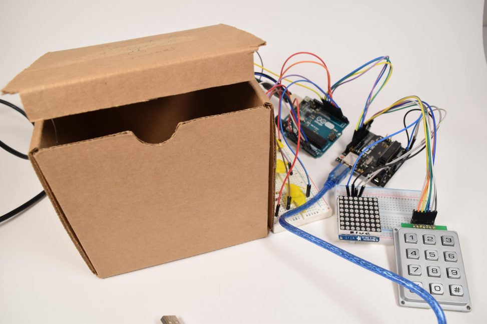
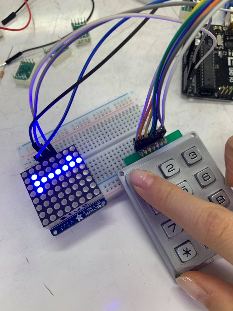
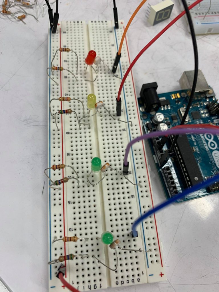
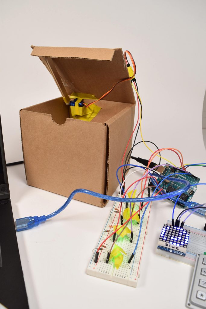
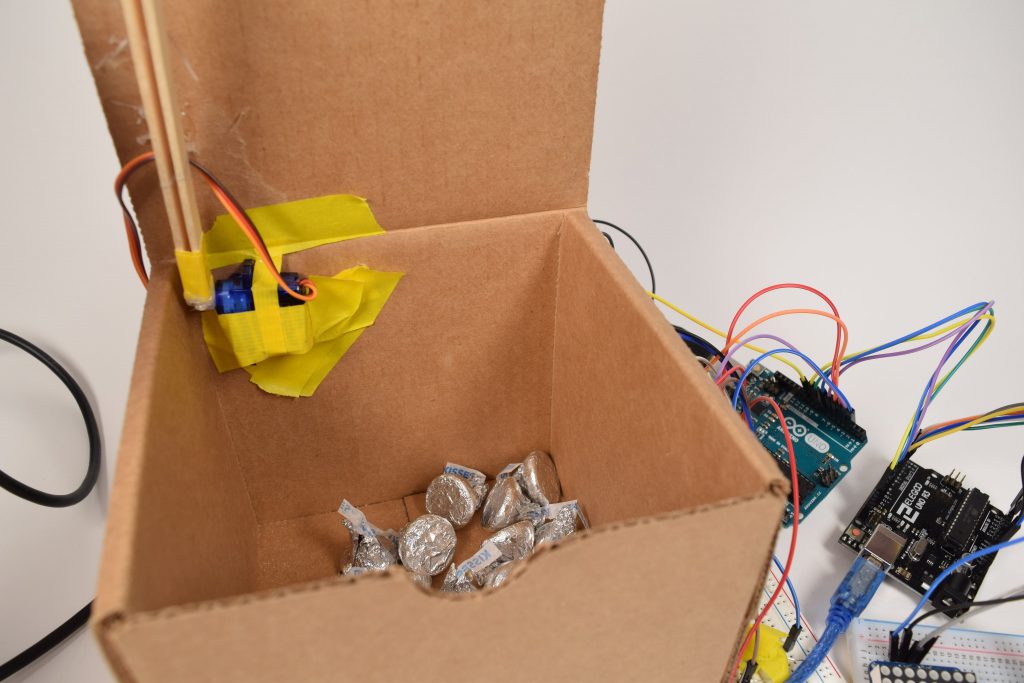
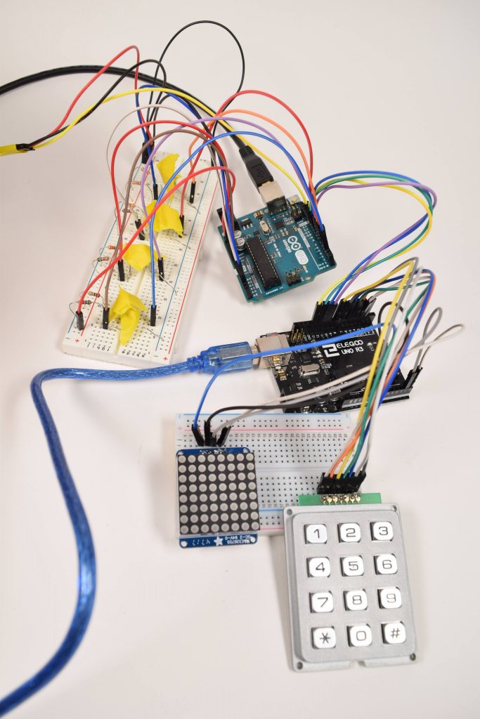
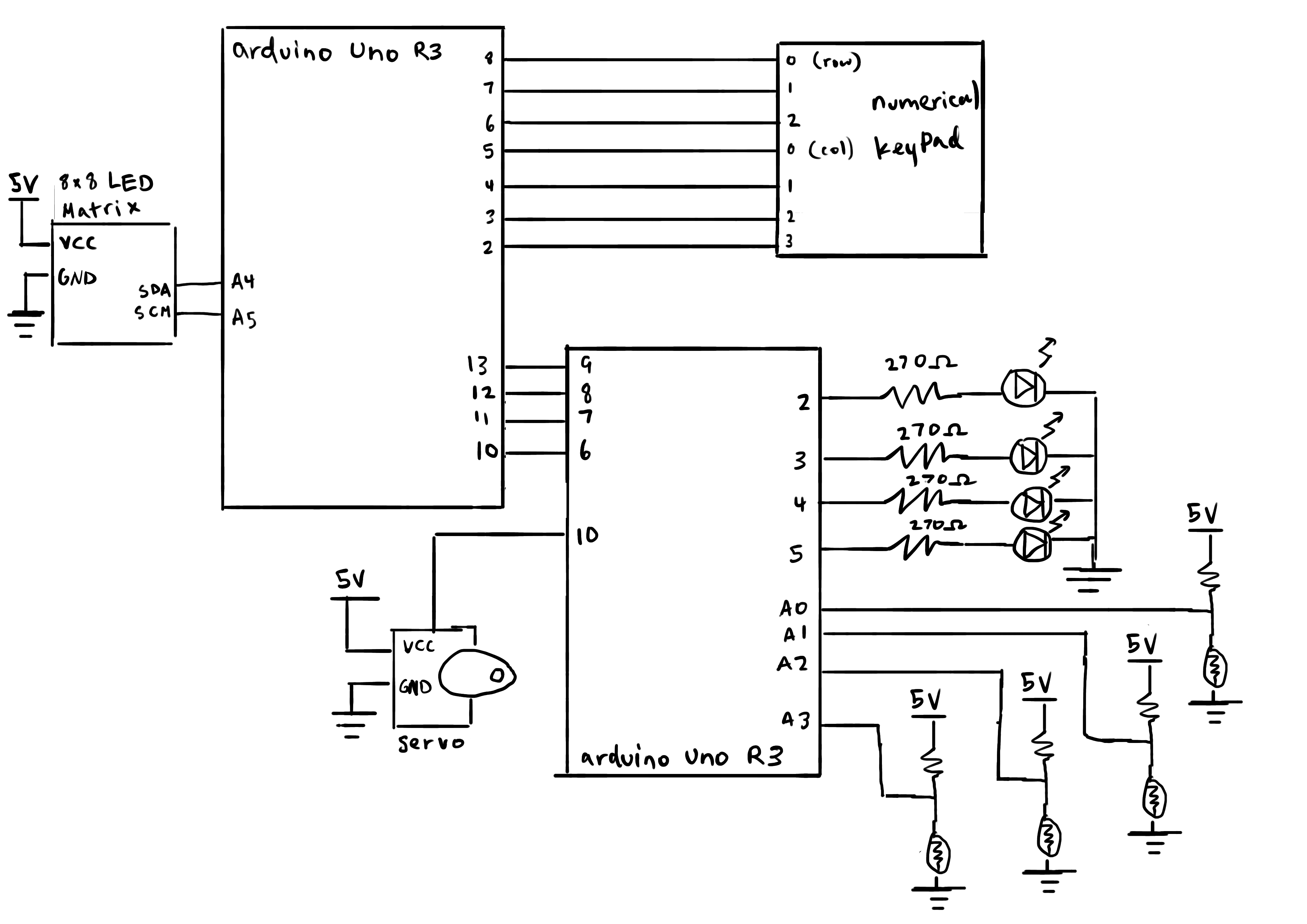
Comments are closed.