by Vicky Zhou and Stefan Orton-urbina
Description
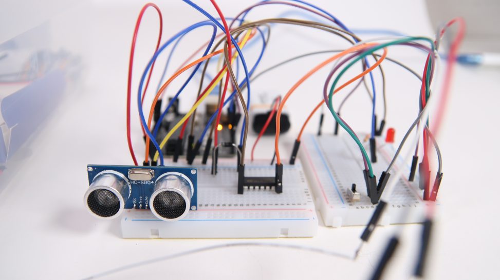
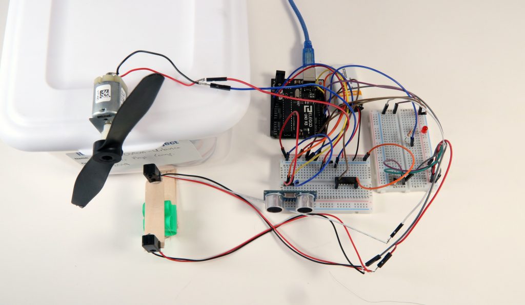
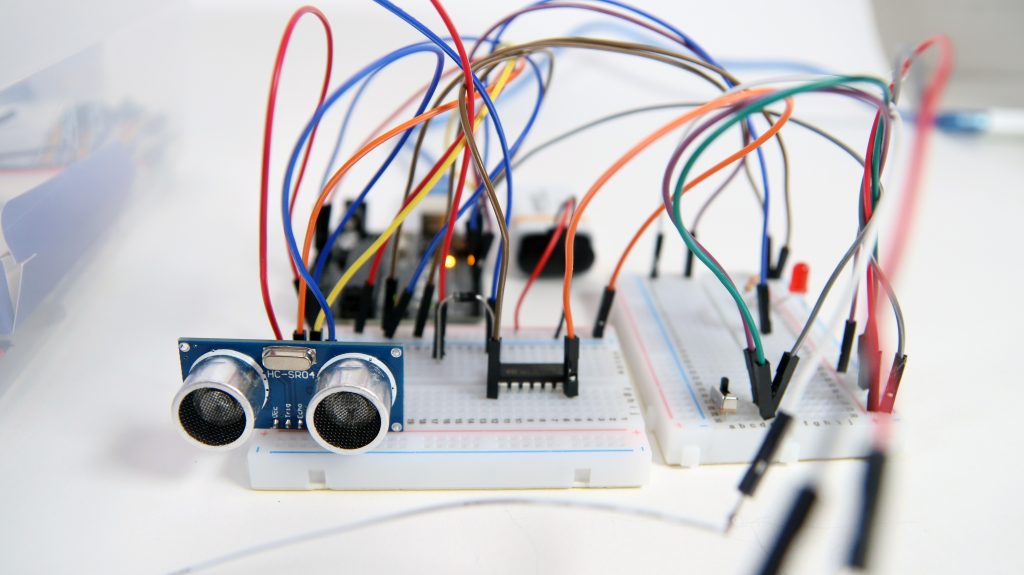
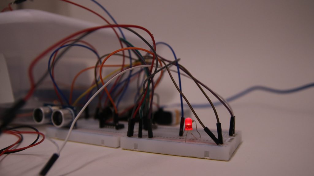
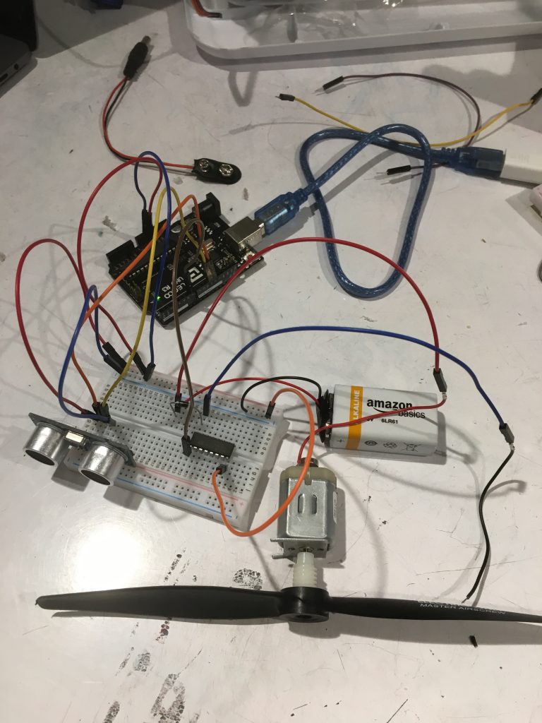
“Make an Entrance” is a double transducer that utilizes two forms of input (distance and rotational speed), and produces two forms of output (moving fan and an LED light). First, motion is detected through an ultrasonic sensor. The input of proximity of the sensor will then trigger a motor fan hitched on a rotary servo. This information will then be read by two IR Break Beam sensors — a sensor composed of one piece that sends a beam to another piece. When something comes in between these two pieces, the beam is broken, and the sensor picks up on that information. The amount of how fast a fan rotates is based on the amount of times the beam is broken within a certain amount of time. This information will then be fed as the input for an LED light, which will produce brighter or dimmer light.
Project

Process
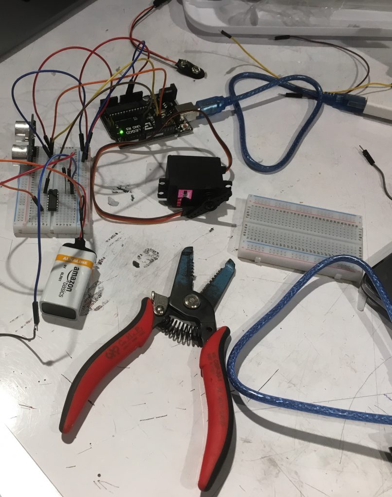

Connecting and testing IR Breakbeam sensors.
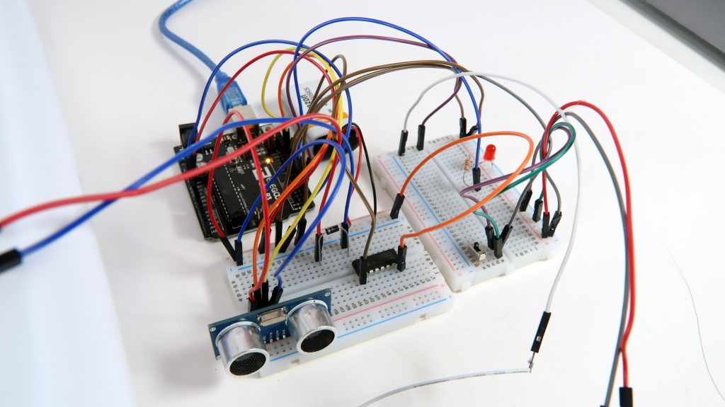
Schematic

Code
/*
 * Project 01: Double Transducer "Making an Entrance"
 * Stefan and Vicky
 * This code detects proximity, which then alters the speed of a fan,
 * which then alters the brightness of a LED light.
 */
// ---------------------------------------------------------------------------
// Example NewPing library sketch that does a ping about 20 times per second.
// ---------------------------------------------------------------------------

#include <NewPing.h>
#include <timer.h>

#define TRIGGER_PIN  12  // Arduino pin tied to trigger pin on the ultrasonic sensor.
#define ECHO_PIN     11  // Arduino pin tied to echo pin on the ultrasonic sensor.
#define MAX_DISTANCE 200 // Maximum distance we want to ping for (in centimeters). Maximum sensor distance is rated at 400-500cm.
#define IR_SENSOR 2 //IR sensor feedback for interrupt
#define MOTOR 6
#define LED 3
#define MOTOR_SWITCH 8


NewPing sonar(TRIGGER_PIN, ECHO_PIN, MAX_DISTANCE); // NewPing setup of pins and maximum distance.
volatile int fanPasses;
volatile int lightBrightness;
unsigned long timer = 0;
  const int waitTime = 150;
void computeAvg(){
  lightBrightness = fanPasses;
  fanPasses = 0;
}
void setup() {
  fanPasses = 0;
  pinMode(MOTOR_SWITCH, INPUT);
  pinMode(IR_SENSOR, INPUT_PULLUP);
  pinMode(MOTOR, OUTPUT);
  Serial.begin(115200); // Open serial monitor at 115200 baud to see ping results.
  attachInterrupt(digitalPinToInterrupt(IR_SENSOR), countFan, RISING);

}

void loop() {

  if ((millis() - timer) >= waitTime){
    computeAvg();
    timer = millis();
  }
  if (digitalRead(MOTOR_SWITCH) == HIGH){
    analogWrite(MOTOR, map(sonar.ping_cm(),0,35,200,32));
  }
  else{
    analogWrite(MOTOR, 0);
  }

  int ledOut =  map(lightBrightness,0,30,0,240);

  analogWrite(LED, ledOut);
  Serial.print(lightBrightness); // Send ping, get distance in cm and print result (0 = outside set distance range)
  Serial.println("cm");
  Serial.print(fanPasses); // Send ping, get distance in cm and print result (0 = outside set distance range)


}

void countFan(){
  fanPasses ++;
}
Discussion
The easiest part of “Make an Entrance” was setting up and utilizing the ultrasonic sensor and LED lights. The ultrasonic sensor and LED lights were the most straightforward of all the setups, and did not require much data manipulation aside from mapping out the different thresholds each required, to which we figured out through trials. The hardest parts of this project was figuring out a function that would transform the output data of an IR breakbeam (measuring the amount of times a fan passed) into output data that dictates how fast a fan is spinning (measuring amount of times a fan has passed, but with the variable element of time). At first, we used several different outside libraries to help incorporate this time variable (such as using a library that used a function that would read the current time now()), but that arose some issues, one of them being that at certain times, our code would stop receiving and sending messages to the latter half of the transducer (LED portion), and would only read and send information to the former half (spinning fan). Ultimately, we decided on scrapping the outside library that helped regular time, and instead relied on the internal Arduino time system, using code bits from Zach’s page.
Whereas previous homeworks and current exposure in the class focused on feeding inputs directly from the real world into the Arduino and receiving direct output, this project allowed us to learn how to create a system of inputs and outputs that feed into one another utilizing the “smart-ness” of an Arduino, allowing much of the “magic” to happen internally. Also, this project allowed us to learn how to convert raw data into one more comprehensible and usable by an Arduino through mapping (so as to the thresholds allow for fans to spin, and lights to go off). Furthermore, the biggest distinction in our project from others, was our ability to figure out how to convert the type of data we need from one form to another.
Had we decided to utilize a different a rotary servo that simply took in information digitally instead of analog (in other words, not on a spectrum and instead reading output from the ultrasonic sensor as “near” or “far”), we would have had an entirely different situation with dealing with the output of that rotary servo as it would then display information as being “left”, or “right”, rather than on a spectrum of slow to fast movement.
Comments are closed.