
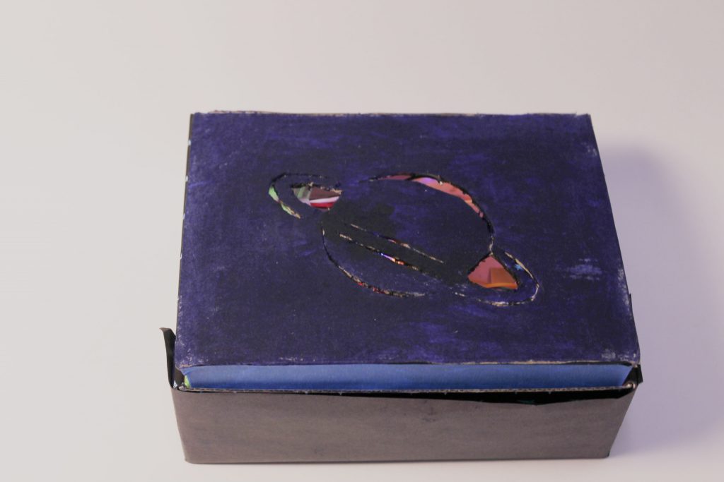
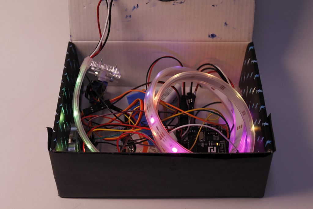
Narrative: Appearing as a simple, unwired blue box with a planet carved into the top, The Space Box is designed to be placed upon a desk to create a visual representation of how appropriate the space between the user and the person sitting next to them is. When the ultrasonic sensor on the side of the box detects that an object is close by, it triggers the rotation of a motor inside of the box, which causes the color gradient going through an LED strip visible through the planet carving on the lid of the box to change much quicker, drawing the neighboring person’s eye and reminding them to move out of the user’s personal space.
Progress and Discussion:


From the moment this project was announced, we knew we wanted a chance to use the individually addressed LED strips to build something that could create a visual representation of another domain through a gradient along an LED strip. Initially we envisioned something that would use sound, through either pitch or volume, to change the rate at which colors would cycle through the strip, to create a physical version of an old Window’s Music Player type visual representation of a song, but when we realized that sound would be too difficult to use, we began brainstorming other attributes that could vary along a gradient, and came up with distance. By creating a visual representation of distance, we figured we could create a device that would be helpful in settings where personal space is not always respected, such as classrooms, by providing a gentle reminder to neighboring students when they are too close.
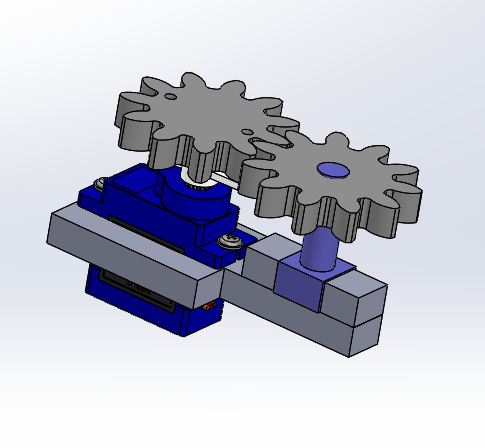
As the goal of the project was to create a double transducer, we sought next to think of an intermediate step that could be both produced and read by the Arduino. As we had used both servo motors and potentiometers in class, we were drawn to the idea of using motion, but knew we would then have to build a mechanical component for the motor to be able to rotate the potentiometer. Using CAD, we modeled gears that would fit around the dial of one of the potentiometers found in the Physical Computing room and could be attached to the propeller on the servo motor using screws. When assembled, the servo-motor and potentiometer system worked perfectly, but had a fairly long delay time due to the time needed for the motor to get to its final position. However, we decided that this worked well with our vision for the final device, as it was created to alert individuals that were spending extended periods of time invading the space of others, not to immediately respond to every shift in nearby movement. However, as we were directly mapping the distance recorded by the ultrasonic sensor to the motor position, any movement next to the box resulted in an audible twitch in the motor, which we thought would be distracting in a classroom setting, so we changed the code so that the motor would only shift at certain threshold levels of distance.
In order to create a functional prototype of The Space Box as an actual product, we wanted to keep all of the parts within one box, powered by internal batteries, and create an idea of the final aesthetics of it as an object that is meant to represent a measurement of distance through light in a way that is not only helpful, but beautiful. The time we had for this project limited us to using a cardboard box, but in its ideal form, The Space Box would be built out of a sturdier, more beautiful opaque material, that would have a hole for the ultrasonic sensor, and an engraving on the top representing a pun on the nature of the box as a detector of personal space through using a symbol of outer space through which the lighting gradient would ultimately be visible.
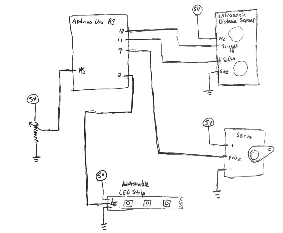
Schematic:
Code:
//The Space Box
//Summary: Identifies whether certain threshholds of distance from an ultrasonic censor have been met, and changes the location of a servo motor in accordance to these thresholds, while mathematically dividing the color wheel into a gradient which is assigned to the LEDs on an LED strip with a cycle time determined by the position of the servo motor, as determined by the location of a potentiometer.
//inclusions required by libraries
#include <Adafruit_NeoPixel.h>
#ifdef __AVR__
  #include <avr/power.h>
#endif

#include "Arduino.h"
#include "SPI.h"
#include <NewPing.h>
#include <Servo.h>

#define LEDPIN 2
#define TRIGGER_PIN  12  // sets trigger pin of unltrasonic sensor
#define ECHO_PIN     11  // sets echo pin of unltrasonic sensor
#define MAX_DISTANCE 200 // Maximum distance used for ultrasonic sensor

Adafruit_NeoPixel strip = Adafruit_NeoPixel(30, LEDPIN, NEO_GRB + NEO_KHZ800);  //setup of LED strip
NewPing sonar(TRIGGER_PIN, ECHO_PIN, MAX_DISTANCE); // NewPing setup of pins and maximum distance.

Servo myservo;  // create servo object

int val;    // variable to read the value from the analog pin
int nLEDs = 30;   //value for number of LEDs used
int POTPIN = A5;    //initialites pin for potentiometer
int potVal = 0;     // initializes variable for potenetiometer value
int waitTime;       //initializes delay time between sensor readings
int distance = 0;   //initializes variable for ultrasonic distance

void setup() {
  pinMode(POTPIN, INPUT);
  strip.begin();
  strip.setBrightness(50);
  strip.show();
  myservo.attach(9);    //attaces servo
  Serial.begin(9600);
}

void loop() {
  Serial.println("main Loop");
  distance = sonar.ping_cm();
  val = map(distance, 0, 50, 0, 180);     // scale it to use it with the servo (value between 0 and 180)
  myservo.write(val);   //write value to servo
  delay(15);    //ensures servo is finished moving before reading potentiometer
  strip.show();   // write all the pixels out
  potVal = analogRead(POTPIN);
  waitTime = potVal/100;
  Serial.println(val);

  int wait = 30;
  uint16_t i, j;
  //loop to write LEDs based on color from wheel
  for(j=0; j<256; j++) {
    for(i=0; i<strip.numPixels(); i++) {
      strip.setPixelColor(i, Wheel((i+j) & 255));
    }
    strip.show();
    delay(wait);
    Serial.println(wait);
  }
}

//code to cycle through different LED colors, inspired by the math in the code in the examples in the Arduino library LPD8806
uint32_t Wheel(byte WheelPos) {
  WheelPos = 255 - WheelPos;
  if(WheelPos < 85) {
    return strip.Color(255 - WheelPos * 3, 0, WheelPos * 3);
  }
  if(WheelPos < 170) {
    WheelPos -= 85;
    return strip.Color(0, WheelPos * 3, 255 - WheelPos * 3);
  }
  WheelPos -= 170;
  return strip.Color(WheelPos * 3, 255 - WheelPos * 3, 0);
}
Comments are closed.