Overview:
A lamp used to indicate the moisture present in the air through color in order to prevent frequent nosebleeds and indicate that I should turn my humidifier on.
With a motion sensor, the lamp intended for my bedroom has two states in order to conserve electricity and provide suitable lighting for sleep and getting ready in the morning. Humidity level changes the color of the LED strips; an a rocker switch was also added to turn off the lamp completely when I am away from my apartment.
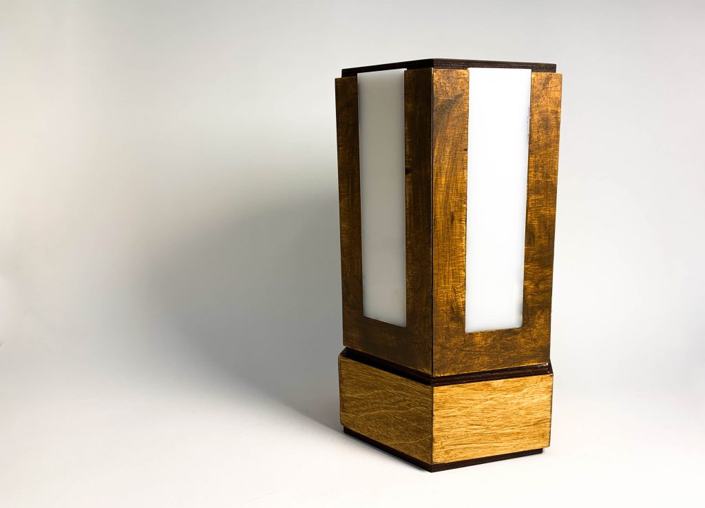
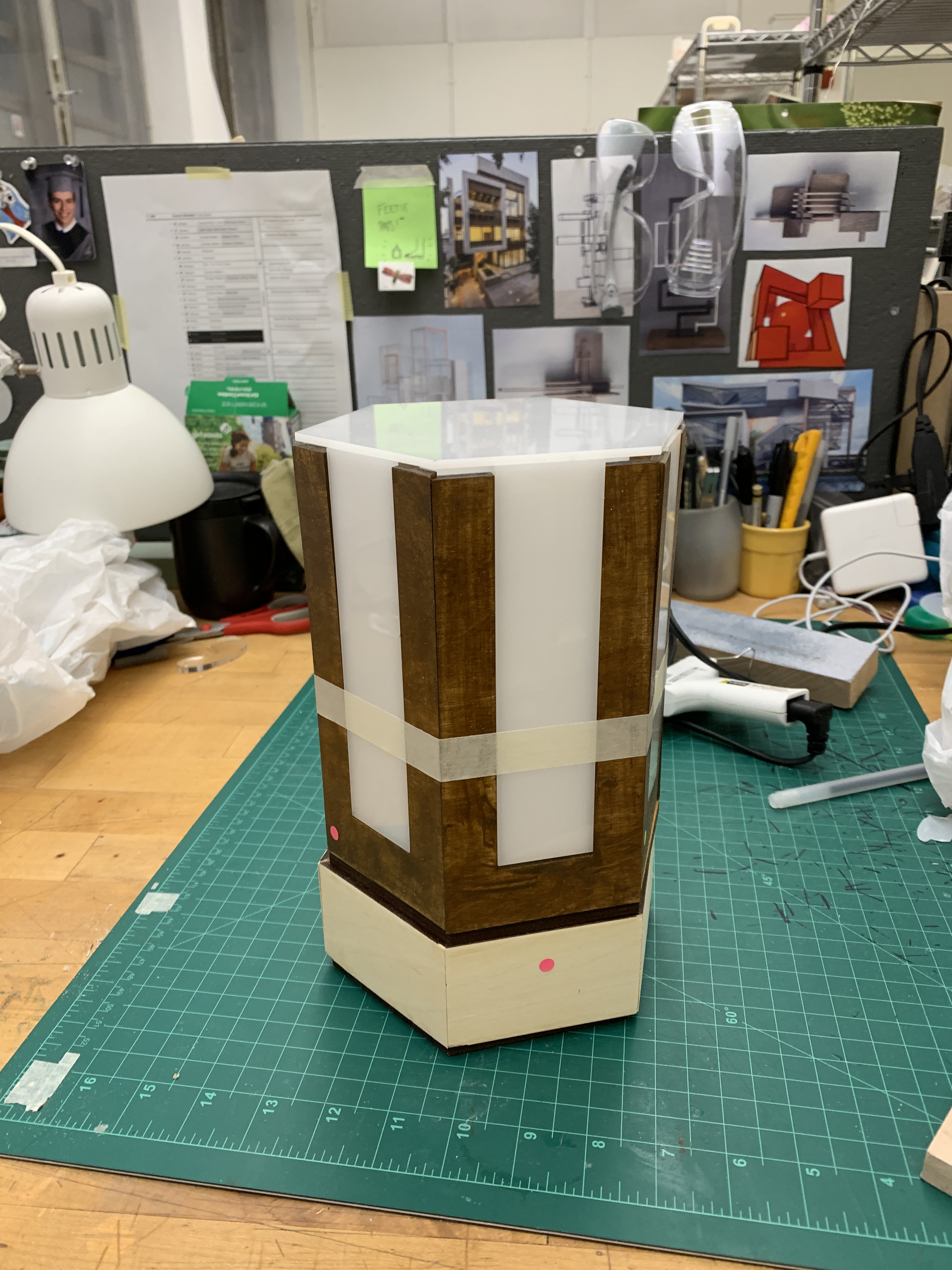
Overview Image
Detail Images:
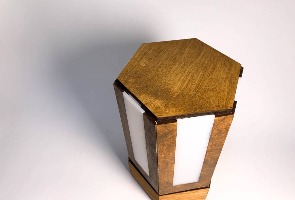
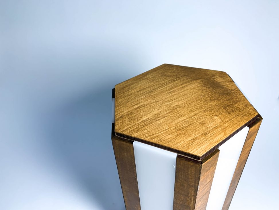
Close up of hexagonal shape and acrylic panels
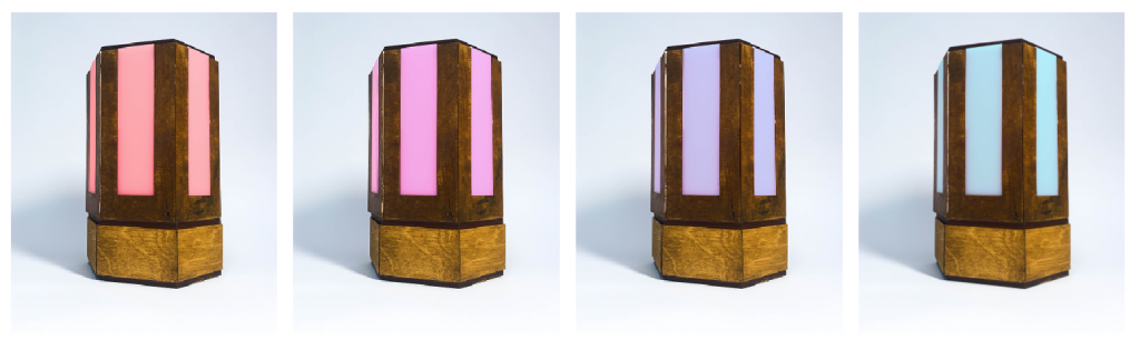
Light color depends on humidity level of the environment. Light changes in increments on the RGB scale. 1. Red Hue: 0-30% humidity level, 2. Pink Hue: 30-60% humidity level, 3. Purple Hue: 60-90% humidity level, 4. Blue Hue 90-100% humidity level
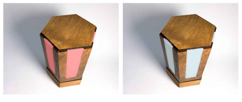
Two States of Lamp dependent on whether motion is sensed: Active displays humidity reading (left image) and idle (right image)
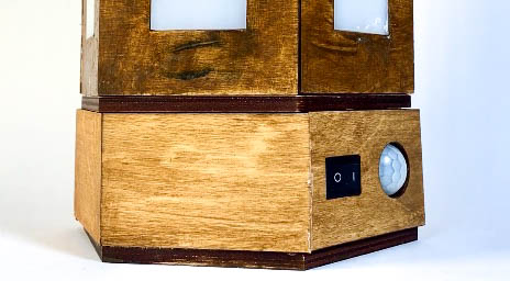
Rocker Switch and PIR motion sensor exposed on lower section of lamp
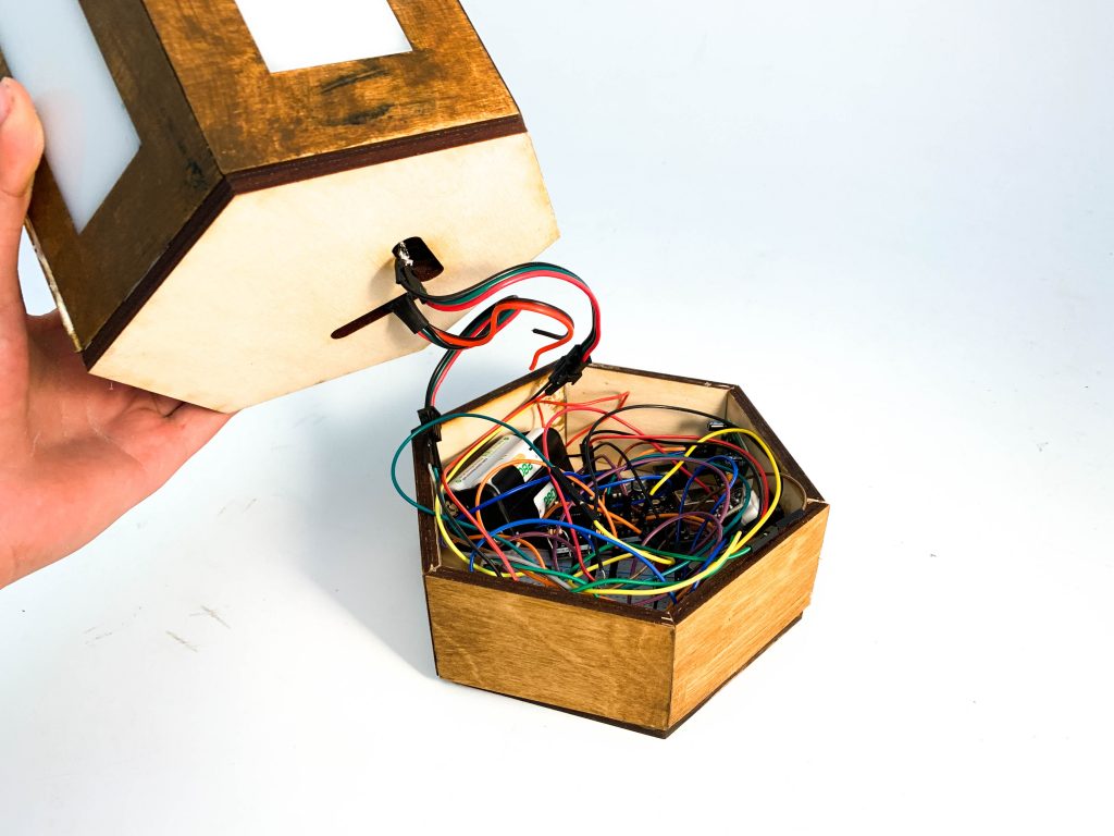
Two sections of lamp: Upper housing holds the LED strips and lower housing holds the battery, breadboard, and Arduino
ON/OFF rocker switch demonstration and motion sensor adjacent to switch
Motion detection when lamp is on either triggers the active state: displaying the humidity reading or if motion is not detected the idle state: a pale white color.
Opening demonstration of inner lamp components
Process:
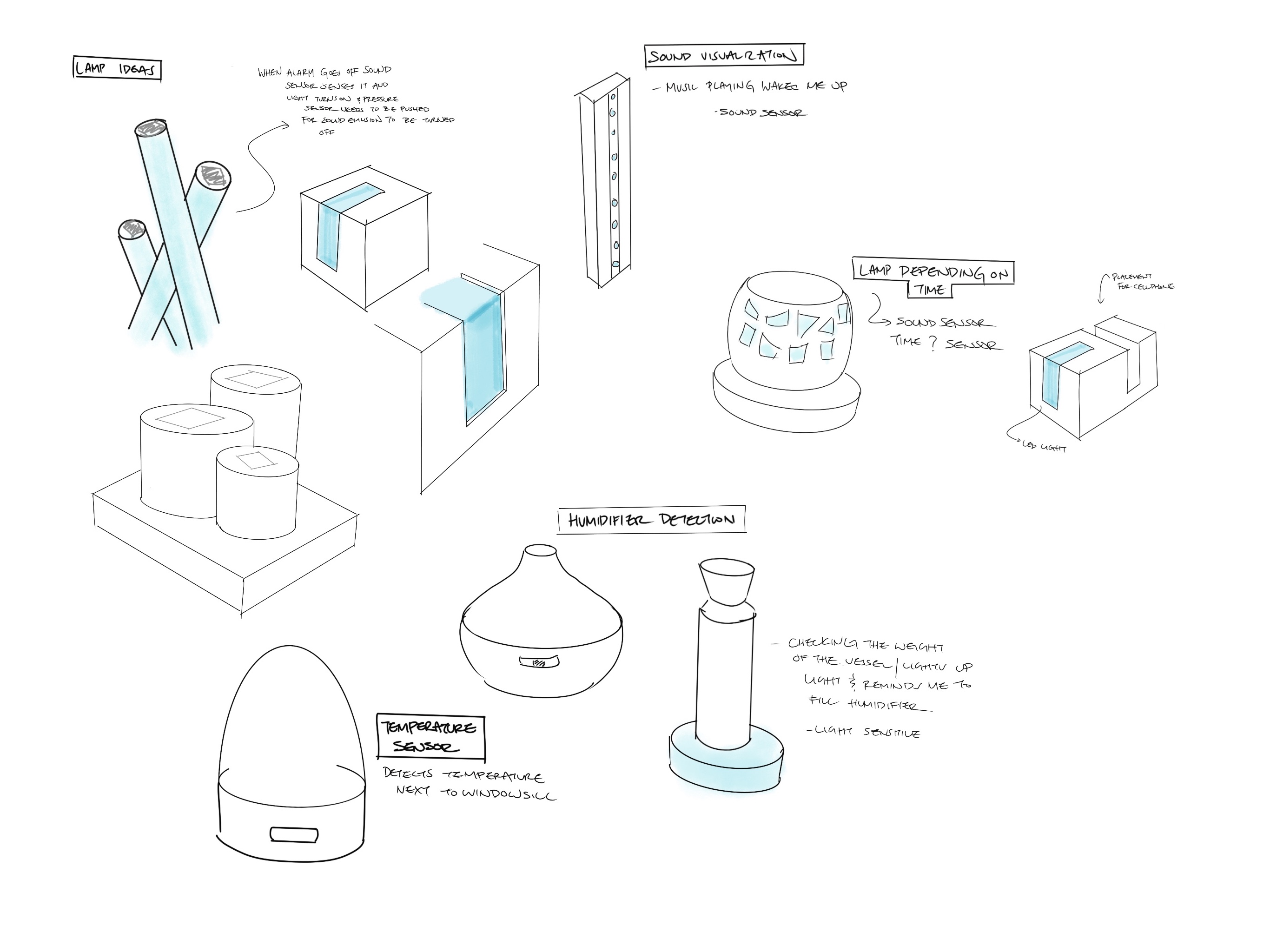
Initial Idea Sketches
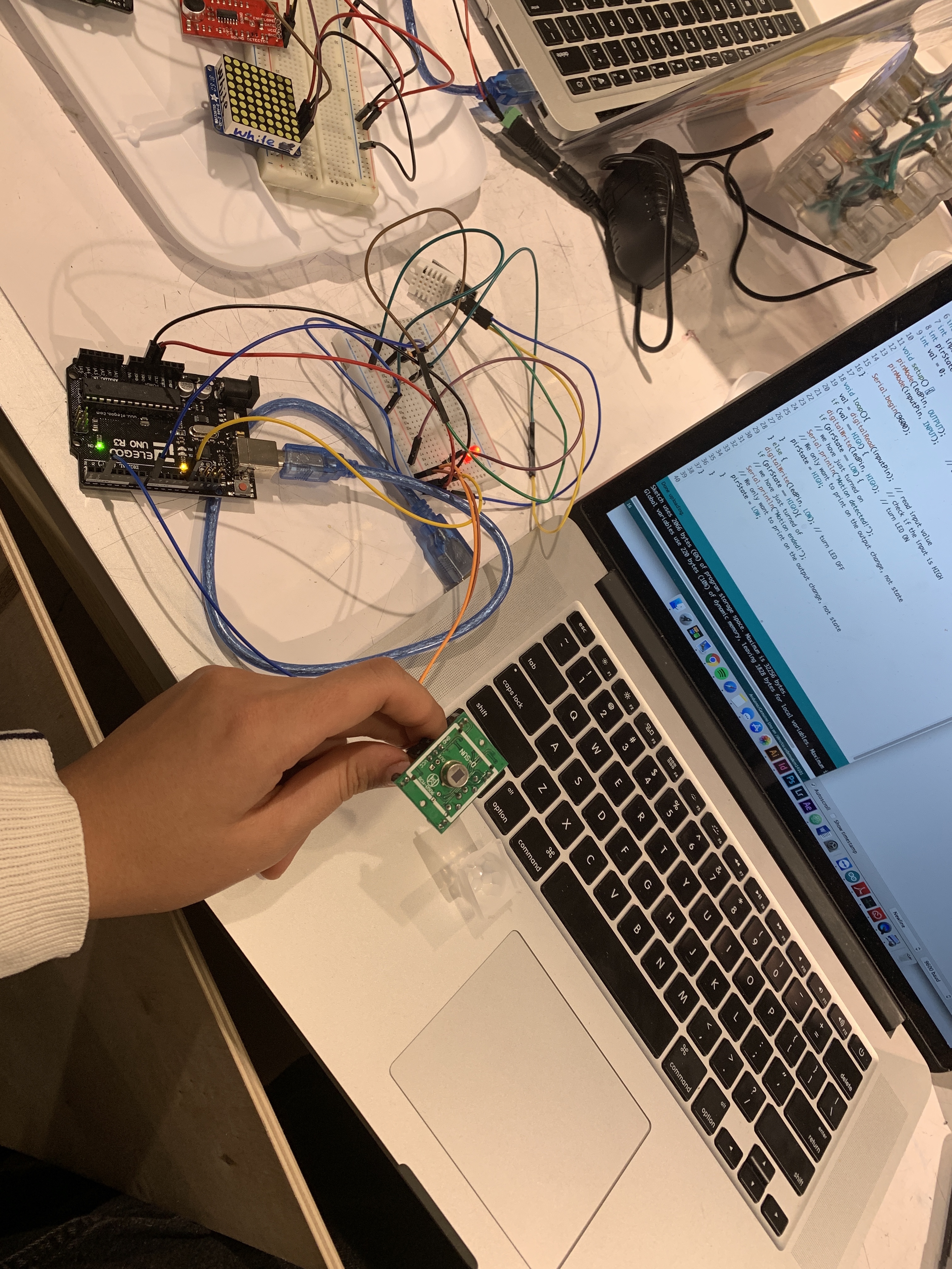
PIR motion sensor affecting an LED
I started the project with experimenting with the DHT sensor as well as the PIR sensor. Once I developed a basic understanding of the two sensors, I began to move on to fabrication of the physical piece.
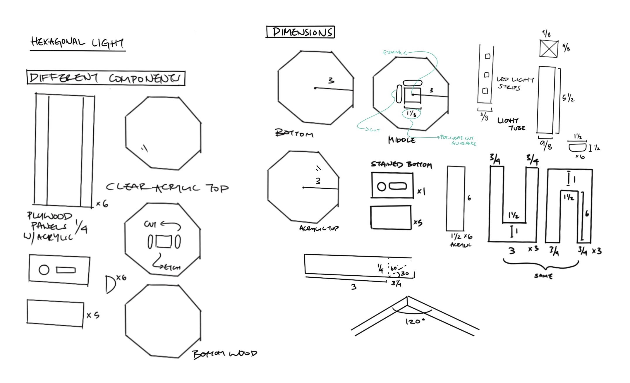
Sketches exploring the construction and laser cut pieces of the lamp.
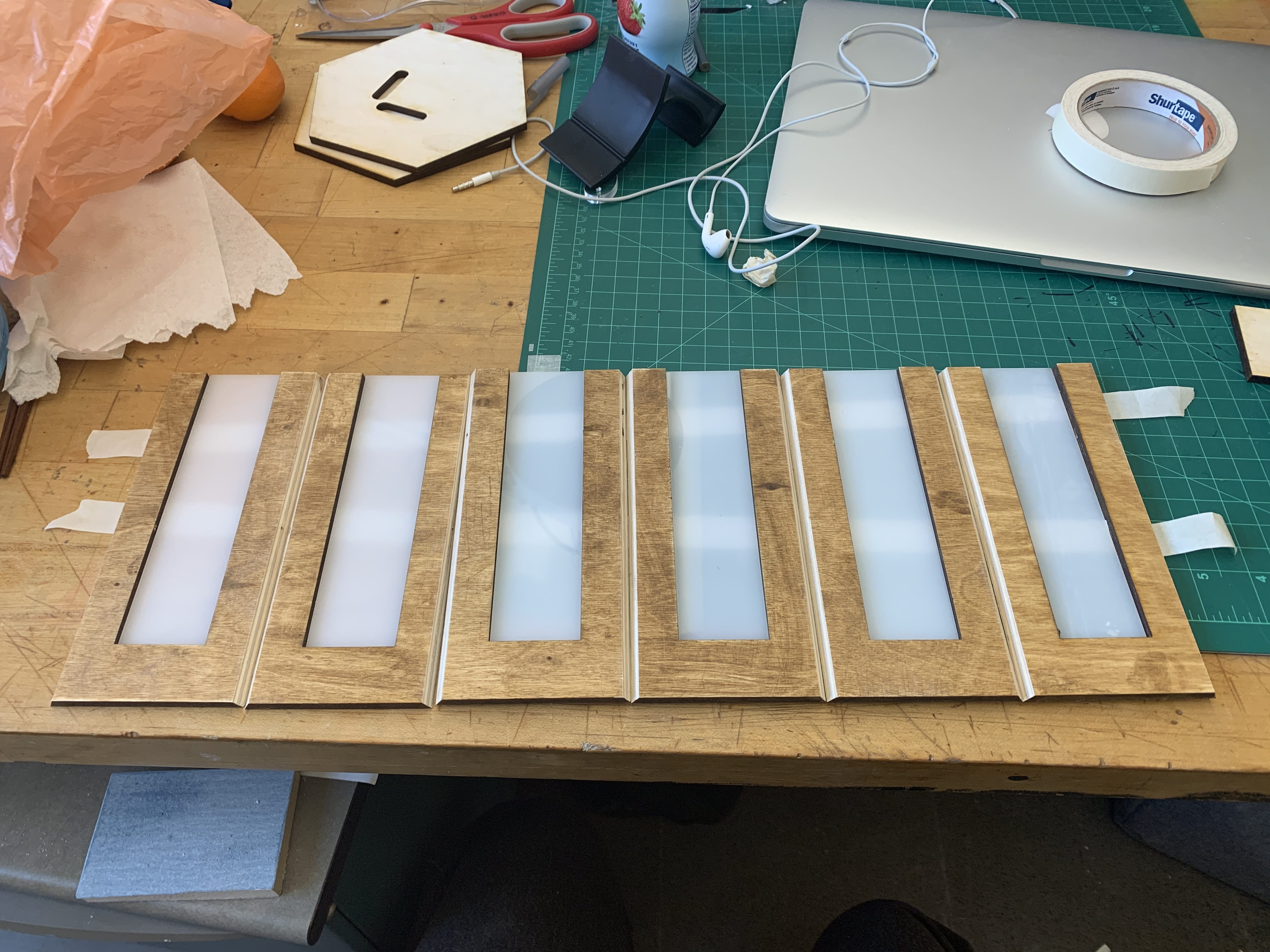
After sawing the angles on the laser cut pieces, I laid the half stained pieces down in order to test my cuts.
Fully stained wood pieces and bottom piece attached with tape. Experimenting with different materials for the top cap
At this point with most of my physical components completed, I decided to move onto the code. I had some difficulty with the map function and converting the humidity reading to an RGB scale with the LED strip. After asking for help, I moved on to the PIR sensor and rocker switch. I originally hadn’t intended to add the rocker switch; however, if I were to use this lamp I wouldn’t want to open the bottom section and unplug the battery every time I leave for an extended period of time.
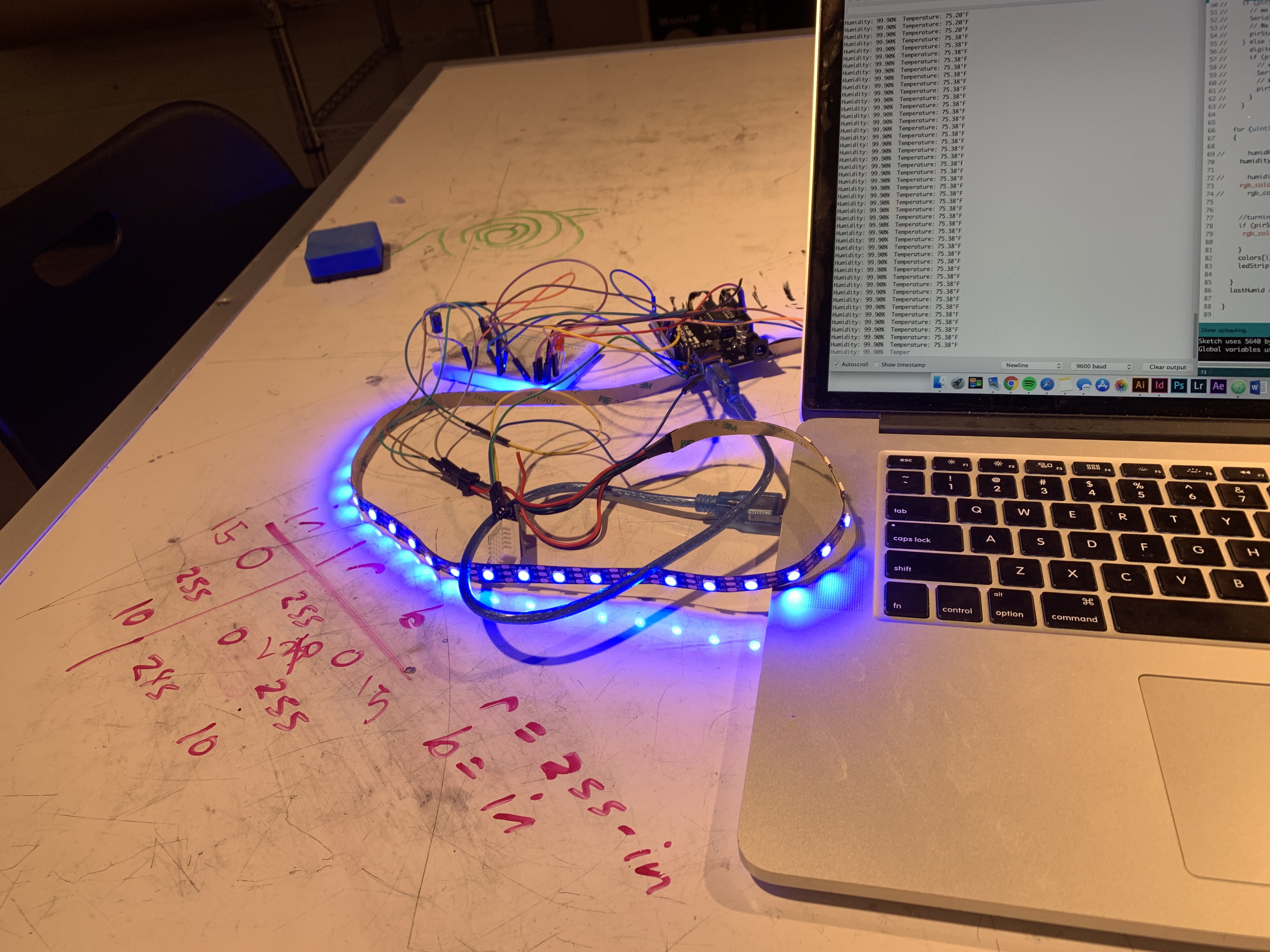
Had a lot of difficulty with the LED colors changing based on humidity reading. Asked Zach for help (pictured on whiteboard!)
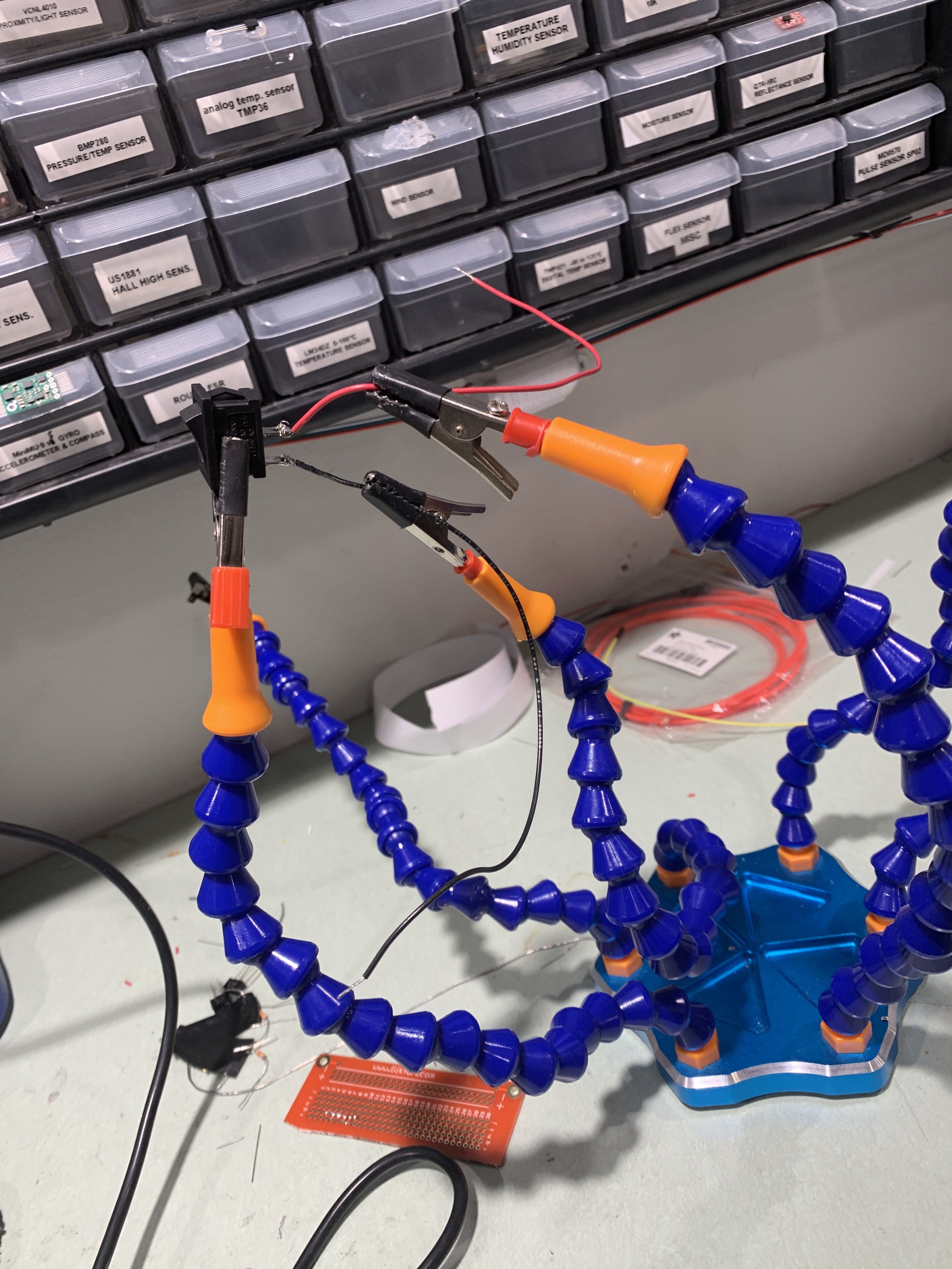
First time soldering experience with a rocker switch! Rocker switch turns lamp on and off to conserve energy
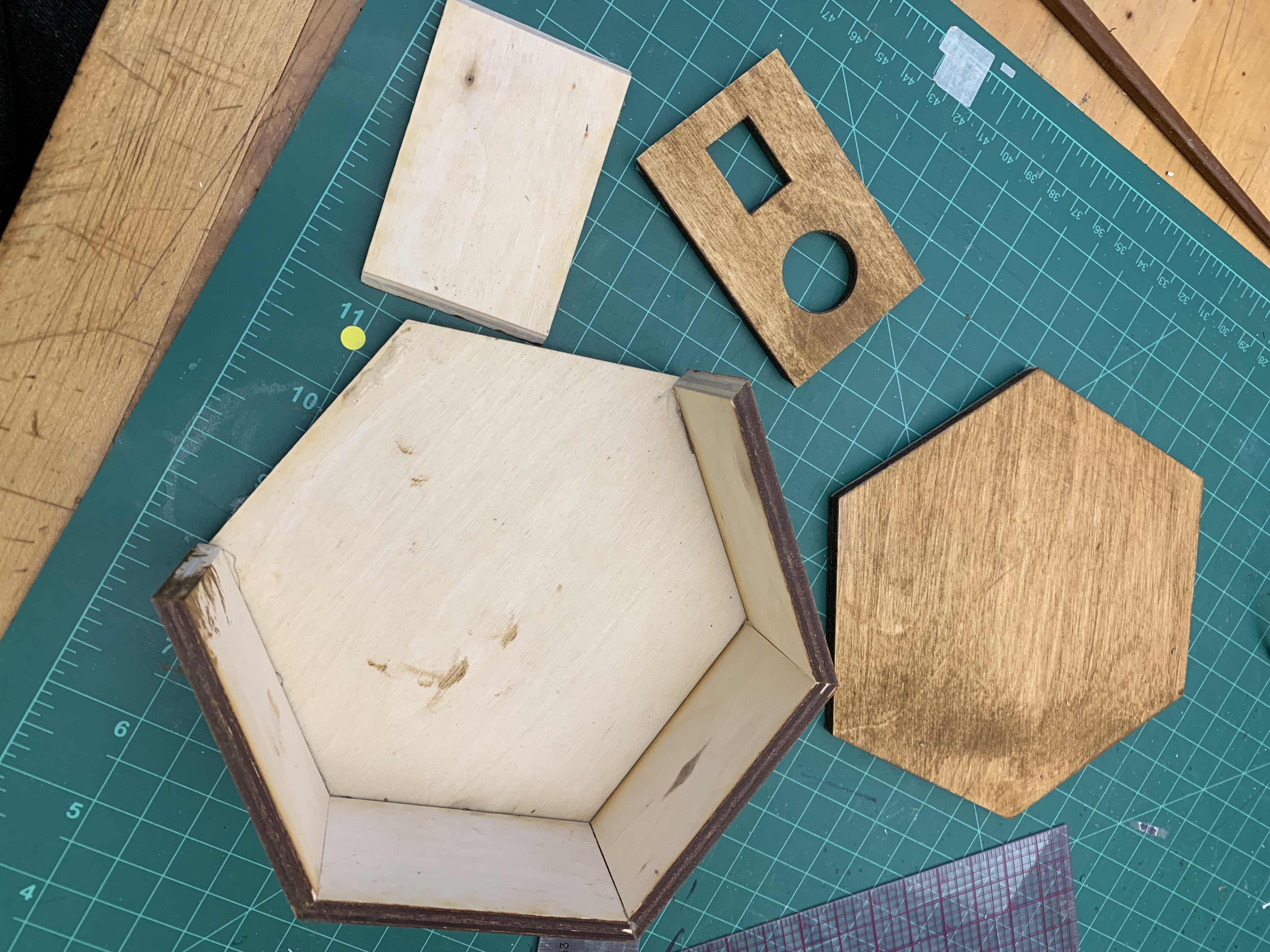
Figuring out dimensions of bottom pieces and decided to work with wood for the top cap
Discussion:
I was pretty satisfied with the overall result of the lamp, through this project I was able to grow more comfortable with coding and understanding how different inputs and outputs can influence each other. I was also thankful for the opportunity to create something that I can used in everyday life that serves a purpose. I do wish that I had the time to create another physical prototype due to bad craft in some angled cuts and over-staining the wood. On the electronics side of things, I wish I could have incorporated pulsing with the lights in order to represent abnormally low humidity readings. I believe that incorporating a LCD display screen could also give some specifications to the moisture content in the environment.
From this project I learned that balancing the creating of both electronics and physical models is very important. Though this time I balanced both pretty efficiently, I do wish I had spent more time with the electronics side of the project because that’s the field I feel more uncomfortable with. My advice to my future self would be to understand more about C and learn all the capabilities of the sensors before starting on the physical prototypes.
From the critique my peers stated that the physical form was “very aesthetically pleasing” and an “interesting concept” in that I designed my own housing. They recommended I used a break beam so that when I walk in and out of the room the lamp could make sure that I was in the room. I would like to explore the use of the break beam because that seems like something that doesn’t require constant motion and seems to be more of a ON/OFF state while motion is more analog. I am also interested in exploring if there is a way for the humidity levels to change the lights more gradually, whether that is trying a new library or changing something in my code. Overall, this was a fun project to do and I definitely learned more about coding and some fabrication methods.
Schematic:
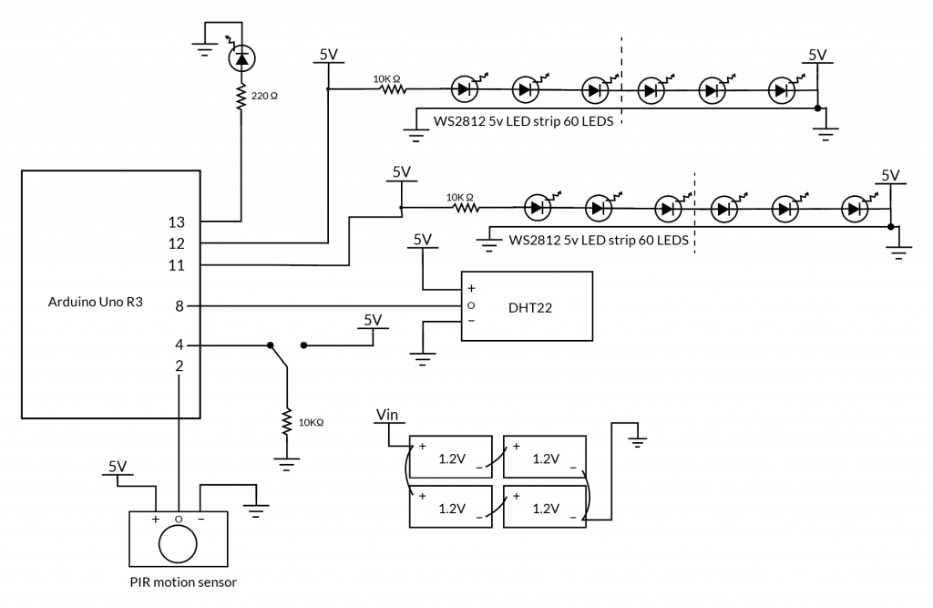
Wiring Diagram of Lamp
Code:
/*
  Project Two: An Assistive Device for someone you know well
  Elena Deng, edeng1

  Designed a lamp used to detect the humidity of the room meant for me to prevent my chronic nosebleeds in winter.

  Code can be used to program a lamp that takes in the humidity reading through a DHT sensor and depending on whether motion is sensed in the PIR sensor, one of two LED states is activated. There is also a rocker switch used to turn the lamp on/off

  Sensors and switches used: DHT22, RGB LED strip, PIR Motion Sensor, Rocker switch

  Used the Pololu LED strip library, DHT sensor library, and Adafruit's
https://learn.adafruit.com/pir-passive-infrared-proximity-motion-sensor/using-a-pir-w-arduino
*/

#include "DHT.h"
#define DHTTYPE DHT22
#include <PololuLedStrip.h>

const int DHTPIN = 8;
const int ledPin = 13;
const int inputPin = 2;
const int buttonPin = 5;
int buttonState = 0;
int pirState = LOW;
int val = 0;
int ledState;

DHT dht(DHTPIN, DHTTYPE);

//two ledStrips
PololuLedStrip<12> ledStrip;
PololuLedStrip<11> ledStrip2;
#define LED_COUNT 60
rgb_color colors[LED_COUNT];


int lastHumid = 0;       // compares the last temperature of the loop

void setup() {
  Serial.begin(9600);
  pinMode(ledPin, OUTPUT);      // declare LED as output
  pinMode(inputPin, INPUT);     // declare sensor as input
  pinMode(DHTPIN, INPUT);       //humidity sensor is an input
  pinMode(buttonPin, INPUT);    //switch pin is an input

  dht.begin();
}

void loop() {
  float h = dht.readHumidity();
  int humidReading = h;
  int humidity;

  //prints humidity level reading
  Serial.print(F("Humidity: "));
  Serial.println(h);


  val = digitalRead(inputPin);  // read input value of motion sensor
  digitalWrite(ledPin, val);  //if motion is sensed the led is HIGH and vice versa
  ledState = digitalRead(ledPin);  //reads whether the led on breadboard is on
  buttonState = digitalRead(buttonPin);  //reads the state of the switch

  for (uint16_t i = 0; i < LED_COUNT; i++)
  {
    humidity = map(humidReading, 0, 100, 0, 255);  //change 0-100 scale of DHT sensor to 0-255 RGB scale

    rgb_color red = rgb_color(280 - humidity, 40, humidity); //range of colors of LED
    rgb_color black = rgb_color(20, 20, 17);  //idle state of LEDs

    //turn on active state if motion is sensed and switch is on
    if (buttonState == HIGH) {
      if (ledState == HIGH) {
        colors[i] = red;
      }
    }
    //turn off if motion is not sensed and switch is off
    else if (buttonState == LOW) {
      if (ledState == LOW) {
        colors[i] = black;
      }
    }
    ledStrip.write(colors, LED_COUNT);
    ledStrip2.write(colors, LED_COUNT);
  }
  lastHumid = humidity;   //compare the humidity reading to last loop
}
Comments are closed.