A companion device designed to complement and augment the functionality of a humidifier.
Ian Shei
Winters in Pittsburgh are long and cold, and with the brisk weather comes excessive heating of buildings. Heating through steam radiators invariably drives indoor relative humidity uncomfortably low, causing dry skin, nosebleeds, respiratory problems, and aggravated allergies and skin conditions. It can also dry nasal passages, leading to greater susceptibility in contracting cold viruses. Experts recommend keeping indoor relative humidity between 40 and 60% for comfort, reduction of airborne bacterial and viral transmission, and minimization of mite and fungal populations.
However, most humidifiers, including mine, don’t sense relative humidity and thus rely on manual activation in order to operate. This introduces much guesswork to the process – unless one has a humidity sensor handy, they most likely turn on the humidifier when it “feels” dry (humidity readings in weather forecasts don’t accurately reflect indoor conditions).
This often results in forgetting to turn on the humidifier if one is preoccupied or busy. Personally, the main reason I have a humidifier is because of sensitive skin, but I find that I could be using the humidifier when the cause for irritated skin at the moment is unrelated (stress, sleep deprivation, air pollution, etc.).
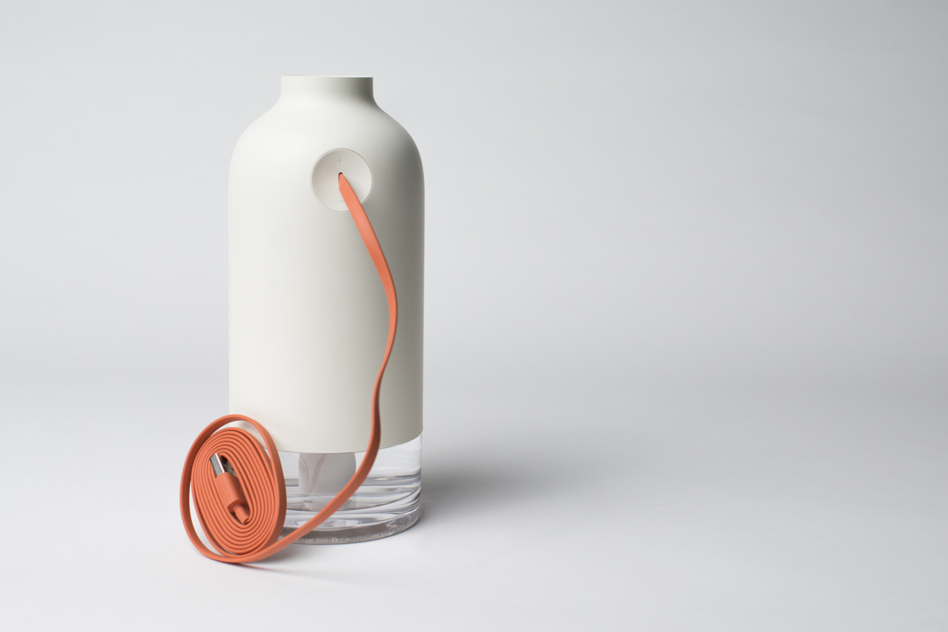
My humidifier. It sits on my desk in my room and is essential to surviving a Pittsburgh winter.
My objective with this project was to create a base for my humidifier that would noticeably signal when the relative humidity in a room had fallen below a set threshold, thus signaling that the humidifier should be turned on. Since monitoring of humidity is constant and automatic, the base could attract a person’s attention using lighting so that they don’t neglect increasing the humidity. By activating based on an environmental measurement, any guesswork in the indoor humidity is eliminated – the humidifier would only be turned on when necessary as dictated by the sensor’s reading.
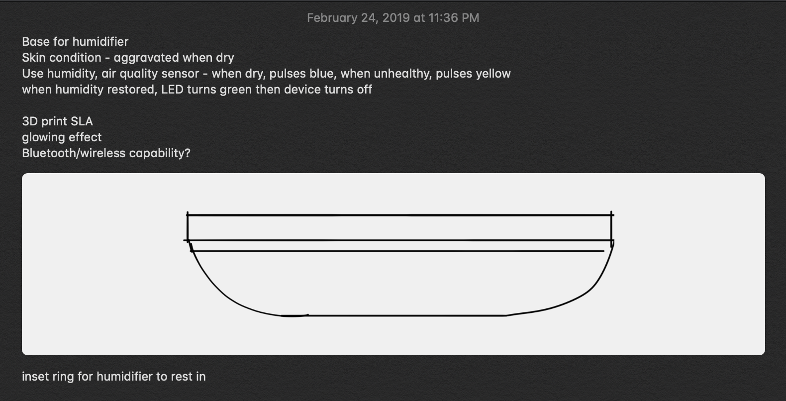
Some notes and a quick phone sketch early in the process.
I began by wiring and testing this project’s essential component: an inexpensive DHT22 temperature and humidity sensor. To verify that the part functioned as described, I used an Arduino Uno to act as an intermediate between the DHT22 and the serial monitor on my computer.
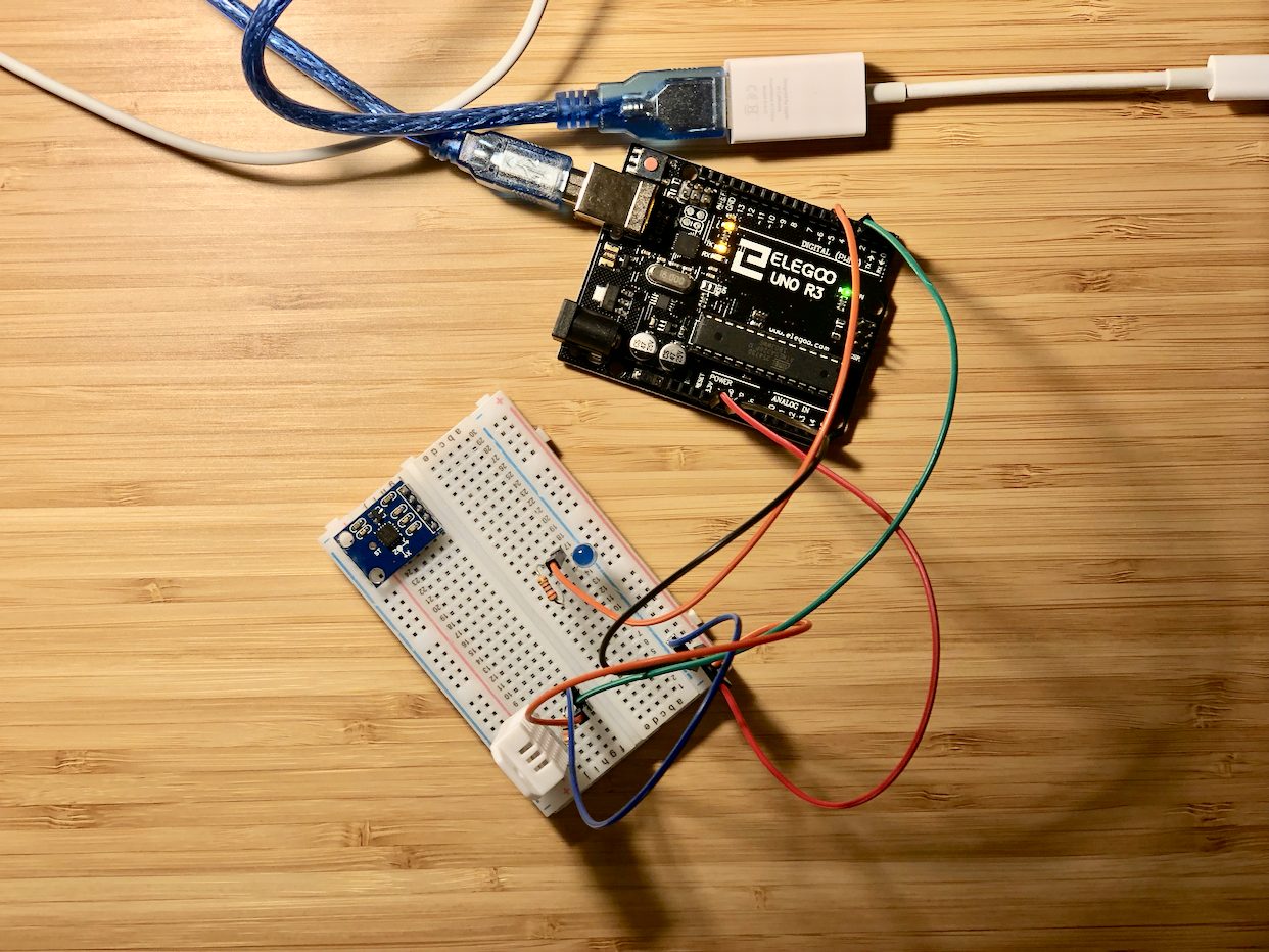
The DHT22 sensor (the white block in the lower left corner of the breadboard) connected to an Uno.
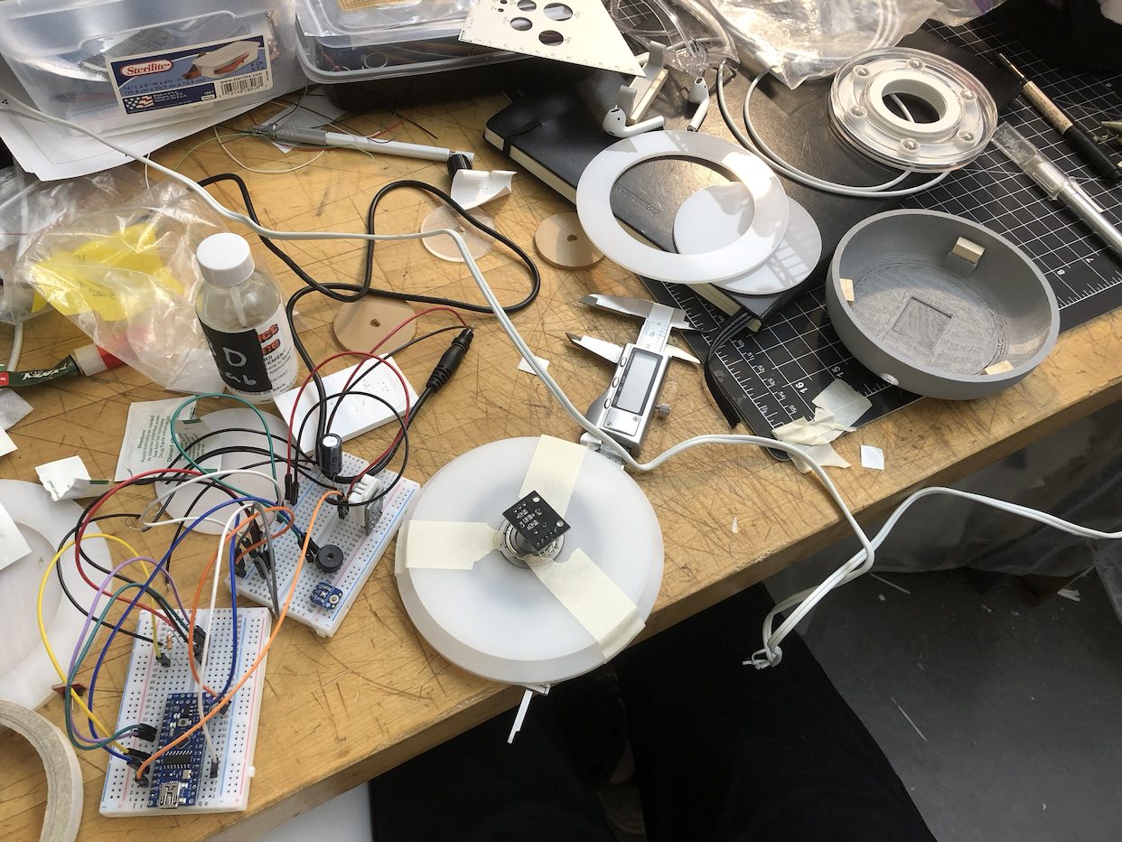
With the humidity sensor verified to be working, I connected a rotary encoder, ambient light sensor, and a ring of 24 RGBW LEDs called a NeoPixel Ring. The NeoPixel’s purpose is to display the relative humidity through pulsing (the faster the pulsing, the drier the air) in order to alert the owner to turn on a humidifier. It also works with the rotary encoder to adjust the humidity level below which the LEDs will turn on, serving as a display to set the threshold. Finally, the ambient light sensor controls the brightness of the LEDs so as to not be blinding in a dark room.
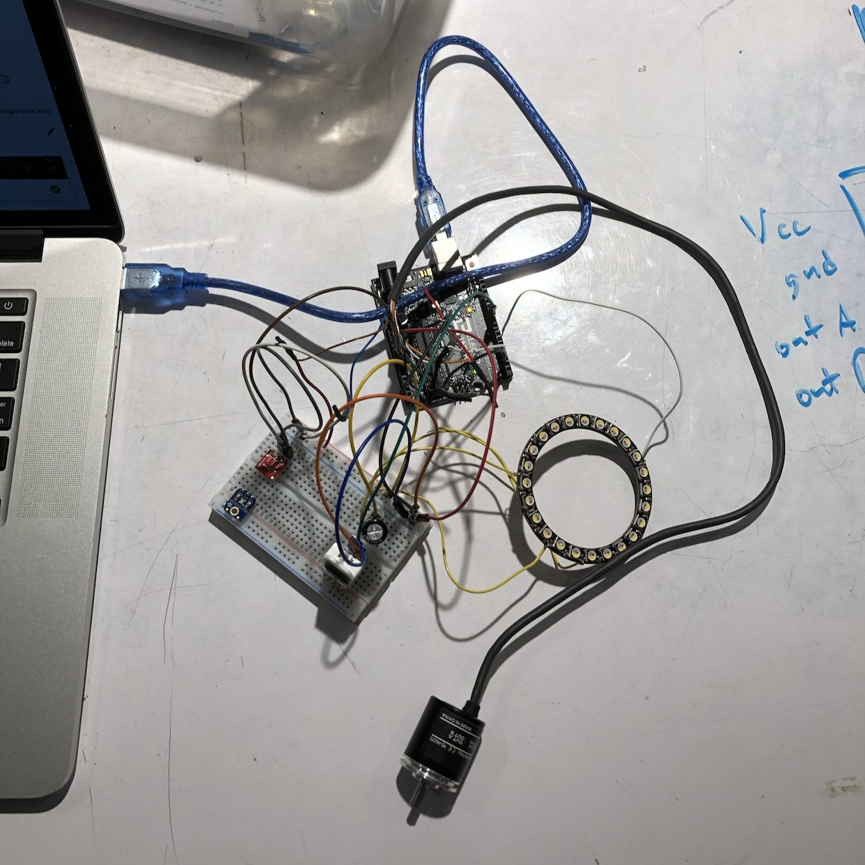
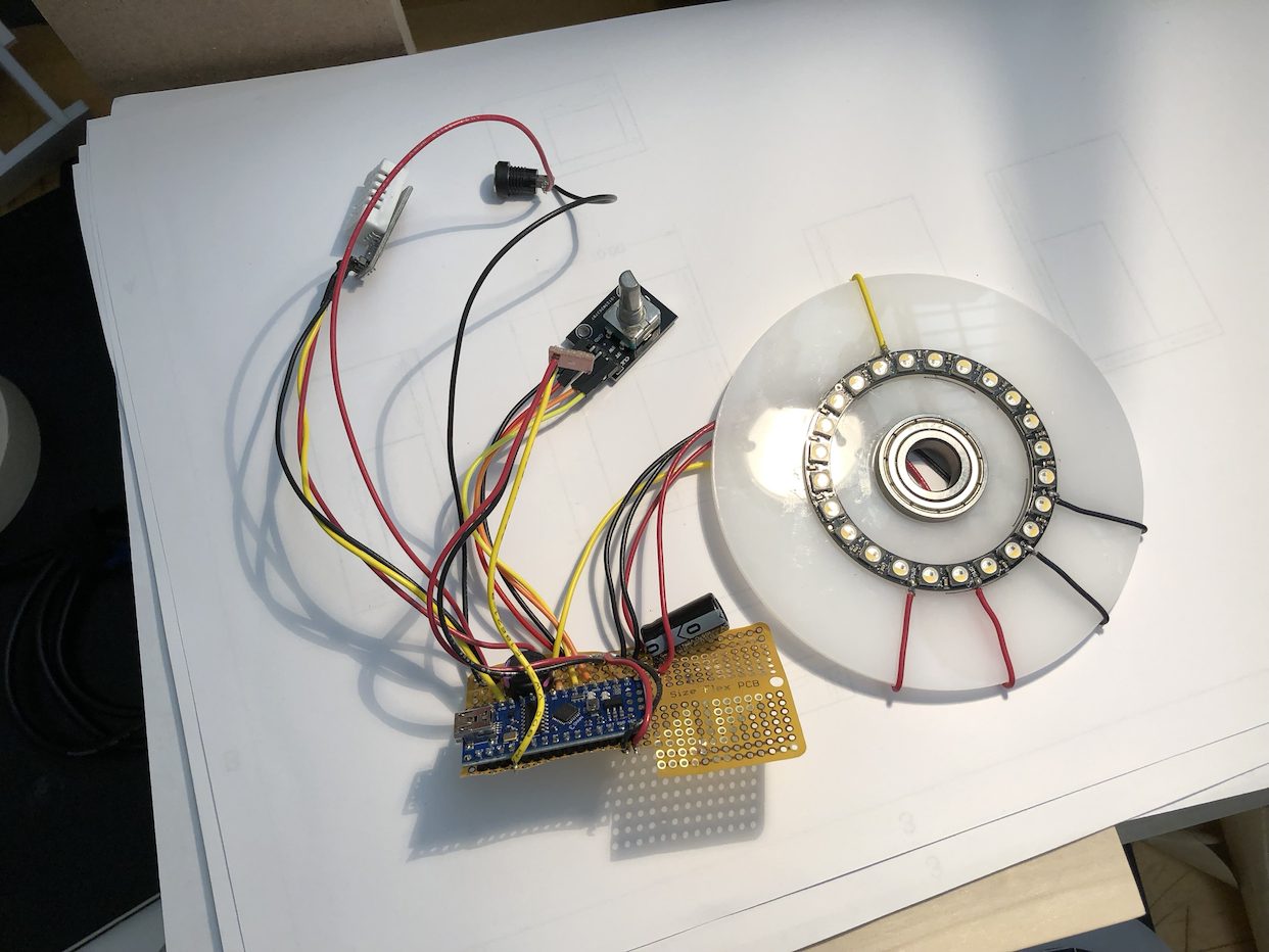
The basic components (DHT and ambient light sensors, NeoPixel Ring, rotary encoder) connected to an Arduino. The rotary encoder pictured was used for testing and verification and was replaced with a smaller one later.
Because everything had to fit inside an enclosure approximately 5″ x 5″ x 1.25″, minimizing the footprint of every component and connection was key. I tried to use an ATTiny85 to handle and control all the components but was unable to get it to drive the NeoPixel in a reasonable amount of time, so I settled on using an Arduino Nano instead. While the rotary encoder pictured above had great resolution and was very robust (it’s commonly used in robotics applications), its z-height was too big to fit in the casing so I chose a smaller component instead.
Working out the programming with all components proved to be a challenge, even without the fuss of the ATTiny85. Appropriately sequencing and implementing logic was essential in managing all the possible modes of the system, while controlling the NeoPixel was essential in making visual feedback polished and natural. The pulsing of the LEDs is accomplished with a sine function, a smoothing algorithm ensures that sudden changes in ambient light don’t noticeably affect LED output, and millis() is used in favor of delays to make the system as responsive as possible. My thanks to Eric Mendez and Robert Zacharias, who were extremely helpful in troubleshooting and explaining the logic of implementing multiple aspects.
Once I had ensured that the electronics were working as designed, I optimized the LED brightness output vis-à-vis the ambient light sensor and added a simple piezoelectric buzzer to provide auditory feedback when setting the threshold humidity, corresponding with the NeoPixel. It’s better visualized in the video below:
A quick rundown of the status LEDs:
- Blue pulsing ring – Relative humidity is below threshold humidity. The drier the air, the faster the pulsing.
- Green ring – Relative humidity is at or above threshold humidity. Appears for a few seconds, then fades.
- Individual LEDs turning on/off sequentially – Currently in edit mode; turn dial to adjust threshold humidity.
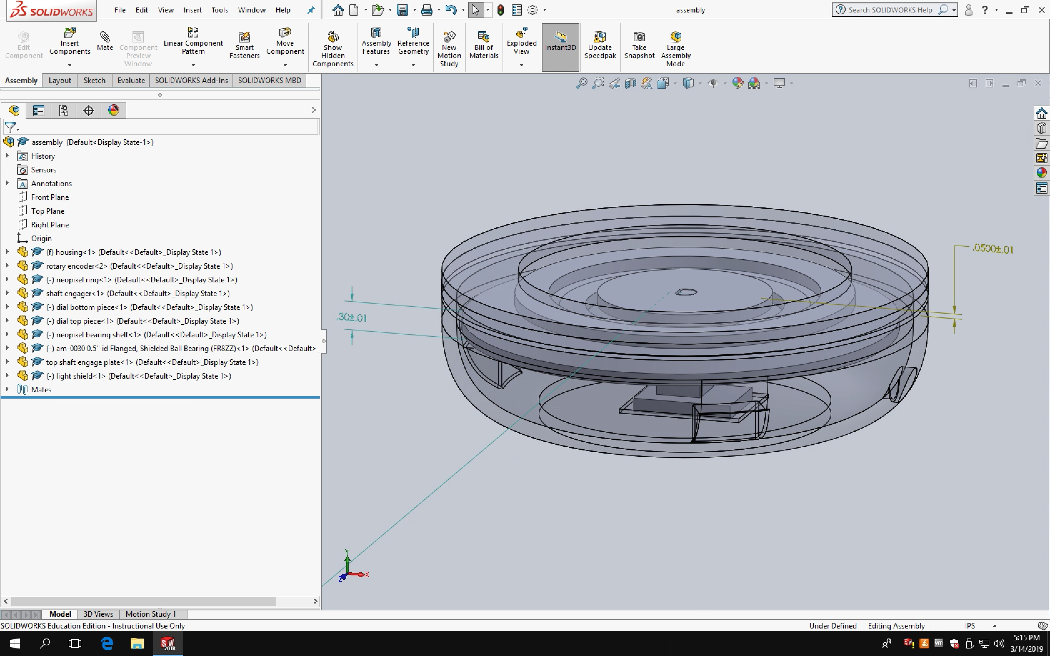
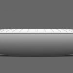
At the same time, I worked on designing an enclosure that would house all the components and also support the humidifier. Sketches of different profiles and arrangements of components gradually yielded a CAD model, seen below.
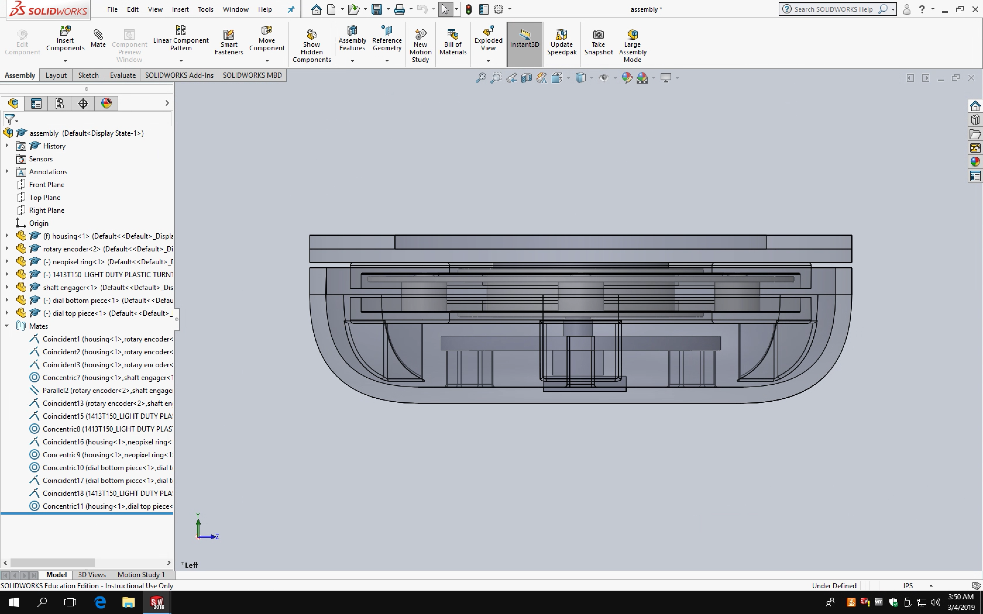
Space is a premium in the first “final” enclosure design.
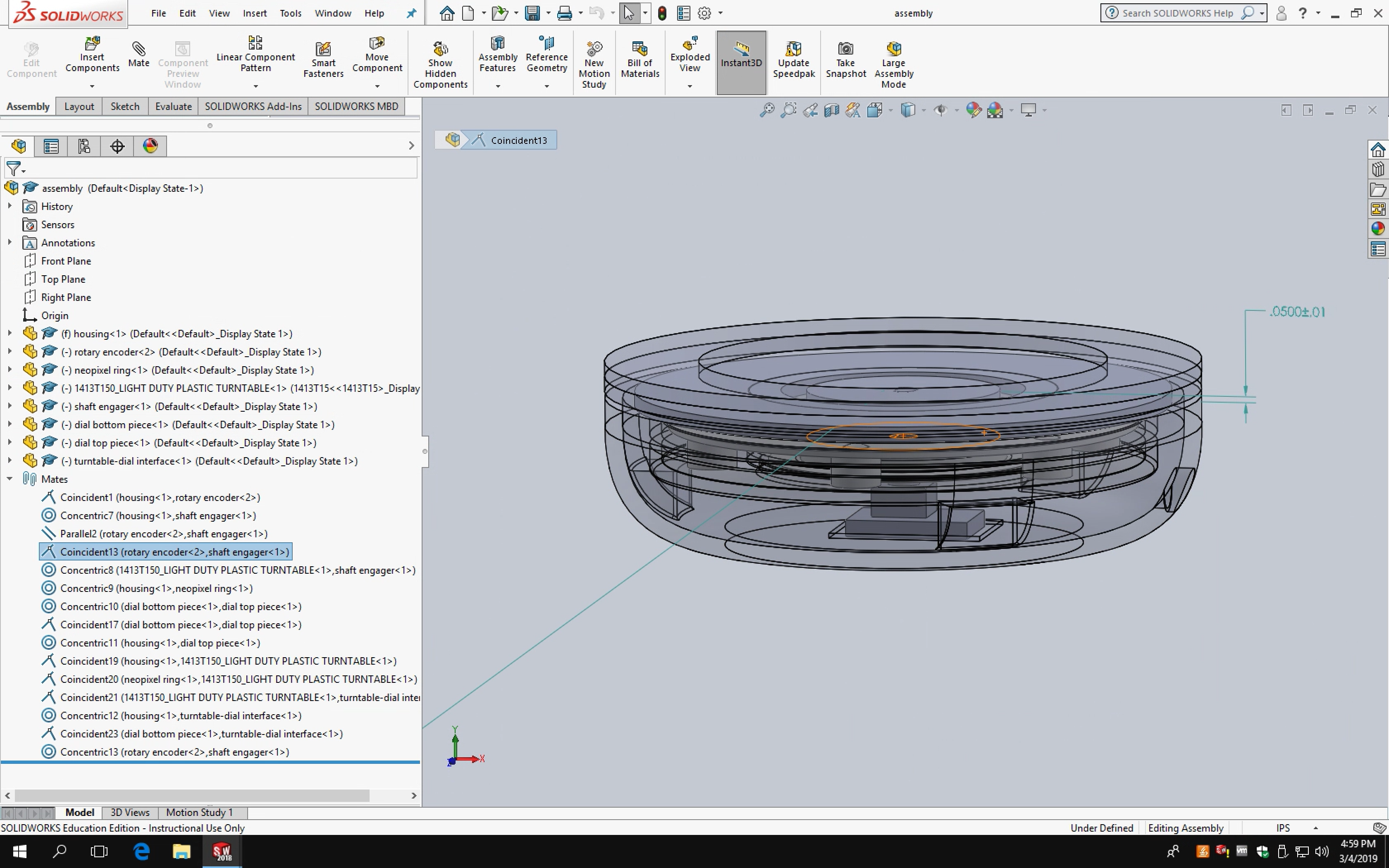
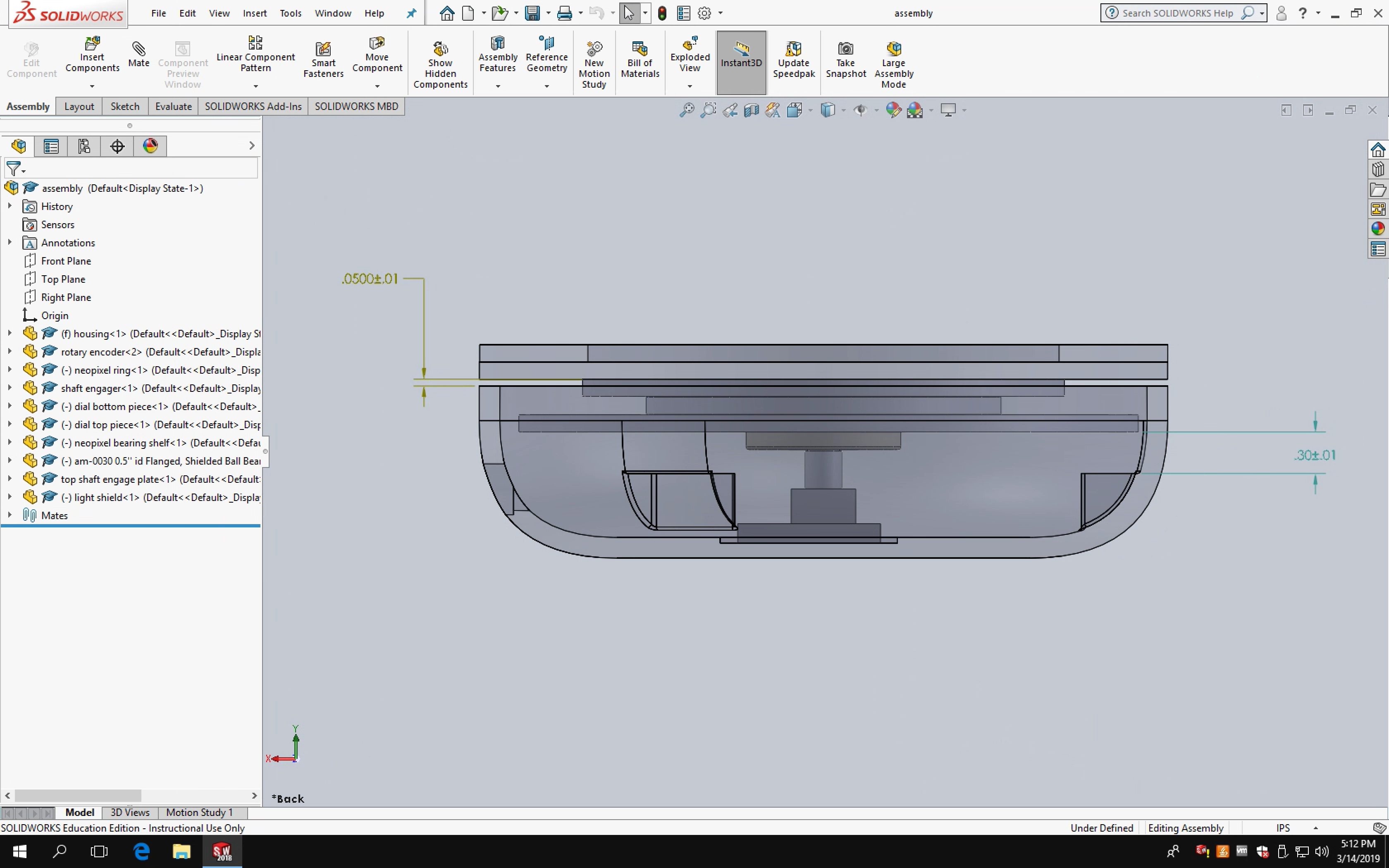
I counted on a turntable from McMaster-Carr to be transparent like on the website (it was white). Since this arrangement had the NeoPixel directly under the turntable, I had to redesign almost all the internal components to use a different bearing. A positive side effect was that being forced to use a different bearing meant that I could use a smaller component, freeing up valuable space inside the enclosure.
With the enclosure design pretty much set, I 3D-printed and laser cut components. I originally wanted to use an SLA printer, but given that this was the first print (Form 2 prints are expensive) and the specific resin I wanted wasn’t available, I used a traditional FDM printer instead. With a little modification, the housing can also be made of wood and turned on a lathe.
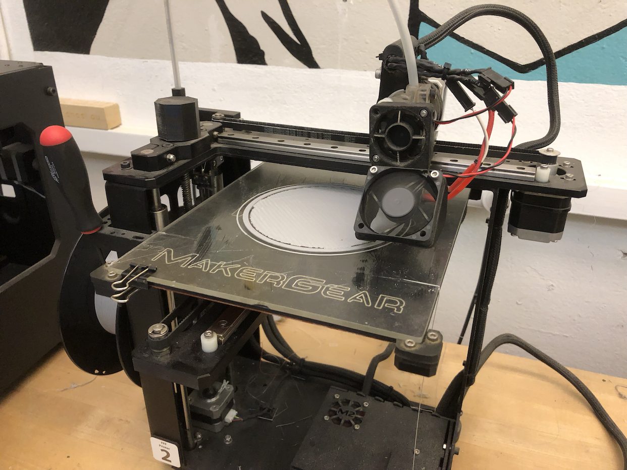
During printing.
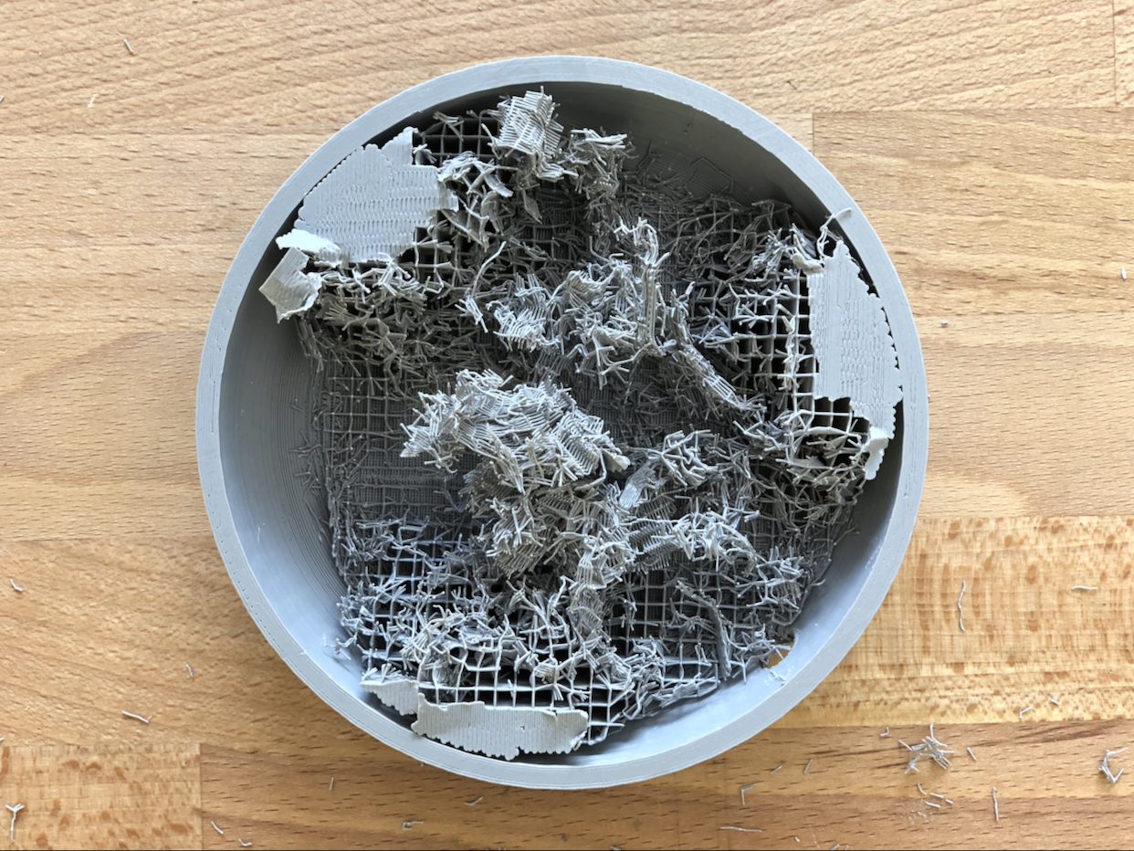
Post-print. Breaking off all the supports took some time.
Other parts of the enclosure, including the top dial, were made from laser cut acrylic derived from the same CAD file. Since the enclosure has a circular profile with a rotary encoder at the center, carefully aligning differently-sized components to be concentric was essential.
Bringing together the sub-assemblies of the enclosure.
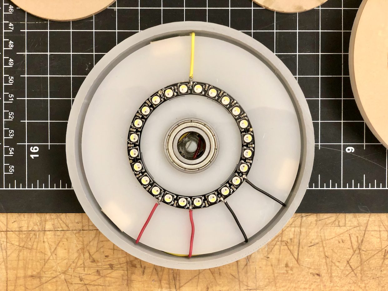
Testing fit of the the NeoPixel-wiring-bearing subassembly within the enclosure.
With the enclosure parts made, it was time to transfer the electronics inside. I soldered them to a flexible PCB, thinking that the flexibility and easy resizability of the board would help fit all the parts inside the housing. However, testing upon solder completion revealed that the connections were already compromised. The PCB is able to flex, but I hadn’t considered that flexing solder points would eventually cause them to crack and separate from the board. In the end, the electronics would only function intermittently if held at extreme angles.
Soldering right components with rigid solder to a flexible PCB was not a good idea.
I had to rewire everything, including a new Arduino Nano to a new rigid PCB which I cut down to size. Luckily, everything still fit inside the housing.
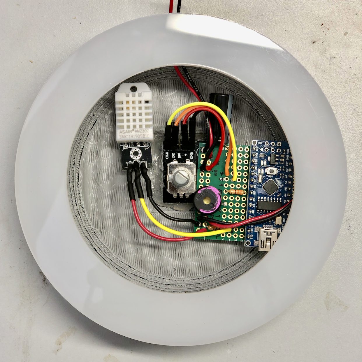
In the process of rewiring components to a new (rigid) PCB.
In all previous steps, the Nano accepted code upload fine and functioned as designed. Other people in the class had run into issues with uploading to the Nano and electrical faults, but I had yet to experience these issues until everything (including the new Nano) was soldered together. I had tested this Nano with the Blink sketch and my code prior to transferring everything from a breadboard to the PCB and it performed as expected, but once I had finished soldering and needed to reupload my code, it failed.
Fortunately, I was able to upload the code with a Windows PC. Afterwards, I assembled the base.
Photos
-
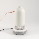
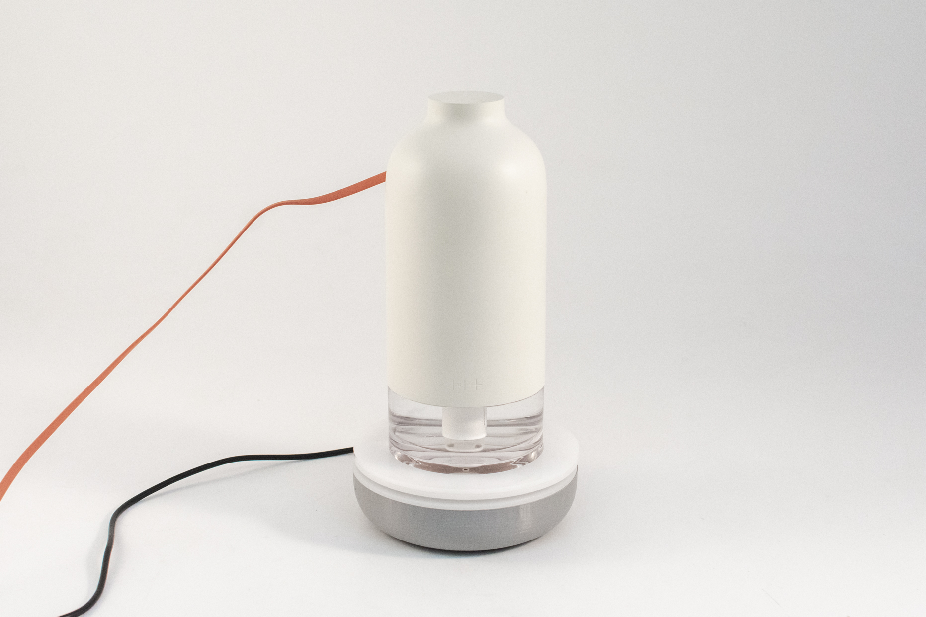
- Humidifier on base.
-
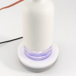
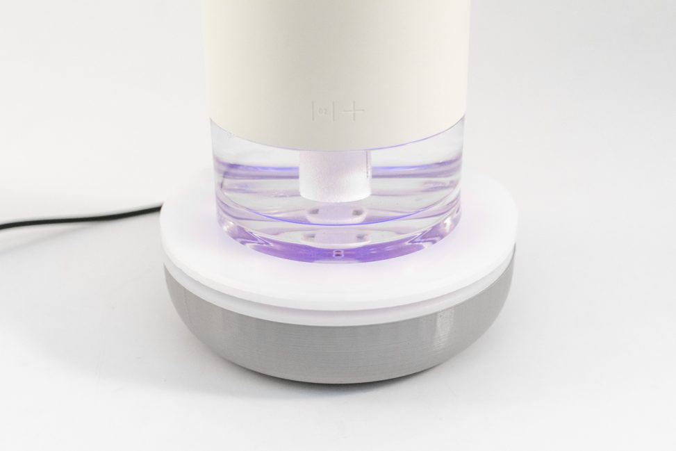
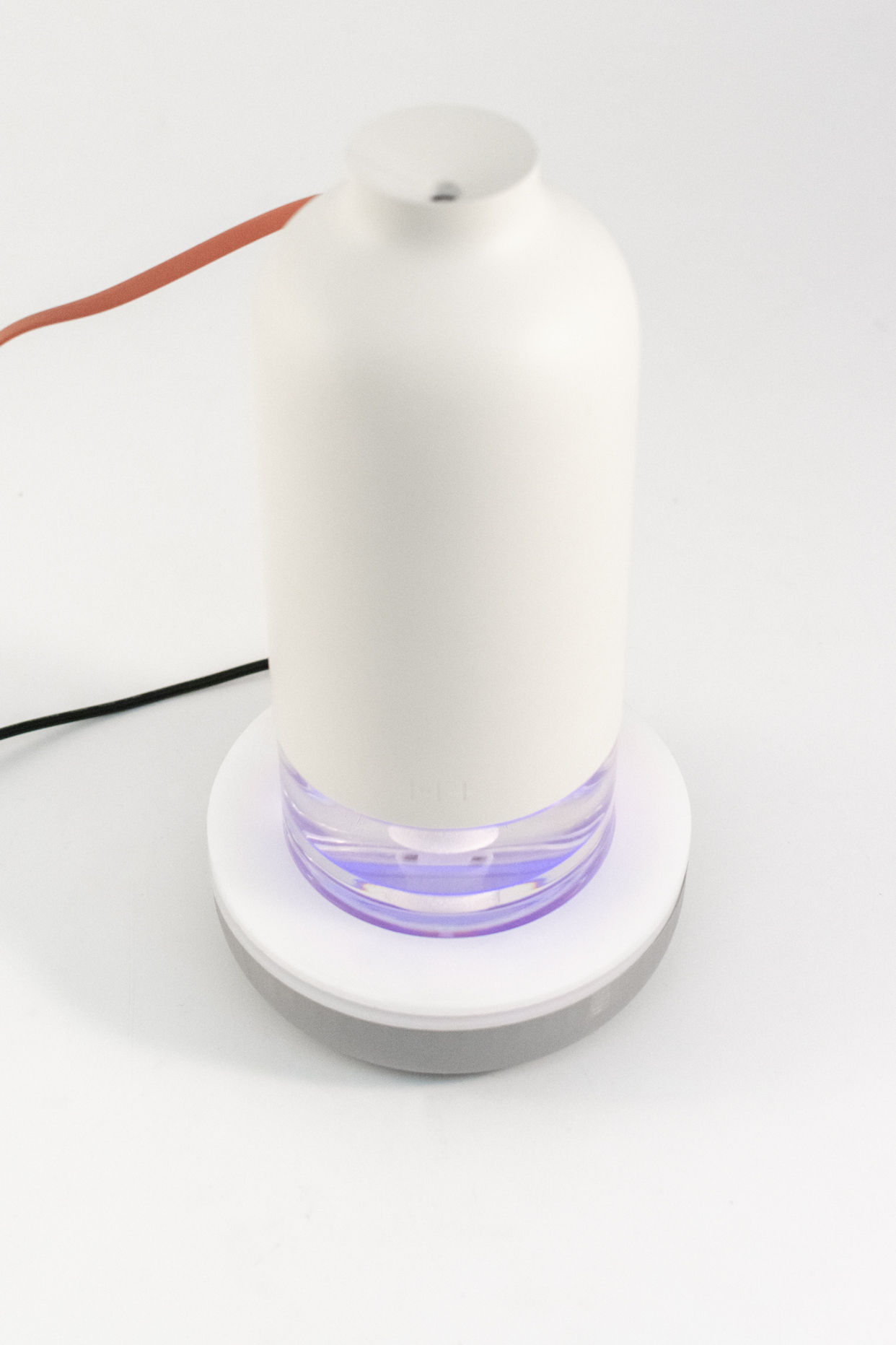
- LED illumination is visible through the humidifier.
-
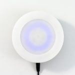
- A ring of LEDs serves as a display.
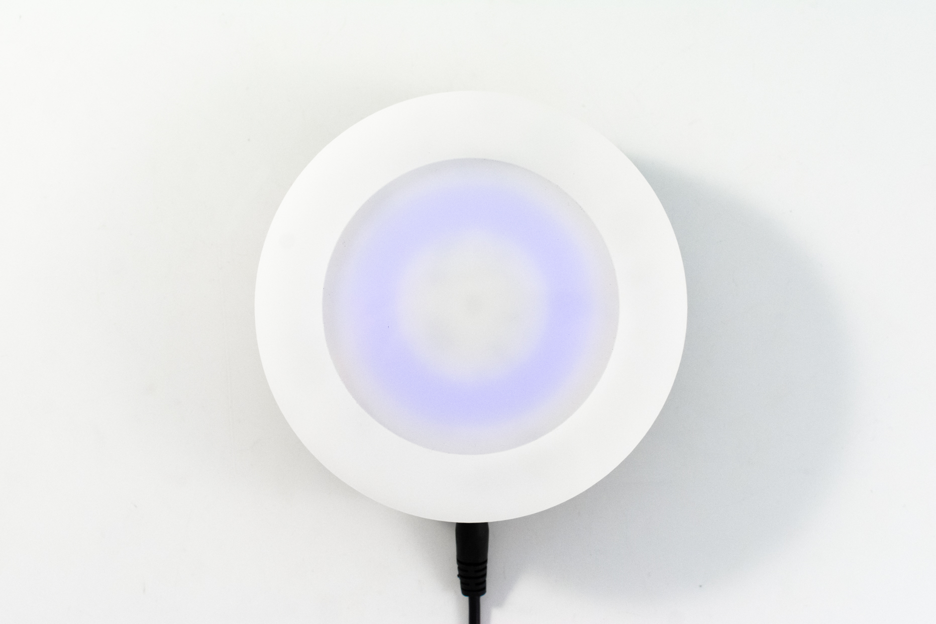
-
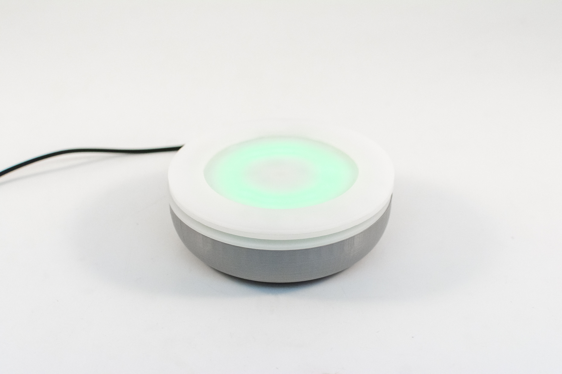
- When the humidity in a room reaches a set threshold, the LEDs turn green.
-
- Side view.
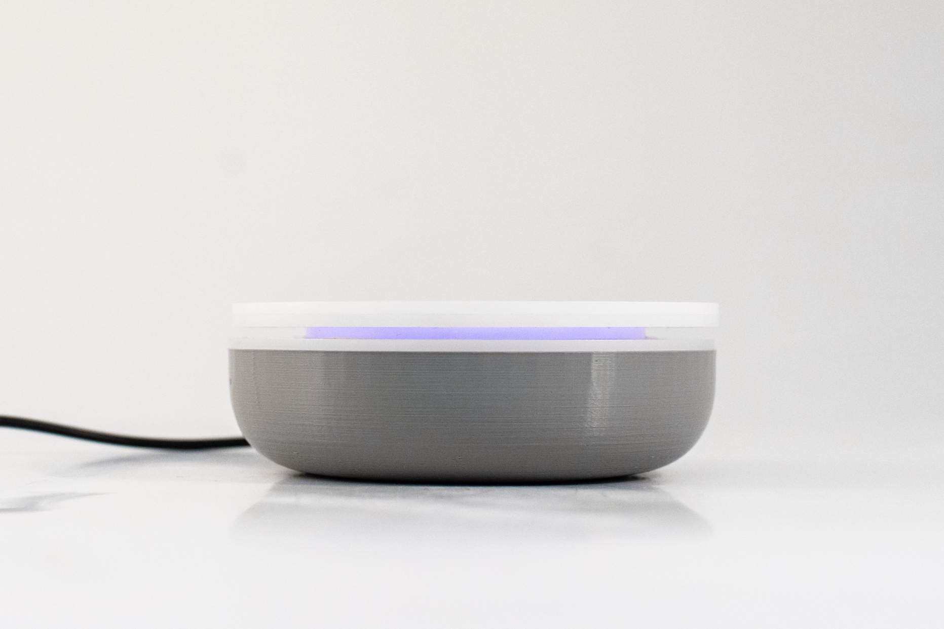
-
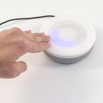
- To adjust the threshold humidity, spin the top dial.

A pulsing blue pattern indicates that it’s currently drier than the set threshold.
To adjust the threshold humidity, spin the top dial. If the relative humidity is at or above the threshold, a green pattern is visible.
Discussion
Response
“Could there be a component that controls the ticking sound (ie on/off)?”
I can see how a clicking sound would be undesirable in certain situations, but the piezoelectric buzzer used is so quiet (especially when contained in the enclosure) that it probably won’t be an issue. It’s quieter than the Home button sound effect in iPhone 7 and 8.
“So one question I have is it’s a good idea for this to be something that you have to remove the humidifier to see/interact with? Would it be better if you could see the lights when the humidifier is docked?”
In theory one would not frequently adjust the threshold humidity once it’s set and the humidifier is quite small and light (about the size of a water bottle) that it’s easy to take off, adjust the threshold on the base, and put back on top. The base of the humidifier is clear plastic so the LEDs are visible when on.
Self critique
I’m quite relieved that this project eventually worked after several significant hardware failures and challenges. I wanted to make the humidifier base to the best of my ability so that I could include it in my portfolio, so I spent considerable time on programming, design, and fabrication. As an early iteration, the physical design of the base could use many refinements – I already have some sketches and CAD files of forms I think would work better – but I’m glad I eventually reached the goal of having a physical base that functions as envisioned.
What I learned
In the future I will definitely avoid flexible PCBs in my projects.
Balancing objectives for the code took quite some time. For example, I wanted to use a smoothing function tying the ambient light sensor (ALS) readings to the LED outputs, but the particular array implementation I was trying requires multiple readings in order to establish an average that reflects current conditions. Normally, this wouldn’t be an issue since the ALS readings happen very quickly, but because of the sin function used to control LED pulsing, ALS readings were delayed and thus the LEDs would only very slowly increase brightness when the device was first plugged in.
When depending on many different manufactured parts from many different vendors, sometimes a part does not function or look as described. I had a few of these obstacles pop up over the course of this project and had to redesign around those constraints. While not ideal, these issues pop up quite frequently during the manufacturing and assembly of actual products (unless every component is designed and manufactured in-house). As an industrial design student, handling these issues provided a valuable learning experience. I can attest that “hardware is hard.”
Next steps
The most immediate next step is to refine the design of the enclosure to be more cohesive. I’ve already started sketching and modeling more developed forms, continuing to think about materials and finishes that would serve the product well.
Now that I know how all the electronic components inside are wired and function, I could also, in the future, design a custom PCB that would be mounted in the housing and connect all the components together. This would do away with messy and unreliable wires jumping from a small rectangular board to components situated all around and serve to make the product more robust and refined internally.
Finally, while the NeoPixel Ring functioned very well, it is sold in only a few sizes. Thus, while the outer diameter of the base measures 5″, the LED ring is quite a bit smaller. I would have liked for the LEDs to be closer to the outer edge of the enclosure. With a custom assembly of LEDs this would theoretically possible, but I’ve already had so much trouble wiring existing components that creating an entirely new and complex electronic part would be something very far down the road.
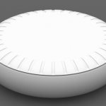
Renders of a new design.
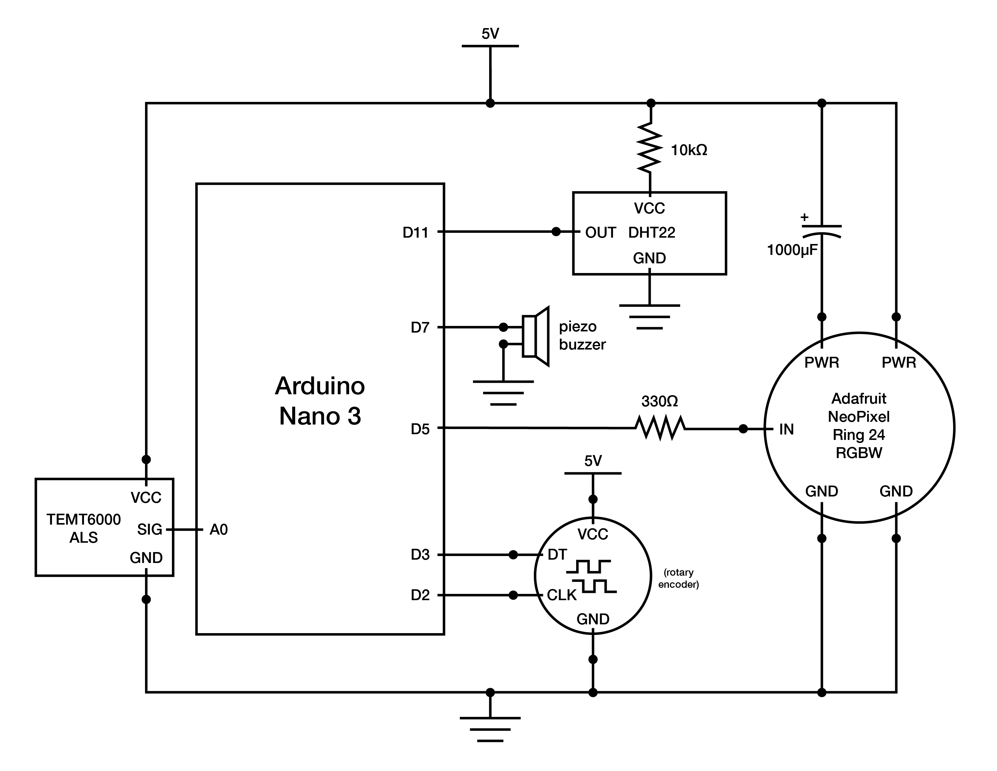
Schematic
Code
/* Humidifier Base
 *
 * Ian Shei
 *
 * Description: Implements functionality for a custom-designed humidifier base
 * that reads the relative humidity in a room. If the humidity is lower than the
 * set threshold, LEDs mounted near the top of the base will pulse to notify the
 * user to turn on the humidifier – the faster the pulsing, the drier then air.
 * One can set the threshold humidity by turning the dial forming the top of the
 * base, with visual and auditory feedback from the LEDs and a speaker,
 * respectively. Once the relative humidity meets the threshold, the LEDs will
 * turn green for a few seconds then turn off, indicating that the humidifier no
 * longer needs to be on.
 *
 * Adafruit NeoPixel implementation adapted from Adafruit_Neopixel library.
 * Available via https://learn.adafruit.com/adafruit-neopixel-uberguide/arduino-library-installation.
 *
 * DHT sensor implementation adapted from Adafruit DHT sensor library. Available
 * via https://learn.adafruit.com/dht/using-a-dhtxx-sensor.
 *
 * mapfloat function adapted from user "skumlerud" on forum.arduino.cc. Available
 * via http://forum.arduino.cc/index.php?topic=3922.0.
 *
 * Smoothing implementation adapted from David A. Mellis & Tom Igoe's example at
 * http://www.arduino.cc/en/Tutorial/Smoothing.
 *
 * millis() rollover implementation adapted from James Lewis' example at
 * https://www.baldengineer.com/arduino-how-do-you-reset-millis.html.
 *
 * Piezoelectric tick implementation adapted from user "el_supremo" on
 * forum.arduino.cc. Available at https://forum.arduino.cc/index.php?topic=299032.0.
 *
 * LED pulsing implementation adapted from MikeGrusin's Sparkfun tutorial.
 * Available at https://www.sparkfun.com/tutorials/329.
 *
 * Encoder implementation adapted from Paul Stoffregen's Quadrature Encoder Library
 * for Arduino. Available at https://github.com/PaulStoffregen/Encoder.
*/

#include "DHT.h"
#include "math.h"

#include <Adafruit_NeoPixel.h>
#ifdef __AVR__
  #include <avr/power.h>
#endif

// setting up encoder
#include <Encoder.h>
long previous; // previous position reading of encoder
long current; // current position reading of encoder
int ledIndex = 11; // 24 LEDs in NeoPixel Ring. By default, the threshold humidity is set at 50% (hence index of 11).
int thresholdLed = 0; // thresholdLed takes value of ledIndex when ledIndex is changed
Encoder myEnc(2, 3);

// setting up NeoPixel, DHT sensor, ambient light sensor, speaker pins
#define STRIPPIN 5 // NeoPixel Ring
#define DHTPIN 11
#define DHTTYPE DHT22
#define LIGHTSENSORPIN A0
#define TICK_PIN 7

Adafruit_NeoPixel strip = Adafruit_NeoPixel(24, STRIPPIN, NEO_GRBW + NEO_KHZ800);

DHT dht(DHTPIN, DHTTYPE);

float pulseIncrement = 0; // adjusts the speed at which LEDs pulse
bool editMode = false; // currently editing threshold or not
bool greenOn = false; // is the green LED pattern (indicates relative humidity has met threshold) on?
bool afterTrigger = false; // if relative humidity is at or higher than threshold, green LED pattern will show and afterTrigger will be true
float h; // humidity

// mapfloat functino returns float values
float mapfloat(float x, float in_min, float in_max, float out_min, float out_max) {
  return (x - in_min) * (out_max - out_min) / (in_max - in_min) + out_min;
}

unsigned long markMillis = 0; // marks time at which last input has taken place

// setting up smoothing of ambient light sensor (ALS) readings
const int ambientNumReadings = 100;
int ambientReadings[ambientNumReadings];
int ambientReadIndex = 0;
int ambientTotal = 0;
float ambientAverage = 0;
float percent_ambient;

void setup() {
  Serial.begin(9600);

  dht.begin();
  h = dht.readHumidity();

  strip.begin();
  strip.setBrightness(50);
  strip.show(); // Initialize all pixels to 'off'

  pinMode(LIGHTSENSORPIN, INPUT);

  // ALS smoothing
  for (int thisAmbientReading = 0; thisAmbientReading < ambientNumReadings;
  thisAmbientReading++) {
    ambientReadings[thisAmbientReading] = 0;
  }
}

void loop() {
  // ALS smoothing
  ambientTotal = ambientTotal - ambientReadings[ambientReadIndex];
  ambientReadings[ambientReadIndex] = analogRead(LIGHTSENSORPIN);
  ambientTotal = ambientTotal + ambientReadings[ambientReadIndex];
  ambientReadIndex = ambientReadIndex + 1;

  if (ambientReadIndex >= ambientNumReadings) {
    ambientReadIndex = 0;
  }
  ambientAverage = abs((ambientTotal / ambientNumReadings) / 1023.0);
  percent_ambient = abs(analogRead(LIGHTSENSORPIN) / 1023.0);

  float in, out; // in defines the starting and ending position of the LED pulsing sin function seen later; out is LED brightness output

  unsigned long currentMillis = millis(); // current time

  // encoder implementation
  previous = current;
  current = myEnc.read() / 3.33333333;

  if(previous != current) { // if encoder position has changed enter threshold edit mode
    editMode = true;
  }

  if(editMode) {
    for (int n = 0; n < strip.numPixels(); n++) {
      strip.setPixelColor(n, 0, 0, 0, 0);
    }

    if(previous > current) {
      if (ledIndex < 23) {
        ledIndex++;
          tone(TICK_PIN, 20000, 1); // tick sound effect whenever an LED turns on or off

        markMillis = currentMillis;
      }
    }

    if (previous < current) {
      if (ledIndex > 0) {
        ledIndex--;
          tone(TICK_PIN, 20000, 1);

        markMillis = currentMillis;
      }
    }

    for (int i = 0; i <= ledIndex; i++) {
      strip.setPixelColor(i, 0, 0, ambientAverage * 255, 0);
    }
    strip.show();

    for (int i = ledIndex; i >= 0; i--) {
        strip.setPixelColor(i, 0, 0, 0, 0);
    }
    thresholdLed = ledIndex;

    if((unsigned long)(currentMillis - markMillis) >= 4000) { // if it has been 4 seconds since last encoder input, exit edit mode
      markMillis = currentMillis;
      editMode = false;
    }

    greenOn = false; // green LED pattern does not show in edit mode
    afterTrigger = false; // resets so that if relative humidity is at or higher than threshold after editing, LED pattern can show after exiting edit mode
  }

    float t = dht.readTemperature(); // temperature readings for possible future extension
    h = dht.readHumidity();
    float f = dht.readTemperature(true);

  if(!editMode) {
    if (isnan(h) || isnan(t) || isnan(f)) {
      Serial.println(F("Failed to read from DHT sensor!")); // outputs to serial in case DHT sensor fails or is disconnected
      return;
    }

    if(h <= map(ledIndex, 0, 23, 0, 100) && h >= 0) { // if humidity is lower than threshold, pulse LEDs
      pulseIncrement = mapfloat(h, 0, map(ledIndex, 0, 23, 0, 100), 0.015, 0.005); // the lower the relative humidity is, the faster the LEDs will pulse

      for(in = 1.5 * M_PI; in < 3.5 * M_PI; in = in + pulseIncrement) // sin(1.5pi) = -1, period ends at 3.5 pi such that LEDs are off -> on -> off
      {
        out = sin(in) * 127.5 + 127.5; // sin extrema are -1 and 1 such that out = [0, 255] corresponding to LED brightness output

        if (percent_ambient <= 0.05) { // if it is really dark (e.g. ALS reading = 0), manually control LED brightness so that LED output is still visible
          for (int n = 0; n < strip.numPixels(); n++) {
            strip.setPixelColor(n, 0, 0, out * 0.05, 0);
          }
        }

        else {
          for (int n = 0; n < strip.numPixels(); n++) {
            strip.setPixelColor(n, 0, 0, percent_ambient * out, 0);
          }
        }
        strip.show();
      }
      greenOn = false; // green LED pattern does not show in LED pulse mode
      afterTrigger = false; // resets so that if relative humidity is at or higher than threshold after editing, LED pattern can show
    }

    else if (!greenOn){ // if relative humidity >= threshold, show green LEDs
      for(in = 1.5 * M_PI; in < 2.5 * M_PI; in = in + 0.005) {
        out = sin(in) * 127.5 + 127.5;

        for (int n = 0; n < strip.numPixels(); n++) {
          strip.setPixelColor(n, 0, percent_ambient * out, 0, 0);
        }
        strip.show();
      }
      markMillis = currentMillis;
      Serial.println("greenOn");
      greenOn = true; // green pattern is on
    }

    // if green pattern has shown already, turn off LEDs until relative humidity no longer meets or exceeds threshold
    if(!afterTrigger && greenOn && (unsigned long)(currentMillis - markMillis) >= 4000 && h > map(ledIndex, 0, 23, 0, 100) && h >= 0) {
      for(in = 2.5 * M_PI; in < 3.5 * M_PI; in = in + 0.005) { // sin(2.5pi) = 1, sin(3.5pi) = -1 such that LEDs dim to 0 along sin curve
        out = sin(in) * 127.5 + 127.5;

        for (int n = 0; n < strip.numPixels(); n++) {
          strip.setPixelColor(n, 0, percent_ambient * out, 0, 0);
        }
        strip.show();
      }
      afterTrigger = true;
    }
  }
}
Comments are closed.