Introduction For our final project, our team was paired with an older friend, Irv, to develop a “convenience machine” he could use to improve his life. Over the course of a month, we interviewed him on his daily activities, developed a prototype , and refined a final model that Irv could take home and use. By employing methods of Physical Computing, including programming, circuitry, and physical fabrication, we created an “interactive itinerary” device unique to Irv’s busy lifestyle.
What we built The Interactive Itinerary is a digital reminder system (think Google Calendar) that feels like an analog device. The user can set alarms for tasks or events without having to type on a small and sensitive touchscreen. Instead, the user can write down the task on a piece of paper and set the alarm using built in knobs.
Outer housing of itinerary is bound with elastic. The knobs and buttons are protected by the sides but still accessible without having to open the device.
VIDEO
VIDEO
Inside of itinerary displays an LCD screen, casing for electronics, and notepad.
“Task” and “time” knobs for programming the device, indicator LED, and sliding mechanism to access electronics.
The top side of the electronics housing reveals the on/off button, “snooze” button for offsetting an alarm, and charging port.
A small manual is mounted under the notepad for troubleshooting and quick reference.
Sliding mechanism allows access to RTC for battery changes, arduino reset button, and any other troubleshooting issues.
How it’s used: On a normal day, Irv wakes up and unplugs the device from the charging port. On the notepad, he writes down his tasks for the day and the time they occur (i.e., medications, tennis meetings, cultural events). He can then use the knobs on the device to set reminders for the tasks he would like to be reminded of. Irv then closes the journal and takes it with him throughout the day. When a reminder goes off, the journal will buzz and flash, and the task will appear on screen. He can then press a button to turn off the alert, or push “snooze” to delay the reminder for another 15 minutes.
How we got here Following the formative critique phase of this project, our team created a list of milestones we intended to hit for our final meeting with Irv. After showcasing our first prototype at the formative critique to Irv, we learned that a 15 minute snooze button would be a useful addition to the device. We learned that Irv preferred to set alarms in military time and would like an on/off switch on the device to conserve power.
We created a to do list with Irv to ensure that the final product suits his needs and ranked it based on importance.
The snooze button and on/off button were relatively easy to set up. The most important part about the snooze and on/off button is picking a button that has the right tactile feeling. After the formative critique, we went to the physical computing lab and pulled out many button options for Irv to test. He settled on a red momentary push button for the snooze button and a black latching push button for the on/off switch.
Irv tests different buttons for the new features on his interactive itinerary.
The next thing we wanted to add to the interactive itinerary is displaying the task “home page” when the alarm for that task goes off. This feature, which wasn’t in our first iteration, makes sense because when the alarm goes off, we would want to know which task alarm was going off. So, when the alarm goes off now, the task number that is ringing is also displayed on the LCD. Without this feature, the user would have to look at the written list of tasks and check each alarm time to see which task was going off.
In order to manage all our coding iterations and keep track of our goals, we wrote comments on our new versions to communicate what was working, what wasn’t, and what our next steps should be.
To make the device portable, we intended to make the device battery powered. We ordered a lithium ion battery and a chip so that Irv can charge the device at night. The chip ensures that the battery charges without overcharging the lithium ion battery. After setting up the battery, we soldered the on/off switch to the battery, which acts as an on/off switch for the device. SInce the lithium ion battery is quite large, our goal to make the device smaller was getting harder.
Once all the necessary components were bought and collected, we laid out the device components to determine the best way to stack the device to minimize the space. As shown in the picture below, the device would already be very cramped, even before soldering everything together. Since we were no longer considering bootloading our device onto a smaller device, we had to stick to the arduino uno. So at this point in the process, our goal to make the device “pocket-sized” was becoming less and less feasible.
In an ideal set up, the LCD screen would sit at the top of the device. The charging port is in the top left of the box. The snooze button and the on/off button would rest on the top, closer to the spine of the box.
While we knew what the general layout of our itinerary would be, we explored ways we could configure the electronic and tactile components to save space. We also thought of ways we could construct a sliding mechanism with lasercut material that would allow the electronics to be accessible without force.
While designing the prototype for the device casing, we considered several materials for the electronic housing. Acrylic, while sturdy and aesthetically pleasing, is prone to shattering. So if Irv decided to put this device in his back pocket, or applied too much pressure to it, it might crack under pressure, rendering the casing useless. Styrene is a plastic that is a bit more flexible but sturdy as well. Ultimately, styrene would not have been ideal to use as our electronic casing because we needed to make a case that had precise cuts and we would not be able to laser cut styrene. So, we decided that ⅛” birch plywood was the best material to use for the device. We also decided to include a sliding lid on the electronic casing so that if Irv needed to replace the RTC battery or reset the arduino to troubleshoot.
The sliding mechanism consisted of two pieces of plywood glued together that fit into the top facing of the case. To keep the lid on, a support bar was built under the top facing. That way, the lid can rest on the support bar.
In addition, the laser cutters at TechSpark burn more, cut slower, and are more volatile than the laser cutters in IDeATe. Luckily, the first print was just a prototype; so we planned on printing the final casing in IDeATe. The first prototype was also larger than we needed. There was a lot of room inside the casing. We were able to make the case thinner and narrower. While the notebook would still not be pocket-sized, it was still considerably smaller.
After considering different methods of fabrication for the outer casing, we decided traditional “bookbinding” techniques would best fit Irv’s aesthetic. Inspired by moleskine journals, we used flexible chipboard, faux leather, and elastic to create a housing that would be sturdy, comfortable, and stylish.
Conclusion After the final crit, we added one last feature to our box because of a comment made to “make the alarm stronger” if it couldn’t be kept in his pocket. Since we were planning to make the box small, we didn’t account for possible issues if it was too large to fit into a pocket. Some of these issues would be would Irv notice the alarm going off if it wasn’t on his person. Our solution was to add a small LED next to the task and time knobs that would blink at the same rate that the buzzer would be going off. This would allow Irv to see the alarm going off as well as feel it. As he’s told us that his hearing isn’t the best, we thought we’d try to stimulate his other senses with the alarm.
Working with Irv was more than just an opportunity to gain insight on the life of an older person, but a beneficial experience in collaborating with a client. Not only did learning about Irv’s lifestyle allow us to empathize with his daily needs, it also taught us how to iterate and design under constraints that can assist virtually anyone. While the itinerary was developed for his particular lifestyle and activities, all of us can benefit from a method of keeping track of lists with time notifications. In principle, this project was a great introduction to universal design. By solving the problems of overlooked populations rather than the “average person,” we can innovate more effectively and inclusively.
Moreover, we believe that having a person to design for other than ourselves pushed us further to create something functional and intuitive. Since we realized Irv wouldn’t have the means to fix the RTC if it reset, for example, we decided late into the project to build in a time-setting function into the program. This mindset also prompted us to add in a sliding compartment to access the electronics, a “sleep” mode to save power, and a reference manual for troubleshooting. If we hadn’t had an actual client to work with, it would have been easier to let these considerations slide when you know you can can quickly reupload, solder or glue something back together. Knowing that Irv will be keeping this in his home and hopefully trying it out, we feel more confident knowing that we built in features to extend the project’s lifespan.
Code and Files schematic
Code /* Reminder - Final Project
Eliza Pratt
Helen Yu
Eric Mendez
***********************************************************
description:
Use "Task" and "Time" button knobs to set alarms throughout the day. The LCD display shows
the current task (1 to 9) and the set alarm time. If the task button is pushed, the alarm
is turned on. There is a snooze button as well, so if you'd like to be snooze the alarm, the
button adds 15 min to the on-going alarm. The display will reflect that the alarm was snoozed.
Pin mapping:
- The task and time knobs have 3 input pins each and those are pins 2-7
- The snooze button is 8
- The buzzer pin is 9
- The pin for the LED is 11
- The SCA/SCL pins are used on both the LCD screen and RTC (real time clock)
- If adding a Lipo battery and power regulating chip (see our schematic)
- use a switch to interupt the connection from the chip to Vin on the Arduino
example code used:
- Used examples from TimeLib, LiquidCrystal, DS1307RTC, and Encoder to help set up
their usage in this project.
***********************************************************
*/
#include <Wire.h>
#include <TimeLib.h>
#include <LiquidCrystal_I2C.h>
#include <DS1307RTC.h>
#include <Encoder.h>
// set up lcd
LiquidCrystal_I2C screen ( 0x27 , 16 , 2 );
// time elements
tmElements_t tm ;
Encoder taskKnob ( 2 , 4 );
Encoder timeKnob ( 3 , 6 );
// task and time knobs / buttons
const int TASK_BUTTON = 5 ; // yellow wire
const int TIME_BUTTON = 7 ; // yellow wire
const int SNOOZE_BUTTON = 8 ; // white wire
const int MOTORPIN = 9 ;
const int LEDPIN = 11 ;
long oldTaskPosition = - 999 ;
long oldTimePosition = - 999 ;
unsigned long motorTimer = 0 ;
unsigned long screenLight = 0 ;
bool motorState = false ;
bool oldTimeState = false ; // stores button state
bool oldTaskState = false ; // stores old button state (time)
bool oldSnoozeState = false ; // stores old button state (snooze)
// task
int task_pos = 0 ; // dial position
int time_pos = 0 ; // time dial position
int currentBuzz = - 1 ;
// stores task position that is currently buzzing (-1 = nothing)
int timeMax = 24 ; // limit for dial turn (changes for hours/min/am-pm)
int timeButtonCount = 0 ; // hours/minutes/ampm
int lcdHour = 0 ; // for printing hour on LCD screen
int lcdMinute = 0 ;
int lcdTask = 0 ;
int rtcHour = 0 ;
int rtcMinute = 0 ;
// for each task (10 tasks)
int alarmHour [] = { 12 , 12 , 12 , 12 , 12 , 12 , 12 , 12 , 12 , 12 };
int alarmMinute [] = { 0 , 0 , 0 , 0 , 0 , 0 , 0 , 0 , 0 , 0 };
int alarmOn [] = { 0 , 0 , 0 , 0 , 0 , 0 , 0 , 0 , 0 , 0 };
bool snoozeOn [] = { false , false , false , false , false , false , false , false , false , false };
void setup () {
pinMode ( MOTORPIN , OUTPUT );
pinMode ( TASK_BUTTON , INPUT_PULLUP );
pinMode ( TIME_BUTTON , INPUT_PULLUP );
pinMode ( SNOOZE_BUTTON , INPUT_PULLUP );
pinMode ( LEDPIN , OUTPUT );
Serial . begin ( 9600 );
setSyncProvider ( RTC . get ); // the function to get the time from the RTC
screen . init ();
screen . backlight ();
}
void loop () {
//------------------------------------
// Snooze
//------------------------------------
int snoozeState = digitalRead ( SNOOZE_BUTTON ); // task: enabled or not
if (! snoozeState && oldSnoozeState ) {
screenLight = millis ();
Serial . println ( "SNOOZE" );
if ( currentBuzz > - 1 ) {
if ( alarmMinute [ currentBuzz ] < 45 ) {
alarmMinute [ currentBuzz ] += 15 ;
} else {
// alarmMinute[currentBuzz] >= 45
alarmHour [ currentBuzz ] += 1 ;
alarmMinute [ currentBuzz ] += ( currentBuzz - 45 );
}
snoozeOn [ currentBuzz ] = true ;
currentBuzz = - 1 ;
}
}
oldSnoozeState = snoozeState ; // button thing
//------------------------------------
// Buzz Alarm
//------------------------------------
// loops through tasks
for ( int i = 0 ; i < 10 ; i ++) {
// checking if alarm needs to be activated
if ( hour () == alarmHour [ i ] && minute () == alarmMinute [ i ] && alarmOn [ i ] == 1 ) {
screen . backlight ();
buzzing (); // pulses motor
Serial . println ( "ALARM ON" );
currentBuzz = i ; // save task position of current alarm going off
}
}
if ( currentBuzz == - 1 ) {
analogWrite ( MOTORPIN , 0 );
digitalWrite ( LEDPIN , LOW );
}
taskFunction ();
taskButton ();
//---------------------------------------
// Time knob
//---------------------------------------
if (!( timeButtonCount % 3 == 0 )) {
int timeKnobMax = ( timeMax ) * 4 ;
long newTimePosition ;
// account for 4 times extra readings
if ( timeKnob . read () > timeKnobMax ) timeKnob . write ( 0 );
else if ( timeKnob . read () < 0 ) timeKnob . write ( timeKnobMax );
newTimePosition = timeKnob . read ();
//TIME IS CHANGED
if ( newTimePosition != oldTimePosition ) {
screenLight = millis ();
oldTimePosition = newTimePosition ;
time_pos = oldTimePosition / 4 ;
Serial . println ( time_pos );
}
} else {
timeKnob . write ( 0 );
}
//------------------------------------
// Time button
//------------------------------------
//Read time button
int timeState = digitalRead ( TIME_BUTTON );
if (! timeState && oldTimeState ) {
screenLight = millis ();
screen . clear ();
Serial . print ( "LCD hour: " );
Serial . println ( lcdHour );
timeKnob . write ( 0 ); // reset time knob position back to 0
// display correct task and alarm time corresponding for that task
if ( task_pos < 9 ) {
if ( timeButtonCount % 3 == 1 ) alarmHour [ task_pos ] = time_pos ;
else if ( timeButtonCount % 3 == 2 ) alarmMinute [ task_pos ] = time_pos ;
}
// RESET time mode
else if ( task_pos == 9 ) {
if ( timeButtonCount % 3 == 1 ) rtcHour = time_pos ;
else if ( timeButtonCount % 3 == 2 ) rtcMinute = time_pos ;
}
Serial . print ( alarmHour [ task_pos ]);
Serial . print ( " : " );
Serial . print ( alarmMinute [ task_pos ]);
Serial . print ( " : " );
Serial . println ( alarmOn [ task_pos ]);
timeButtonCount ++;
Serial . println ( timeButtonCount );
time_pos = 0 ;
delay ( 300 );
}
oldTimeState = timeState ;
// BUZZING
if ( currentBuzz > - 1 ) {
//display current task
lcdHour = alarmHour [ currentBuzz ];
lcdMinute = alarmMinute [ currentBuzz ];
taskKnob . write ( currentBuzz );
task_pos = currentBuzz ;
}
// set real time clock
else {
if ( timeButtonCount % 3 == 0 ) {
if ( task_pos == 9 ) {
lcdHour = rtcHour ;
lcdMinute = rtcMinute ;
} else {
lcdHour = alarmHour [ task_pos ]; // display set hour on LCD
lcdMinute = alarmMinute [ task_pos ];
}
}
else if ( timeButtonCount % 3 == 1 ) { //setting hour
timeMax = 24 ;
lcdHour = time_pos ; //displays changing hour on LCD
if ( task_pos == 9 ) {
lcdMinute = rtcMinute ;
} else {
lcdMinute = alarmMinute [ task_pos ];
}
}
else if ( timeButtonCount % 3 == 2 ) { //setting minute
timeMax = 60 ;
lcdMinute = time_pos ;
if ( task_pos == 9 ) {
lcdHour = rtcHour ;
} else {
lcdHour = alarmHour [ task_pos ];
}
}
}
screen . home ();
if ( task_pos == 9 ) {
screen . print ( "Reset Time" );
} else {
screen . print ( "Task " );
screen . print ( task_pos + 1 );
if ( snoozeOn [ task_pos ]) screen . print ( "*" );
}
screen . setCursor ( 11 , 0 );
if ( hour () < 10 ) screen . print ( "0" ); // 0 offset if < 10
screen . print ( hour ());
screen . setCursor ( 13 , 0 );
screen . print ( ":" );
if ( minute () < 10 ) screen . print ( "0" ); // 0 offset if < 10
screen . print ( minute ());
screen . setCursor ( 0 , 1 );
if ( lcdHour < 10 ) screen . print ( "0" ); // 0 offset if < 10
screen . print ( lcdHour );
screen . setCursor ( 2 , 1 );
screen . print ( ":" );
if ( lcdMinute < 10 ) screen . print ( "0" ); // 0 offset if < 10
screen . print ( lcdMinute );
screen . setCursor ( 6 , 1 );
if ( alarmOn [ task_pos ] == 1 ) { // set alarm on
// alarm on
screen . setCursor ( 13 , 1 );
if ( task_pos == 9 ) {
screen . print ( "SET" );
} else {
screen . print ( "ON" );
}
} else if ( alarmOn [ task_pos ] == 0 ) { // set alarm off
// alarm off
screen . setCursor ( 13 , 1 );
if ( task_pos == 9 ) {
screen . print ( "SET" );
} else {
screen . print ( "OFF" );
}
}
//After a minute of inactivity, turn off the LCD backlight to save power
if ( screenLight + 60000 <= millis ()) screen . noBacklight ();
else screen . backlight ();
}
//pulses motor
void buzzing () {
if ( motorTimer + 1000 <= millis ()) {
motorState = ! motorState ; //flip state
motorTimer = millis (); // reset timer
}
if ( motorState ) {
analogWrite ( MOTORPIN , 200 );
digitalWrite ( LEDPIN , HIGH );
}
else {
analogWrite ( MOTORPIN , 0 );
digitalWrite ( LEDPIN , LOW );
}
}
//TASK knob
void taskFunction () {
//Zachs method for looping the knob
if ( taskKnob . read () > 36 ) taskKnob . write ( 0 );
else if ( taskKnob . read () < 0 ) taskKnob . write ( 36 );
long newTaskPosition = taskKnob . read ();
//TASK IS CHANGED
if ( newTaskPosition != oldTaskPosition ) {
oldTaskPosition = newTaskPosition ;
screenLight = millis ();
// reset time position and button count when task is changed
timeButtonCount = 0 ;
time_pos = 0 ;
screen . clear ();
//print task position and time set for that task
Serial . print ( "old task: " );
Serial . print ( oldTaskPosition );
Serial . print ( " / task_pos: " );
Serial . println ( task_pos );
Serial . print ( " / printing: " );
Serial . println ( newTaskPosition / 4 );
}
task_pos = newTaskPosition / 4 ;
}
/*------------------------------------
Task button
if task knob is on position 11 -
DISPLAY "RESET TIME" instead of "task 11"
use time button to set current time
hit task button to set
when pressed, rtc.setTime(hours, minutes, seconds)
------------------------------------*/
void taskButton () {
int taskState = digitalRead ( TASK_BUTTON ); // task: enabled or not
if (! taskState && oldTaskState ) {
screenLight = millis ();
// RESET time on task 10
if ( task_pos == 9 ) {
// set hour:min:sec
tm . Hour = rtcHour ;
tm . Minute = rtcMinute ;
tm . Second = 0 ;
// Apr 22 2019
tm . Month = 4 ;
tm . Day = 22 ;
tm . Year = CalendarYrToTm ( 2019 );
if ( RTC . write ( tm )) {
setSyncProvider ( RTC . get );
}
}
else { // regular alarm function
if ( snoozeOn [ task_pos ]) snoozeOn [ task_pos ] = false ;
// ***change 0 and 1 -> off and on for printing
// setting the alarm: if alarm is off, turn it on
if ( alarmOn [ task_pos ] == 0 && currentBuzz == - 1 ) {
alarmOn [ task_pos ] = 1 ;
}
//if the alarm is set as on (and not buzzing), turn it off
else if ( alarmOn [ task_pos ] == 1 && currentBuzz == - 1 ) alarmOn [ task_pos ] = 0 ;
//if alarm is buzzing, we know alarm is on, so we turn it off
if ( currentBuzz > - 1 ) {
screen . clear ();
alarmOn [ currentBuzz ] = 0 ; // disable alarm
analogWrite ( MOTORPIN , 0 ); // turn off buzzing alarm
digitalWrite ( LEDPIN , LOW );
Serial . println ( "ALARM OFF" );
currentBuzz = - 1 ;
taskKnob . write ( 0 );
}
Serial . print ( "alarm on: " );
Serial . println ( alarmOn [ task_pos ]);
// Alarm on
if ( alarmOn [ task_pos ] == 1 ) {
screen . clear ();
screen . setCursor ( 13 , 1 );
if ( task_pos == 9 ) {
screen . print ( "SET" );
} else {
screen . print ( "ON" );
}
} else if ( alarmOn [ task_pos ] == 0 ) {
// alarm off
screen . clear ();
screen . setCursor ( 13 , 1 );
if ( task_pos == 9 ) {
screen . print ( "SET" );
} else {
screen . print ( "OFF" );
}
}
delay ( 300 );
}
}
oldTaskState = taskState ; // button thing
} <span class = "com" > /* Reminder - Final Project Eliza Pratt Helen Yu Eric Mendez *********************************************************** description: Use "Task" and "Time" button knobs to set alarms throughout the day. The LCD display shows the current task (1 to 9) and the set alarm time. If the task button is pushed, the alarm is turned on. There is a snooze button as well, so if you'd like to be snooze the alarm, the button adds 15 min to the on-going alarm. The display will reflect that the alarm was snoozed. Pin mapping: - The task and time knobs have 3 input pins each and those are pins 2-7 - The snooze button is 8 - The buzzer pin is 9 - The pin for the LED is 11 - The SCA/SCL pins are used on both the LCD screen and RTC (real time clock) - If adding a Lipo battery and power regulating chip (see our schematic) - use a switch to interupt the connection from the chip to Vin on the Arduino example code used: - Used examples from TimeLib, LiquidCrystal, DS1307RTC, and Encoder to help set up their usage in this project. *********************************************************** */ </span><span class = "pln" > </span><span class = "com" > #include</span><span class="pln"> </span><span class="str"><Wire.h></span><span class="pln"> </span><span class = "com" > #include</span><span class="pln"> </span><span class="str"><TimeLib.h></span><span class="pln"> </span><span class = "com" > #include</span><span class="pln"> </span><span class="str"><LiquidCrystal_I2C.h></span><span class="pln"> </span><span class = "com" > #include</span><span class="pln"> </span><span class="str"><DS1307RTC.h></span><span class="pln"> </span><span class = "com" > #include</span><span class="pln"> </span><span class="str"><Encoder.h></span><span class="pln"> </span><span class = "com" >// set up lcd</span><span class="pln"> </span><span class = "typ" >LiquidCrystal_I2C</span><span class = "pln" > screen</span><span class = "pun" > ( </span><span class = "lit" > 0x27 </span><span class = "pun" >,</span><span class = "pln" > </span><span class = "lit" > 16 </span><span class = "pun" >,</span><span class = "pln" > </span><span class = "lit" > 2 </span><span class = "pun" > ) ;</span><span class = "pln" > </span><span class = "com" >// time elements</span><span class="pln"> </span><span class = "typ" >tmElements_t</span><span class = "pln" > tm</span><span class = "pun" >;</span><span class = "pln" > </span><span class = "typ" >Encoder</span><span class = "pln" > taskKnob</span><span class = "pun" > ( </span><span class = "lit" > 2 </span><span class = "pun" >,</span><span class = "pln" > </span><span class = "lit" > 4 </span><span class = "pun" > ) ;</span><span class = "pln" > </span><span class = "typ" >Encoder</span><span class = "pln" > timeKnob</span><span class = "pun" > ( </span><span class = "lit" > 3 </span><span class = "pun" >,</span><span class = "pln" > </span><span class = "lit" > 6 </span><span class = "pun" > ) ;</span><span class = "pln" > </span><span class = "com" >// task and time knobs / buttons</span><span class="pln"> </span><span class = "kwd" > const </span><span class = "pln" > </span><span class = "kwd" > int </span><span class = "pln" > TASK_BUTTON </span><span class = "pun" >=</span><span class = "pln" > </span><span class = "lit" > 5 </span><span class = "pun" >;</span><span class = "pln" > </span><span class = "com" >// yellow wire</span><span class="pln"> </span><span class = "kwd" > const </span><span class = "pln" > </span><span class = "kwd" > int </span><span class = "pln" > TIME_BUTTON </span><span class = "pun" >=</span><span class = "pln" > </span><span class = "lit" > 7 </span><span class = "pun" >;</span><span class = "pln" > </span><span class = "com" >// yellow wire</span><span class="pln"> </span><span class = "kwd" > const </span><span class = "pln" > </span><span class = "kwd" > int </span><span class = "pln" > SNOOZE_BUTTON </span><span class = "pun" >=</span><span class = "pln" > </span><span class = "lit" > 8 </span><span class = "pun" >;</span><span class = "pln" > </span><span class = "com" >// white wire</span><span class="pln"> </span><span class = "kwd" > const </span><span class = "pln" > </span><span class = "kwd" > int </span><span class = "pln" > MOTORPIN </span><span class = "pun" >=</span><span class = "pln" > </span><span class = "lit" > 9 </span><span class = "pun" >;</span><span class = "pln" > </span><span class = "kwd" > const </span><span class = "pln" > </span><span class = "kwd" > int </span><span class = "pln" > LEDPIN </span><span class = "pun" >=</span><span class = "pln" > </span><span class = "lit" > 11 </span><span class = "pun" >;</span><span class = "pln" > </span><span class = "kwd" > long </span><span class = "pln" > oldTaskPosition </span><span class = "pun" >=</span><span class = "pln" > </span><span class = "pun" >-</span><span class = "lit" > 999 </span><span class = "pun" >;</span><span class = "pln" > </span><span class = "kwd" > long </span><span class = "pln" > oldTimePosition </span><span class = "pun" >=</span><span class = "pln" > </span><span class = "pun" >-</span><span class = "lit" > 999 </span><span class = "pun" >;</span><span class = "pln" > </span><span class = "kwd" > unsigned </span><span class = "pln" > </span><span class = "kwd" > long </span><span class = "pln" > motorTimer </span><span class = "pun" >=</span><span class = "pln" > </span><span class = "lit" > 0 </span><span class = "pun" >;</span><span class = "pln" > </span><span class = "kwd" > unsigned </span><span class = "pln" > </span><span class = "kwd" > long </span><span class = "pln" > screenLight </span><span class = "pun" >=</span><span class = "pln" > </span><span class = "lit" > 0 </span><span class = "pun" >;</span><span class = "pln" > </span><span class = "kwd" > bool </span><span class = "pln" > motorState </span><span class = "pun" >=</span><span class = "pln" > </span><span class = "kwd" > false </span><span class = "pun" >;</span><span class = "pln" > </span><span class = "kwd" > bool </span><span class = "pln" > oldTimeState </span><span class = "pun" >=</span><span class = "pln" > </span><span class = "kwd" > false </span><span class = "pun" >;</span><span class = "pln" > </span><span class = "com" >// stores button state</span><span class="pln"> </span><span class = "kwd" > bool </span><span class = "pln" > oldTaskState </span><span class = "pun" >=</span><span class = "pln" > </span><span class = "kwd" > false </span><span class = "pun" >;</span><span class = "pln" > </span><span class = "com" >// stores old button state (time)</span><span class="pln"> </span><span class = "kwd" > bool </span><span class = "pln" > oldSnoozeState </span><span class = "pun" >=</span><span class = "pln" > </span><span class = "kwd" > false </span><span class = "pun" >;</span><span class = "pln" > </span><span class = "com" >// stores old button state (snooze)</span><span class="pln"> </span><span class = "com" >// task</span><span class="pln"> </span><span class = "kwd" > int </span><span class = "pln" > task_pos </span><span class = "pun" >=</span><span class = "pln" > </span><span class = "lit" > 0 </span><span class = "pun" >;</span><span class = "pln" > </span><span class = "com" >// dial position</span><span class="pln"> </span><span class = "kwd" > int </span><span class = "pln" > time_pos </span><span class = "pun" >=</span><span class = "pln" > </span><span class = "lit" > 0 </span><span class = "pun" >;</span><span class = "pln" > </span><span class = "com" >// time dial position</span><span class="pln"> </span><span class = "kwd" > int </span><span class = "pln" > currentBuzz </span><span class = "pun" >=</span><span class = "pln" > </span><span class = "pun" >-</span><span class = "lit" > 1 </span><span class = "pun" >;</span><span class = "pln" > </span><span class = "com" >// stores task position that is currently buzzing (-1 = nothing)</span><span class="pln"> </span><span class = "kwd" > int </span><span class = "pln" > timeMax </span><span class = "pun" >=</span><span class = "pln" > </span><span class = "lit" > 24 </span><span class = "pun" >;</span><span class = "pln" > </span><span class = "com" >// limit for dial turn (changes for hours/min/am-pm)</span><span class="pln"> </span><span class = "kwd" > int </span><span class = "pln" > timeButtonCount </span><span class = "pun" >=</span><span class = "pln" > </span><span class = "lit" > 0 </span><span class = "pun" >;</span><span class = "pln" > </span><span class = "com" >// hours/minutes/ampm</span><span class="pln"> </span><span class = "kwd" > int </span><span class = "pln" > lcdHour </span><span class = "pun" >=</span><span class = "pln" > </span><span class = "lit" > 0 </span><span class = "pun" >;</span><span class = "pln" > </span><span class = "com" >// for printing hour on LCD screen</span><span class="pln"> </span><span class = "kwd" > int </span><span class = "pln" > lcdMinute </span><span class = "pun" >=</span><span class = "pln" > </span><span class = "lit" > 0 </span><span class = "pun" >;</span><span class = "pln" > </span><span class = "kwd" > int </span><span class = "pln" > lcdTask </span><span class = "pun" >=</span><span class = "pln" > </span><span class = "lit" > 0 </span><span class = "pun" >;</span><span class = "pln" > </span><span class = "kwd" > int </span><span class = "pln" > rtcHour </span><span class = "pun" >=</span><span class = "pln" > </span><span class = "lit" > 0 </span><span class = "pun" >;</span><span class = "pln" > </span><span class = "kwd" > int </span><span class = "pln" > rtcMinute </span><span class = "pun" >=</span><span class = "pln" > </span><span class = "lit" > 0 </span><span class = "pun" >;</span><span class = "pln" > </span><span class = "com" >// for each task (10 tasks)</span><span class="pln"> </span><span class = "kwd" > int </span><span class = "pln" > alarmHour</span><span class = "pun" > [ ] </span><span class = "pln" > </span><span class = "pun" >=</span><span class = "pln" > </span><span class = "pun" > { </span><span class = "lit" > 12 </span><span class = "pun" >,</span><span class = "pln" > </span><span class = "lit" > 12 </span><span class = "pun" >,</span><span class = "pln" > </span><span class = "lit" > 12 </span><span class = "pun" >,</span><span class = "pln" > </span><span class = "lit" > 12 </span><span class = "pun" >,</span><span class = "pln" > </span><span class = "lit" > 12 </span><span class = "pun" >,</span><span class = "pln" > </span><span class = "lit" > 12 </span><span class = "pun" >,</span><span class = "pln" > </span><span class = "lit" > 12 </span><span class = "pun" >,</span><span class = "pln" > </span><span class = "lit" > 12 </span><span class = "pun" >,</span><span class = "pln" > </span><span class = "lit" > 12 </span><span class = "pun" >,</span><span class = "pln" > </span><span class = "lit" > 12 </span><span class = "pun" > } ;</span><span class = "pln" > </span><span class = "kwd" > int </span><span class = "pln" > alarmMinute</span><span class = "pun" > [ ] </span><span class = "pln" > </span><span class = "pun" >=</span><span class = "pln" > </span><span class = "pun" > { </span><span class = "lit" > 0 </span><span class = "pun" >,</span><span class = "pln" > </span><span class = "lit" > 0 </span><span class = "pun" >,</span><span class = "pln" > </span><span class = "lit" > 0 </span><span class = "pun" >,</span><span class = "pln" > </span><span class = "lit" > 0 </span><span class = "pun" >,</span><span class = "pln" > </span><span class = "lit" > 0 </span><span class = "pun" >,</span><span class = "pln" > </span><span class = "lit" > 0 </span><span class = "pun" >,</span><span class = "pln" > </span><span class = "lit" > 0 </span><span class = "pun" >,</span><span class = "pln" > </span><span class = "lit" > 0 </span><span class = "pun" >,</span><span class = "pln" > </span><span class = "lit" > 0 </span><span class = "pun" >,</span><span class = "pln" > </span><span class = "lit" > 0 </span><span class = "pun" > } ;</span><span class = "pln" > </span><span class = "kwd" > int </span><span class = "pln" > alarmOn</span><span class = "pun" > [ ] </span><span class = "pln" > </span><span class = "pun" >=</span><span class = "pln" > </span><span class = "pun" > { </span><span class = "lit" > 0 </span><span class = "pun" >,</span><span class = "pln" > </span><span class = "lit" > 0 </span><span class = "pun" >,</span><span class = "pln" > </span><span class = "lit" > 0 </span><span class = "pun" >,</span><span class = "pln" > </span><span class = "lit" > 0 </span><span class = "pun" >,</span><span class = "pln" > </span><span class = "lit" > 0 </span><span class = "pun" >,</span><span class = "pln" > </span><span class = "lit" > 0 </span><span class = "pun" >,</span><span class = "pln" > </span><span class = "lit" > 0 </span><span class = "pun" >,</span><span class = "pln" > </span><span class = "lit" > 0 </span><span class = "pun" >,</span><span class = "pln" > </span><span class = "lit" > 0 </span><span class = "pun" >,</span><span class = "pln" > </span><span class = "lit" > 0 </span><span class = "pun" > } ;</span><span class = "pln" > </span><span class = "kwd" > bool </span><span class = "pln" > snoozeOn</span><span class = "pun" > [ ] </span><span class = "pln" > </span><span class = "pun" >=</span><span class = "pln" > </span><span class = "pun" > { </span><span class = "kwd" > false </span><span class = "pun" >,</span><span class = "pln" > </span><span class = "kwd" > false </span><span class = "pun" >,</span><span class = "pln" > </span><span class = "kwd" > false </span><span class = "pun" >,</span><span class = "pln" > </span><span class = "kwd" > false </span><span class = "pun" >,</span><span class = "pln" > </span><span class = "kwd" > false </span><span class = "pun" >,</span><span class = "pln" > </span><span class = "kwd" > false </span><span class = "pun" >,</span><span class = "pln" > </span><span class = "kwd" > false </span><span class = "pun" >,</span><span class = "pln" > </span><span class = "kwd" > false </span><span class = "pun" >,</span><span class = "pln" > </span><span class = "kwd" > false </span><span class = "pun" >,</span><span class = "pln" > </span><span class = "kwd" > false </span><span class = "pun" > } ;</span><span class = "pln" > </span><span class = "kwd" > void </span><span class = "pln" > setup</span><span class = "pun" > ( ) </span><span class = "pln" > </span><span class = "pun" > { </span><span class = "pln" > pinMode</span><span class = "pun" > ( </span><span class = "pln" >MOTORPIN</span><span class = "pun" >,</span><span class = "pln" > OUTPUT</span><span class = "pun" > ) ;</span><span class = "pln" > pinMode </span><span class = "pun" > ( </span><span class = "pln" >TASK_BUTTON</span><span class = "pun" >,</span><span class = "pln" > INPUT_PULLUP</span><span class = "pun" > ) ;</span><span class = "pln" > pinMode </span><span class = "pun" > ( </span><span class = "pln" >TIME_BUTTON</span><span class = "pun" >,</span><span class = "pln" > INPUT_PULLUP</span><span class = "pun" > ) ;</span><span class = "pln" > pinMode </span><span class = "pun" > ( </span><span class = "pln" >SNOOZE_BUTTON</span><span class = "pun" >,</span><span class = "pln" > INPUT_PULLUP</span><span class = "pun" > ) ;</span><span class = "pln" > pinMode</span><span class = "pun" > ( </span><span class = "pln" >LEDPIN</span><span class = "pun" >,</span><span class = "pln" > OUTPUT</span><span class = "pun" > ) ;</span><span class = "pln" > </span><span class = "typ" >Serial</span><span class = "pun" >.</span><span class = "kwd" >begin</span><span class = "pln" > </span><span class = "pun" > ( </span><span class = "lit" > 9600 </span><span class = "pun" > ) ;</span><span class = "pln" > setSyncProvider</span><span class = "pun" > ( </span><span class = "pln" >RTC</span><span class = "pun" >.</span><span class = "kwd" >get</span><span class = "pun" > ) ;</span><span class = "pln" > </span><span class = "com" >// the function to get the time from the RTC</span><span class="pln"> screen</span><span class = "pun" >.</span><span class = "pln" >init</span><span class = "pun" > ( ) ;</span><span class = "pln" > screen</span><span class = "pun" >.</span><span class = "pln" >backlight</span><span class = "pun" > ( ) ;</span><span class = "pln" > </span><span class = "pun" > } </span><span class = "pln" > </span><span class = "kwd" > void </span><span class = "pln" > loop</span><span class = "pun" > ( ) </span><span class = "pln" > </span><span class = "pun" > { </span><span class = "pln" > </span><span class = "com" >//------------------------------------</span><span class="pln"> </span><span class = "com" >// Snooze</span><span class="pln"> </span><span class = "com" >//------------------------------------</span><span class="pln"> </span><span class = "kwd" > int </span><span class = "pln" > snoozeState </span><span class = "pun" >=</span><span class = "pln" > digitalRead</span><span class = "pun" > ( </span><span class = "pln" >SNOOZE_BUTTON</span><span class = "pun" > ) ;</span><span class = "pln" > </span><span class = "com" >// task: enabled or not</span><span class="pln"> </span><span class = "kwd" > if </span><span class = "pln" > </span><span class = "pun" > ( !</span><span class = "pln" >snoozeState </span><span class = "pun" >&&</span><span class = "pln" > oldSnoozeState</span><span class = "pun" > ) </span><span class = "pln" > </span><span class = "pun" > { </span><span class = "pln" > screenLight </span><span class = "pun" >=</span><span class = "pln" > millis</span><span class = "pun" > ( ) ;</span><span class = "pln" > </span><span class = "typ" >Serial</span><span class = "pun" >.</span><span class = "pln" >println</span><span class = "pun" > ( </span><span class = "str" > "SNOOZE" </span><span class = "pun" > ) ;</span><span class = "pln" > </span><span class = "kwd" > if </span><span class = "pln" > </span><span class = "pun" > ( </span><span class = "pln" >currentBuzz </span><span class = "pun" >></span><span class = "pln" > </span><span class = "pun" >-</span><span class = "lit" > 1 </span><span class = "pun" > ) </span><span class = "pln" > </span><span class = "pun" > { </span><span class = "pln" > </span><span class = "kwd" > if </span><span class = "pln" > </span><span class = "pun" > ( </span><span class = "pln" >alarmMinute</span><span class = "pun" > [ </span><span class = "pln" >currentBuzz</span><span class = "pun" > ] </span><span class = "pln" > </span><span class = "pun" ><</span><span class = "pln" > </span><span class = "lit" > 45 </span><span class = "pun" > ) </span><span class = "pln" > </span><span class = "pun" > { </span><span class = "pln" > alarmMinute</span><span class = "pun" > [ </span><span class = "pln" >currentBuzz</span><span class = "pun" > ] </span><span class = "pln" > </span><span class = "pun" >+=</span><span class = "pln" > </span><span class = "lit" > 15 </span><span class = "pun" >;</span><span class = "pln" > </span><span class = "pun" > } </span><span class = "pln" > </span><span class = "kwd" > else </span><span class = "pln" > </span><span class = "pun" > { </span><span class = "pln" > </span><span class = "com" >// alarmMinute[currentBuzz] >= 45</span><span class="pln"> alarmHour</span><span class = "pun" > [ </span><span class = "pln" >currentBuzz</span><span class = "pun" > ] </span><span class = "pln" > </span><span class = "pun" >+=</span><span class = "pln" > </span><span class = "lit" > 1 </span><span class = "pun" >;</span><span class = "pln" > alarmMinute</span><span class = "pun" > [ </span><span class = "pln" >currentBuzz</span><span class = "pun" > ] </span><span class = "pln" > </span><span class = "pun" >+=</span><span class = "pln" > </span><span class = "pun" > ( </span><span class = "pln" >currentBuzz </span><span class = "pun" >-</span><span class = "pln" > </span><span class = "lit" > 45 </span><span class = "pun" > ) ;</span><span class = "pln" > </span><span class = "pun" > } </span><span class = "pln" > snoozeOn</span><span class = "pun" > [ </span><span class = "pln" >currentBuzz</span><span class = "pun" > ] </span><span class = "pln" > </span><span class = "pun" >=</span><span class = "pln" > </span><span class = "kwd" > true </span><span class = "pun" >;</span><span class = "pln" > currentBuzz </span><span class = "pun" >=</span><span class = "pln" > </span><span class = "pun" >-</span><span class = "lit" > 1 </span><span class = "pun" >;</span><span class = "pln" > </span><span class = "pun" > } </span><span class = "pln" > </span><span class = "pun" > } </span><span class = "pln" > oldSnoozeState </span><span class = "pun" >=</span><span class = "pln" > snoozeState</span><span class = "pun" >;</span><span class = "pln" > </span><span class = "com" >// button thing</span><span class="pln"> </span><span class = "com" >//------------------------------------</span><span class="pln"> </span><span class = "com" >// Buzz Alarm</span><span class="pln"> </span><span class = "com" >//------------------------------------</span><span class="pln"> </span><span class = "com" >// loops through tasks</span><span class="pln"> </span><span class = "kwd" > for </span><span class = "pln" > </span><span class = "pun" > ( </span><span class = "kwd" > int </span><span class = "pln" > i </span><span class = "pun" >=</span><span class = "pln" > </span><span class = "lit" > 0 </span><span class = "pun" >;</span><span class = "pln" > i </span><span class = "pun" ><</span><span class = "pln" > </span><span class = "lit" > 10 </span><span class = "pun" >;</span><span class = "pln" > i</span><span class = "pun" >++ ) </span><span class = "pln" > </span><span class = "pun" > { </span><span class = "pln" > </span><span class = "com" >// checking if alarm needs to be activated</span><span class="pln"> </span><span class = "kwd" > if </span><span class = "pln" > </span><span class = "pun" > ( </span><span class = "pln" >hour</span><span class = "pun" > ( ) </span><span class = "pln" > </span><span class = "pun" >==</span><span class = "pln" > alarmHour</span><span class = "pun" > [ </span><span class = "pln" >i</span><span class = "pun" > ] </span><span class = "pln" > </span><span class = "pun" >&&</span><span class = "pln" > minute</span><span class = "pun" > ( ) </span><span class = "pln" > </span><span class = "pun" >==</span><span class = "pln" > alarmMinute</span><span class = "pun" > [ </span><span class = "pln" >i</span><span class = "pun" > ] </span><span class = "pln" > </span><span class = "pun" >&&</span><span class = "pln" > alarmOn</span><span class = "pun" > [ </span><span class = "pln" >i</span><span class = "pun" > ] </span><span class = "pln" > </span><span class = "pun" >==</span><span class = "pln" > </span><span class = "lit" > 1 </span><span class = "pun" > ) </span><span class = "pln" > </span><span class = "pun" > { </span><span class = "pln" > screen</span><span class = "pun" >.</span><span class = "pln" >backlight</span><span class = "pun" > ( ) ;</span><span class = "pln" > buzzing</span><span class = "pun" > ( ) ;</span><span class = "pln" > </span><span class = "com" >// pulses motor</span><span class="pln"> </span><span class = "typ" >Serial</span><span class = "pun" >.</span><span class = "pln" >println</span><span class = "pun" > ( </span><span class = "str" > "ALARM ON" </span><span class = "pun" > ) ;</span><span class = "pln" > currentBuzz </span><span class = "pun" >=</span><span class = "pln" > i</span><span class = "pun" >;</span><span class = "pln" > </span><span class = "com" >// save task position of current alarm going off</span><span class="pln"> </span><span class = "pun" > } </span><span class = "pln" > </span><span class = "pun" > } </span><span class = "pln" > </span><span class = "kwd" > if </span><span class = "pln" > </span><span class = "pun" > ( </span><span class = "pln" >currentBuzz </span><span class = "pun" >==</span><span class = "pln" > </span><span class = "pun" >-</span><span class = "lit" > 1 </span><span class = "pun" > ) </span><span class = "pln" > </span><span class = "pun" > { </span><span class = "pln" > analogWrite</span><span class = "pun" > ( </span><span class = "pln" >MOTORPIN</span><span class = "pun" >,</span><span class = "pln" > </span><span class = "lit" > 0 </span><span class = "pun" > ) ;</span><span class = "pln" > digitalWrite</span><span class = "pun" > ( </span><span class = "pln" >LEDPIN</span><span class = "pun" >,</span><span class = "pln" > LOW</span><span class = "pun" > ) ;</span><span class = "pln" > </span><span class = "pun" > } </span><span class = "pln" > taskFunction</span><span class = "pun" > ( ) ;</span><span class = "pln" > taskButton</span><span class = "pun" > ( ) ;</span><span class = "pln" > </span><span class = "com" >//---------------------------------------</span><span class="pln"> </span><span class = "com" >// Time knob</span><span class="pln"> </span><span class = "com" >//---------------------------------------</span><span class="pln"> </span><span class = "kwd" > if </span><span class = "pln" > </span><span class = "pun" > ( ! ( </span><span class = "pln" >timeButtonCount </span><span class = "pun" >%</span><span class = "pln" > </span><span class = "lit" > 3 </span><span class = "pln" > </span><span class = "pun" >==</span><span class = "pln" > </span><span class = "lit" > 0 </span><span class = "pun" > ) ) </span><span class = "pln" > </span><span class = "pun" > { </span><span class = "pln" > </span><span class = "kwd" > int </span><span class = "pln" > timeKnobMax </span><span class = "pun" >=</span><span class = "pln" > </span><span class = "pun" > ( </span><span class = "pln" >timeMax</span><span class = "pun" > ) </span><span class = "pln" > </span><span class = "pun" >*</span><span class = "pln" > </span><span class = "lit" > 4 </span><span class = "pun" >;</span><span class = "pln" > </span><span class = "kwd" > long </span><span class = "pln" > newTimePosition</span><span class = "pun" >;</span><span class = "pln" > </span><span class = "com" >// account for 4 times extra readings</span><span class="pln"> </span><span class = "kwd" > if </span><span class = "pln" > </span><span class = "pun" > ( </span><span class = "pln" >timeKnob</span><span class = "pun" >.</span><span class = "pln" >read</span><span class = "pun" > ( ) </span><span class = "pln" > </span><span class = "pun" >></span><span class = "pln" > timeKnobMax</span><span class = "pun" > ) </span><span class = "pln" > timeKnob</span><span class = "pun" >.</span><span class = "pln" >write</span><span class = "pun" > ( </span><span class = "lit" > 0 </span><span class = "pun" > ) ;</span><span class = "pln" > </span><span class = "kwd" > else </span><span class = "pln" > </span><span class = "kwd" > if </span><span class = "pln" > </span><span class = "pun" > ( </span><span class = "pln" >timeKnob</span><span class = "pun" >.</span><span class = "pln" >read</span><span class = "pun" > ( ) </span><span class = "pln" > </span><span class = "pun" ><</span><span class = "pln" > </span><span class = "lit" > 0 </span><span class = "pun" > ) </span><span class = "pln" > timeKnob</span><span class = "pun" >.</span><span class = "pln" >write</span><span class = "pun" > ( </span><span class = "pln" >timeKnobMax</span><span class = "pun" > ) ;</span><span class = "pln" > newTimePosition </span><span class = "pun" >=</span><span class = "pln" > timeKnob</span><span class = "pun" >.</span><span class = "pln" >read</span><span class = "pun" > ( ) ;</span><span class = "pln" > </span><span class = "com" >//TIME IS CHANGED</span><span class="pln"> </span><span class = "kwd" > if </span><span class = "pln" > </span><span class = "pun" > ( </span><span class = "pln" >newTimePosition </span><span class = "pun" >!=</span><span class = "pln" > oldTimePosition</span><span class = "pun" > ) </span><span class = "pln" > </span><span class = "pun" > { </span><span class = "pln" > screenLight </span><span class = "pun" >=</span><span class = "pln" > millis</span><span class = "pun" > ( ) ;</span><span class = "pln" > oldTimePosition </span><span class = "pun" >=</span><span class = "pln" > newTimePosition</span><span class = "pun" >;</span><span class = "pln" > time_pos </span><span class = "pun" >=</span><span class = "pln" > oldTimePosition </span><span class = "pun" >/</span><span class = "pln" > </span><span class = "lit" > 4 </span><span class = "pun" >;</span><span class = "pln" > </span><span class = "typ" >Serial</span><span class = "pun" >.</span><span class = "pln" >println</span><span class = "pun" > ( </span><span class = "pln" >time_pos</span><span class = "pun" > ) ;</span><span class = "pln" > </span><span class = "pun" > } </span><span class = "pln" > </span><span class = "pun" > } </span><span class = "pln" > </span><span class = "kwd" > else </span><span class = "pln" > </span><span class = "pun" > { </span><span class = "pln" > timeKnob</span><span class = "pun" >.</span><span class = "pln" >write</span><span class = "pun" > ( </span><span class = "lit" > 0 </span><span class = "pun" > ) ;</span><span class = "pln" > </span><span class = "pun" > } </span><span class = "pln" > </span><span class = "com" >//------------------------------------</span><span class="pln"> </span><span class = "com" >// Time button</span><span class="pln"> </span><span class = "com" >//------------------------------------</span><span class="pln"> </span><span class = "com" >//Read time button</span><span class="pln"> </span><span class = "kwd" > int </span><span class = "pln" > timeState </span><span class = "pun" >=</span><span class = "pln" > digitalRead</span><span class = "pun" > ( </span><span class = "pln" >TIME_BUTTON</span><span class = "pun" > ) ;</span><span class = "pln" > </span><span class = "kwd" > if </span><span class = "pln" > </span><span class = "pun" > ( !</span><span class = "pln" >timeState </span><span class = "pun" >&&</span><span class = "pln" > oldTimeState</span><span class = "pun" > ) </span><span class = "pln" > </span><span class = "pun" > { </span><span class = "pln" > screenLight </span><span class = "pun" >=</span><span class = "pln" > millis</span><span class = "pun" > ( ) ;</span><span class = "pln" > screen</span><span class = "pun" >.</span><span class = "pln" >clear</span><span class = "pun" > ( ) ;</span><span class = "pln" > </span><span class = "typ" >Serial</span><span class = "pun" >.</span><span class = "kwd" >print</span><span class = "pun" > ( </span><span class = "str" > "LCD hour: " </span><span class = "pun" > ) ;</span><span class = "pln" > </span><span class = "typ" >Serial</span><span class = "pun" >.</span><span class = "pln" >println</span><span class = "pun" > ( </span><span class = "pln" >lcdHour</span><span class = "pun" > ) ;</span><span class = "pln" > timeKnob</span><span class = "pun" >.</span><span class = "pln" >write</span><span class = "pun" > ( </span><span class = "lit" > 0 </span><span class = "pun" > ) ;</span><span class = "pln" > </span><span class = "com" >// reset time knob position back to 0</span><span class="pln"> </span><span class = "com" >// display correct task and alarm time corresponding for that task</span><span class="pln"> </span><span class = "kwd" > if </span><span class = "pln" > </span><span class = "pun" > ( </span><span class = "pln" >task_pos </span><span class = "pun" ><</span><span class = "pln" > </span><span class = "lit" > 9 </span><span class = "pun" > ) </span><span class = "pln" > </span><span class = "pun" > { </span><span class = "pln" > </span><span class = "kwd" > if </span><span class = "pln" > </span><span class = "pun" > ( </span><span class = "pln" >timeButtonCount </span><span class = "pun" >%</span><span class = "pln" > </span><span class = "lit" > 3 </span><span class = "pln" > </span><span class = "pun" >==</span><span class = "pln" > </span><span class = "lit" > 1 </span><span class = "pun" > ) </span><span class = "pln" > alarmHour</span><span class = "pun" > [ </span><span class = "pln" >task_pos</span><span class = "pun" > ] </span><span class = "pln" > </span><span class = "pun" >=</span><span class = "pln" > time_pos</span><span class = "pun" >;</span><span class = "pln" > </span><span class = "kwd" > else </span><span class = "pln" > </span><span class = "kwd" > if </span><span class = "pln" > </span><span class = "pun" > ( </span><span class = "pln" >timeButtonCount </span><span class = "pun" >%</span><span class = "pln" > </span><span class = "lit" > 3 </span><span class = "pln" > </span><span class = "pun" >==</span><span class = "pln" > </span><span class = "lit" > 2 </span><span class = "pun" > ) </span><span class = "pln" > alarmMinute</span><span class = "pun" > [ </span><span class = "pln" >task_pos</span><span class = "pun" > ] </span><span class = "pln" > </span><span class = "pun" >=</span><span class = "pln" > time_pos</span><span class = "pun" >;</span><span class = "pln" > </span><span class = "pun" > } </span><span class = "pln" > </span><span class = "com" >// RESET time mode</span><span class="pln"> </span><span class = "kwd" > else </span><span class = "pln" > </span><span class = "kwd" > if </span><span class = "pln" > </span><span class = "pun" > ( </span><span class = "pln" >task_pos </span><span class = "pun" >==</span><span class = "pln" > </span><span class = "lit" > 9 </span><span class = "pun" > ) </span><span class = "pln" > </span><span class = "pun" > { </span><span class = "pln" > </span><span class = "kwd" > if </span><span class = "pln" > </span><span class = "pun" > ( </span><span class = "pln" >timeButtonCount </span><span class = "pun" >%</span><span class = "pln" > </span><span class = "lit" > 3 </span><span class = "pln" > </span><span class = "pun" >==</span><span class = "pln" > </span><span class = "lit" > 1 </span><span class = "pun" > ) </span><span class = "pln" > rtcHour </span><span class = "pun" >=</span><span class = "pln" > time_pos</span><span class = "pun" >;</span><span class = "pln" > </span><span class = "kwd" > else </span><span class = "pln" > </span><span class = "kwd" > if </span><span class = "pln" > </span><span class = "pun" > ( </span><span class = "pln" >timeButtonCount </span><span class = "pun" >%</span><span class = "pln" > </span><span class = "lit" > 3 </span><span class = "pln" > </span><span class = "pun" >==</span><span class = "pln" > </span><span class = "lit" > 2 </span><span class = "pun" > ) </span><span class = "pln" > rtcMinute </span><span class = "pun" >=</span><span class = "pln" > time_pos</span><span class = "pun" >;</span><span class = "pln" > </span><span class = "pun" > } </span><span class = "pln" > </span><span class = "typ" >Serial</span><span class = "pun" >.</span><span class = "kwd" >print</span><span class = "pun" > ( </span><span class = "pln" >alarmHour</span><span class = "pun" > [ </span><span class = "pln" >task_pos</span><span class = "pun" > ] ) ;</span><span class = "pln" > </span><span class = "typ" >Serial</span><span class = "pun" >.</span><span class = "kwd" >print</span><span class = "pun" > ( </span><span class = "str" > " : " </span><span class = "pun" > ) ;</span><span class = "pln" > </span><span class = "typ" >Serial</span><span class = "pun" >.</span><span class = "kwd" >print</span><span class = "pun" > ( </span><span class = "pln" >alarmMinute</span><span class = "pun" > [ </span><span class = "pln" >task_pos</span><span class = "pun" > ] ) ;</span><span class = "pln" > </span><span class = "typ" >Serial</span><span class = "pun" >.</span><span class = "kwd" >print</span><span class = "pun" > ( </span><span class = "str" > " : " </span><span class = "pun" > ) ;</span><span class = "pln" > </span><span class = "typ" >Serial</span><span class = "pun" >.</span><span class = "pln" >println</span><span class = "pun" > ( </span><span class = "pln" >alarmOn</span><span class = "pun" > [ </span><span class = "pln" >task_pos</span><span class = "pun" > ] ) ;</span><span class = "pln" > timeButtonCount</span><span class = "pun" >++;</span><span class = "pln" > </span><span class = "typ" >Serial</span><span class = "pun" >.</span><span class = "pln" >println</span><span class = "pun" > ( </span><span class = "pln" >timeButtonCount</span><span class = "pun" > ) ;</span><span class = "pln" > time_pos </span><span class = "pun" >=</span><span class = "pln" > </span><span class = "lit" > 0 </span><span class = "pun" >;</span><span class = "pln" > delay</span><span class = "pun" > ( </span><span class = "lit" > 300 </span><span class = "pun" > ) ;</span><span class = "pln" > </span><span class = "pun" > } </span><span class = "pln" > oldTimeState </span><span class = "pun" >=</span><span class = "pln" > timeState</span><span class = "pun" >;</span><span class = "pln" > </span><span class = "com" >// BUZZING</span><span class="pln"> </span><span class = "kwd" > if </span><span class = "pln" > </span><span class = "pun" > ( </span><span class = "pln" >currentBuzz </span><span class = "pun" >></span><span class = "pln" > </span><span class = "pun" >-</span><span class = "lit" > 1 </span><span class = "pun" > ) </span><span class = "pln" > </span><span class = "pun" > { </span><span class = "pln" > </span><span class = "com" >//display current task</span><span class="pln"> lcdHour </span><span class = "pun" >=</span><span class = "pln" > alarmHour</span><span class = "pun" > [ </span><span class = "pln" >currentBuzz</span><span class = "pun" > ] ;</span><span class = "pln" > lcdMinute </span><span class = "pun" >=</span><span class = "pln" > alarmMinute</span><span class = "pun" > [ </span><span class = "pln" >currentBuzz</span><span class = "pun" > ] ;</span><span class = "pln" > taskKnob</span><span class = "pun" >.</span><span class = "pln" >write</span><span class = "pun" > ( </span><span class = "pln" >currentBuzz</span><span class = "pun" > ) ;</span><span class = "pln" > task_pos </span><span class = "pun" >=</span><span class = "pln" > currentBuzz</span><span class = "pun" >;</span><span class = "pln" > </span><span class = "pun" > } </span><span class = "pln" > </span><span class = "com" >// set real time clock</span><span class="pln"> </span><span class = "kwd" > else </span><span class = "pln" > </span><span class = "pun" > { </span><span class = "pln" > </span><span class = "kwd" > if </span><span class = "pln" > </span><span class = "pun" > ( </span><span class = "pln" >timeButtonCount </span><span class = "pun" >%</span><span class = "pln" > </span><span class = "lit" > 3 </span><span class = "pln" > </span><span class = "pun" >==</span><span class = "pln" > </span><span class = "lit" > 0 </span><span class = "pun" > ) </span><span class = "pln" > </span><span class = "pun" > { </span><span class = "pln" > </span><span class = "kwd" > if </span><span class = "pln" > </span><span class = "pun" > ( </span><span class = "pln" >task_pos </span><span class = "pun" >==</span><span class = "pln" > </span><span class = "lit" > 9 </span><span class = "pun" > ) </span><span class = "pln" > </span><span class = "pun" > { </span><span class = "pln" > lcdHour </span><span class = "pun" >=</span><span class = "pln" > rtcHour</span><span class = "pun" >;</span><span class = "pln" > lcdMinute </span><span class = "pun" >=</span><span class = "pln" > rtcMinute</span><span class = "pun" >;</span><span class = "pln" > </span><span class = "pun" > } </span><span class = "pln" > </span><span class = "kwd" > else </span><span class = "pln" > </span><span class = "pun" > { </span><span class = "pln" > lcdHour </span><span class = "pun" >=</span><span class = "pln" > alarmHour</span><span class = "pun" > [ </span><span class = "pln" >task_pos</span><span class = "pun" > ] ;</span><span class = "pln" > </span><span class = "com" >// display set hour on LCD</span><span class="pln"> lcdMinute </span><span class = "pun" >=</span><span class = "pln" > alarmMinute</span><span class = "pun" > [ </span><span class = "pln" >task_pos</span><span class = "pun" > ] ;</span><span class = "pln" > </span><span class = "pun" > } </span><span class = "pln" > </span><span class = "pun" > } </span><span class = "pln" > </span><span class = "kwd" > else </span><span class = "pln" > </span><span class = "kwd" > if </span><span class = "pln" > </span><span class = "pun" > ( </span><span class = "pln" >timeButtonCount </span><span class = "pun" >%</span><span class = "pln" > </span><span class = "lit" > 3 </span><span class = "pln" > </span><span class = "pun" >==</span><span class = "pln" > </span><span class = "lit" > 1 </span><span class = "pun" > ) </span><span class = "pln" > </span><span class = "pun" > { </span><span class = "pln" > </span><span class = "com" >//setting hour</span><span class="pln"> timeMax </span><span class = "pun" >=</span><span class = "pln" > </span><span class = "lit" > 24 </span><span class = "pun" >;</span><span class = "pln" > lcdHour </span><span class = "pun" >=</span><span class = "pln" > time_pos</span><span class = "pun" >;</span><span class = "pln" > </span><span class = "com" >//displays changing hour on LCD</span><span class="pln"> </span><span class = "kwd" > if </span><span class = "pln" > </span><span class = "pun" > ( </span><span class = "pln" >task_pos </span><span class = "pun" >==</span><span class = "pln" > </span><span class = "lit" > 9 </span><span class = "pun" > ) </span><span class = "pln" > </span><span class = "pun" > { </span><span class = "pln" > lcdMinute </span><span class = "pun" >=</span><span class = "pln" > rtcMinute</span><span class = "pun" >;</span><span class = "pln" > </span><span class = "pun" > } </span><span class = "pln" > </span><span class = "kwd" > else </span><span class = "pln" > </span><span class = "pun" > { </span><span class = "pln" > lcdMinute </span><span class = "pun" >=</span><span class = "pln" > alarmMinute</span><span class = "pun" > [ </span><span class = "pln" >task_pos</span><span class = "pun" > ] ;</span><span class = "pln" > </span><span class = "pun" > } </span><span class = "pln" > </span><span class = "pun" > } </span><span class = "pln" > </span><span class = "kwd" > else </span><span class = "pln" > </span><span class = "kwd" > if </span><span class = "pln" > </span><span class = "pun" > ( </span><span class = "pln" >timeButtonCount </span><span class = "pun" >%</span><span class = "pln" > </span><span class = "lit" > 3 </span><span class = "pln" > </span><span class = "pun" >==</span><span class = "pln" > </span><span class = "lit" > 2 </span><span class = "pun" > ) </span><span class = "pln" > </span><span class = "pun" > { </span><span class = "pln" > </span><span class = "com" >//setting minute</span><span class="pln"> timeMax </span><span class = "pun" >=</span><span class = "pln" > </span><span class = "lit" > 60 </span><span class = "pun" >;</span><span class = "pln" > lcdMinute </span><span class = "pun" >=</span><span class = "pln" > time_pos</span><span class = "pun" >;</span><span class = "pln" > </span><span class = "kwd" > if </span><span class = "pln" > </span><span class = "pun" > ( </span><span class = "pln" >task_pos </span><span class = "pun" >==</span><span class = "pln" > </span><span class = "lit" > 9 </span><span class = "pun" > ) </span><span class = "pln" > </span><span class = "pun" > { </span><span class = "pln" > lcdHour </span><span class = "pun" >=</span><span class = "pln" > rtcHour</span><span class = "pun" >;</span><span class = "pln" > </span><span class = "pun" > } </span><span class = "pln" > </span><span class = "kwd" > else </span><span class = "pln" > </span><span class = "pun" > { </span><span class = "pln" > lcdHour </span><span class = "pun" >=</span><span class = "pln" > alarmHour</span><span class = "pun" > [ </span><span class = "pln" >task_pos</span><span class = "pun" > ] ;</span><span class = "pln" > </span><span class = "pun" > } </span><span class = "pln" > </span><span class = "pun" > } </span><span class = "pln" > </span><span class = "pun" > } </span><span class = "pln" > screen</span><span class = "pun" >.</span><span class = "pln" >home</span><span class = "pun" > ( ) ;</span><span class = "pln" > </span><span class = "kwd" > if </span><span class = "pln" > </span><span class = "pun" > ( </span><span class = "pln" >task_pos </span><span class = "pun" >==</span><span class = "pln" > </span><span class = "lit" > 9 </span><span class = "pun" > ) </span><span class = "pln" > </span><span class = "pun" > { </span><span class = "pln" > screen</span><span class = "pun" >.</span><span class = "kwd" >print</span><span class = "pun" > ( </span><span class = "str" > "Reset Time" </span><span class = "pun" > ) ;</span><span class = "pln" > </span><span class = "pun" > } </span><span class = "pln" > </span><span class = "kwd" > else </span><span class = "pln" > </span><span class = "pun" > { </span><span class = "pln" > screen</span><span class = "pun" >.</span><span class = "kwd" >print</span><span class = "pun" > ( </span><span class = "str" > "Task " </span><span class = "pun" > ) ;</span><span class = "pln" > screen</span><span class = "pun" >.</span><span class = "kwd" >print</span><span class = "pun" > ( </span><span class = "pln" >task_pos </span><span class = "pun" >+</span><span class = "pln" > </span><span class = "lit" > 1 </span><span class = "pun" > ) ;</span><span class = "pln" > </span><span class = "kwd" > if </span><span class = "pln" > </span><span class = "pun" > ( </span><span class = "pln" >snoozeOn</span><span class = "pun" > [ </span><span class = "pln" >task_pos</span><span class = "pun" > ] ) </span><span class = "pln" > screen</span><span class = "pun" >.</span><span class = "kwd" >print</span><span class = "pun" > ( </span><span class = "str" > "*" </span><span class = "pun" > ) ;</span><span class = "pln" > </span><span class = "pun" > } </span><span class = "pln" > screen</span><span class = "pun" >.</span><span class = "pln" >setCursor</span><span class = "pun" > ( </span><span class = "lit" > 11 </span><span class = "pun" >,</span><span class = "pln" > </span><span class = "lit" > 0 </span><span class = "pun" > ) ;</span><span class = "pln" > </span><span class = "kwd" > if </span><span class = "pln" > </span><span class = "pun" > ( </span><span class = "pln" >hour</span><span class = "pun" > ( ) </span><span class = "pln" > </span><span class = "pun" ><</span><span class = "pln" > </span><span class = "lit" > 10 </span><span class = "pun" > ) </span><span class = "pln" > screen</span><span class = "pun" >.</span><span class = "kwd" >print</span><span class = "pun" > ( </span><span class = "str" > "0" </span><span class = "pun" > ) ;</span><span class = "pln" > </span><span class = "com" >// 0 offset if < 10</span><span class="pln"> screen</span><span class = "pun" >.</span><span class = "kwd" >print</span><span class = "pun" > ( </span><span class = "pln" >hour</span><span class = "pun" > ( ) ) ;</span><span class = "pln" > screen</span><span class = "pun" >.</span><span class = "pln" >setCursor</span><span class = "pun" > ( </span><span class = "lit" > 13 </span><span class = "pun" >,</span><span class = "pln" > </span><span class = "lit" > 0 </span><span class = "pun" > ) ;</span><span class = "pln" > screen</span><span class = "pun" >.</span><span class = "kwd" >print</span><span class = "pun" > ( </span><span class = "str" > ":" </span><span class = "pun" > ) ;</span><span class = "pln" > </span><span class = "kwd" > if </span><span class = "pln" > </span><span class = "pun" > ( </span><span class = "pln" >minute</span><span class = "pun" > ( ) </span><span class = "pln" > </span><span class = "pun" ><</span><span class = "pln" > </span><span class = "lit" > 10 </span><span class = "pun" > ) </span><span class = "pln" > screen</span><span class = "pun" >.</span><span class = "kwd" >print</span><span class = "pun" > ( </span><span class = "str" > "0" </span><span class = "pun" > ) ;</span><span class = "pln" > </span><span class = "com" >// 0 offset if < 10</span><span class="pln"> screen</span><span class = "pun" >.</span><span class = "kwd" >print</span><span class = "pun" > ( </span><span class = "pln" >minute</span><span class = "pun" > ( ) ) ;</span><span class = "pln" > screen</span><span class = "pun" >.</span><span class = "pln" >setCursor</span><span class = "pun" > ( </span><span class = "lit" > 0 </span><span class = "pun" >,</span><span class = "pln" > </span><span class = "lit" > 1 </span><span class = "pun" > ) ;</span><span class = "pln" > </span><span class = "kwd" > if </span><span class = "pln" > </span><span class = "pun" > ( </span><span class = "pln" >lcdHour </span><span class = "pun" ><</span><span class = "pln" > </span><span class = "lit" > 10 </span><span class = "pun" > ) </span><span class = "pln" > screen</span><span class = "pun" >.</span><span class = "kwd" >print</span><span class = "pun" > ( </span><span class = "str" > "0" </span><span class = "pun" > ) ;</span><span class = "pln" > </span><span class = "com" >// 0 offset if < 10</span><span class="pln"> screen</span><span class = "pun" >.</span><span class = "kwd" >print</span><span class = "pun" > ( </span><span class = "pln" >lcdHour</span><span class = "pun" > ) ;</span><span class = "pln" > screen</span><span class = "pun" >.</span><span class = "pln" >setCursor</span><span class = "pun" > ( </span><span class = "lit" > 2 </span><span class = "pun" >,</span><span class = "pln" > </span><span class = "lit" > 1 </span><span class = "pun" > ) ;</span><span class = "pln" > screen</span><span class = "pun" >.</span><span class = "kwd" >print</span><span class = "pun" > ( </span><span class = "str" > ":" </span><span class = "pun" > ) ;</span><span class = "pln" > </span><span class = "kwd" > if </span><span class = "pln" > </span><span class = "pun" > ( </span><span class = "pln" >lcdMinute </span><span class = "pun" ><</span><span class = "pln" > </span><span class = "lit" > 10 </span><span class = "pun" > ) </span><span class = "pln" > screen</span><span class = "pun" >.</span><span class = "kwd" >print</span><span class = "pun" > ( </span><span class = "str" > "0" </span><span class = "pun" > ) ;</span><span class = "pln" > </span><span class = "com" >// 0 offset if < 10</span><span class="pln"> screen</span><span class = "pun" >.</span><span class = "kwd" >print</span><span class = "pun" > ( </span><span class = "pln" >lcdMinute</span><span class = "pun" > ) ;</span><span class = "pln" > screen</span><span class = "pun" >.</span><span class = "pln" >setCursor</span><span class = "pun" > ( </span><span class = "lit" > 6 </span><span class = "pun" >,</span><span class = "pln" > </span><span class = "lit" > 1 </span><span class = "pun" > ) ;</span><span class = "pln" > </span><span class = "kwd" > if </span><span class = "pln" > </span><span class = "pun" > ( </span><span class = "pln" >alarmOn</span><span class = "pun" > [ </span><span class = "pln" >task_pos</span><span class = "pun" > ] </span><span class = "pln" > </span><span class = "pun" >==</span><span class = "pln" > </span><span class = "lit" > 1 </span><span class = "pun" > ) </span><span class = "pln" > </span><span class = "pun" > { </span><span class = "pln" > </span><span class = "com" >// set alarm on</span><span class="pln"> </span><span class = "com" >// alarm on</span><span class="pln"> screen</span><span class = "pun" >.</span><span class = "pln" >setCursor</span><span class = "pun" > ( </span><span class = "lit" > 13 </span><span class = "pun" >,</span><span class = "pln" > </span><span class = "lit" > 1 </span><span class = "pun" > ) ;</span><span class = "pln" > </span><span class = "kwd" > if </span><span class = "pln" > </span><span class = "pun" > ( </span><span class = "pln" >task_pos </span><span class = "pun" >==</span><span class = "pln" > </span><span class = "lit" > 9 </span><span class = "pun" > ) </span><span class = "pln" > </span><span class = "pun" > { </span><span class = "pln" > screen</span><span class = "pun" >.</span><span class = "kwd" >print</span><span class = "pun" > ( </span><span class = "str" > "SET" </span><span class = "pun" > ) ;</span><span class = "pln" > </span><span class = "pun" > } </span><span class = "pln" > </span><span class = "kwd" > else </span><span class = "pln" > </span><span class = "pun" > { </span><span class = "pln" > screen</span><span class = "pun" >.</span><span class = "kwd" >print</span><span class = "pun" > ( </span><span class = "str" > "ON" </span><span class = "pun" > ) ;</span><span class = "pln" > </span><span class = "pun" > } </span><span class = "pln" > </span><span class = "pun" > } </span><span class = "pln" > </span><span class = "kwd" > else </span><span class = "pln" > </span><span class = "kwd" > if </span><span class = "pln" > </span><span class = "pun" > ( </span><span class = "pln" >alarmOn</span><span class = "pun" > [ </span><span class = "pln" >task_pos</span><span class = "pun" > ] </span><span class = "pln" > </span><span class = "pun" >==</span><span class = "pln" > </span><span class = "lit" > 0 </span><span class = "pun" > ) </span><span class = "pln" > </span><span class = "pun" > { </span><span class = "pln" > </span><span class = "com" >// set alarm off</span><span class="pln"> </span><span class = "com" >// alarm off</span><span class="pln"> screen</span><span class = "pun" >.</span><span class = "pln" >setCursor</span><span class = "pun" > ( </span><span class = "lit" > 13 </span><span class = "pun" >,</span><span class = "pln" > </span><span class = "lit" > 1 </span><span class = "pun" > ) ;</span><span class = "pln" > </span><span class = "kwd" > if </span><span class = "pln" > </span><span class = "pun" > ( </span><span class = "pln" >task_pos </span><span class = "pun" >==</span><span class = "pln" > </span><span class = "lit" > 9 </span><span class = "pun" > ) </span><span class = "pln" > </span><span class = "pun" > { </span><span class = "pln" > screen</span><span class = "pun" >.</span><span class = "kwd" >print</span><span class = "pun" > ( </span><span class = "str" > "SET" </span><span class = "pun" > ) ;</span><span class = "pln" > </span><span class = "pun" > } </span><span class = "pln" > </span><span class = "kwd" > else </span><span class = "pln" > </span><span class = "pun" > { </span><span class = "pln" > screen</span><span class = "pun" >.</span><span class = "kwd" >print</span><span class = "pun" > ( </span><span class = "str" > "OFF" </span><span class = "pun" > ) ;</span><span class = "pln" > </span><span class = "pun" > } </span><span class = "pln" > </span><span class = "pun" > } </span><span class = "pln" > </span><span class = "com" >//After a minute of inactivity, turn off the LCD backlight to save power</span><span class="pln"> </span><span class = "kwd" > if </span><span class = "pln" > </span><span class = "pun" > ( </span><span class = "pln" >screenLight </span><span class = "pun" >+</span><span class = "pln" > </span><span class = "lit" > 60000 </span><span class = "pln" > </span><span class = "pun" ><=</span><span class = "pln" > millis</span><span class = "pun" > ( ) ) </span><span class = "pln" > screen</span><span class = "pun" >.</span><span class = "pln" >noBacklight</span><span class = "pun" > ( ) ;</span><span class = "pln" > </span><span class = "kwd" > else </span><span class = "pln" > screen</span><span class = "pun" >.</span><span class = "pln" >backlight</span><span class = "pun" > ( ) ;</span><span class = "pln" > </span><span class = "pun" > } </span><span class = "pln" > </span><span class = "com" >//pulses motor</span><span class="pln"> </span><span class = "kwd" > void </span><span class = "pln" > buzzing</span><span class = "pun" > ( ) </span><span class = "pln" > </span><span class = "pun" > { </span><span class = "pln" > </span><span class = "kwd" > if </span><span class = "pln" > </span><span class = "pun" > ( </span><span class = "pln" >motorTimer </span><span class = "pun" >+</span><span class = "pln" > </span><span class = "lit" > 1000 </span><span class = "pln" > </span><span class = "pun" ><=</span><span class = "pln" > millis</span><span class = "pun" > ( ) ) </span><span class = "pln" > </span><span class = "pun" > { </span><span class = "pln" > motorState </span><span class = "pun" >=</span><span class = "pln" > </span><span class = "pun" >!</span><span class = "pln" >motorState</span><span class = "pun" >;</span><span class = "pln" > </span><span class = "com" >//flip state</span><span class="pln"> motorTimer </span><span class = "pun" >=</span><span class = "pln" > millis</span><span class = "pun" > ( ) ;</span><span class = "pln" > </span><span class = "com" >// reset timer</span><span class="pln"> </span><span class = "pun" > } </span><span class = "pln" > </span><span class = "kwd" > if </span><span class = "pln" > </span><span class = "pun" > ( </span><span class = "pln" >motorState</span><span class = "pun" > ) </span><span class = "pln" > </span><span class = "pun" > { </span><span class = "pln" > analogWrite</span><span class = "pun" > ( </span><span class = "pln" >MOTORPIN</span><span class = "pun" >,</span><span class = "pln" > </span><span class = "lit" > 200 </span><span class = "pun" > ) ;</span><span class = "pln" > digitalWrite</span><span class = "pun" > ( </span><span class = "pln" >LEDPIN</span><span class = "pun" >,</span><span class = "pln" > HIGH</span><span class = "pun" > ) ;</span><span class = "pln" > </span><span class = "pun" > } </span><span class = "pln" > </span><span class = "kwd" > else </span><span class = "pln" > </span><span class = "pun" > { </span><span class = "pln" > analogWrite</span><span class = "pun" > ( </span><span class = "pln" >MOTORPIN</span><span class = "pun" >,</span><span class = "pln" > </span><span class = "lit" > 0 </span><span class = "pun" > ) ;</span><span class = "pln" > digitalWrite</span><span class = "pun" > ( </span><span class = "pln" >LEDPIN</span><span class = "pun" >,</span><span class = "pln" > LOW</span><span class = "pun" > ) ;</span><span class = "pln" > </span><span class = "pun" > } </span><span class = "pln" > </span><span class = "pun" > } </span><span class = "pln" > </span><span class = "com" >//TASK knob</span><span class="pln"> </span><span class = "kwd" > void </span><span class = "pln" > taskFunction</span><span class = "pun" > ( ) </span><span class = "pln" > </span><span class = "pun" > { </span><span class = "pln" > </span><span class = "com" >//Zachs method for looping the knob</span><span class="pln"> </span><span class = "kwd" > if </span><span class = "pln" > </span><span class = "pun" > ( </span><span class = "pln" >taskKnob</span><span class = "pun" >.</span><span class = "pln" >read</span><span class = "pun" > ( ) </span><span class = "pln" > </span><span class = "pun" >></span><span class = "pln" > </span><span class = "lit" > 36 </span><span class = "pun" > ) </span><span class = "pln" > taskKnob</span><span class = "pun" >.</span><span class = "pln" >write</span><span class = "pun" > ( </span><span class = "lit" > 0 </span><span class = "pun" > ) ;</span><span class = "pln" > </span><span class = "kwd" > else </span><span class = "pln" > </span><span class = "kwd" > if </span><span class = "pln" > </span><span class = "pun" > ( </span><span class = "pln" >taskKnob</span><span class = "pun" >.</span><span class = "pln" >read</span><span class = "pun" > ( ) </span><span class = "pln" > </span><span class = "pun" ><</span><span class = "pln" > </span><span class = "lit" > 0 </span><span class = "pun" > ) </span><span class = "pln" > taskKnob</span><span class = "pun" >.</span><span class = "pln" >write</span><span class = "pun" > ( </span><span class = "lit" > 36 </span><span class = "pun" > ) ;</span><span class = "pln" > </span><span class = "kwd" > long </span><span class = "pln" > newTaskPosition </span><span class = "pun" >=</span><span class = "pln" > taskKnob</span><span class = "pun" >.</span><span class = "pln" >read</span><span class = "pun" > ( ) ;</span><span class = "pln" > </span><span class = "com" >//TASK IS CHANGED</span><span class="pln"> </span><span class = "kwd" > if </span><span class = "pln" > </span><span class = "pun" > ( </span><span class = "pln" >newTaskPosition </span><span class = "pun" >!=</span><span class = "pln" > oldTaskPosition</span><span class = "pun" > ) </span><span class = "pln" > </span><span class = "pun" > { </span><span class = "pln" > oldTaskPosition </span><span class = "pun" >=</span><span class = "pln" > newTaskPosition</span><span class = "pun" >;</span><span class = "pln" > screenLight </span><span class = "pun" >=</span><span class = "pln" > millis</span><span class = "pun" > ( ) ;</span><span class = "pln" > </span><span class = "com" >// reset time position and button count when task is changed</span><span class="pln"> timeButtonCount </span><span class = "pun" >=</span><span class = "pln" > </span><span class = "lit" > 0 </span><span class = "pun" >;</span><span class = "pln" > time_pos </span><span class = "pun" >=</span><span class = "pln" > </span><span class = "lit" > 0 </span><span class = "pun" >;</span><span class = "pln" > screen</span><span class = "pun" >.</span><span class = "pln" >clear</span><span class = "pun" > ( ) ;</span><span class = "pln" > </span><span class = "com" >//print task position and time set for that task</span><span class="pln"> </span><span class = "typ" >Serial</span><span class = "pun" >.</span><span class = "kwd" >print</span><span class = "pun" > ( </span><span class = "str" > "old task: " </span><span class = "pun" > ) ;</span><span class = "pln" > </span><span class = "typ" >Serial</span><span class = "pun" >.</span><span class = "kwd" >print</span><span class = "pun" > ( </span><span class = "pln" >oldTaskPosition</span><span class = "pun" > ) ;</span><span class = "pln" > </span><span class = "typ" >Serial</span><span class = "pun" >.</span><span class = "kwd" >print</span><span class = "pun" > ( </span><span class = "str" > " / task_pos: " </span><span class = "pun" > ) ;</span><span class = "pln" > </span><span class = "typ" >Serial</span><span class = "pun" >.</span><span class = "pln" >println</span><span class = "pun" > ( </span><span class = "pln" >task_pos</span><span class = "pun" > ) ;</span><span class = "pln" > </span><span class = "typ" >Serial</span><span class = "pun" >.</span><span class = "kwd" >print</span><span class = "pun" > ( </span><span class = "str" > " / printing: " </span><span class = "pun" > ) ;</span><span class = "pln" > </span><span class = "typ" >Serial</span><span class = "pun" >.</span><span class = "pln" >println</span><span class = "pun" > ( </span><span class = "pln" >newTaskPosition </span><span class = "pun" >/</span><span class = "pln" > </span><span class = "lit" > 4 </span><span class = "pun" > ) ;</span><span class = "pln" > </span><span class = "pun" > } </span><span class = "pln" > task_pos </span><span class = "pun" >=</span><span class = "pln" > newTaskPosition </span><span class = "pun" >/</span><span class = "pln" > </span><span class = "lit" > 4 </span><span class = "pun" >;</span><span class = "pln" > </span><span class = "pun" > } </span><span class = "pln" > </span><span class = "com" > /*------------------------------------ Task button if task knob is on position 11 - DISPLAY "RESET TIME" instead of "task 11" use time button to set current time hit task button to set when pressed, rtc.setTime(hours, minutes, seconds) ------------------------------------*/ </span><span class = "pln" > </span><span class = "kwd" > void </span><span class = "pln" > taskButton</span><span class = "pun" > ( ) </span><span class = "pln" > </span><span class = "pun" > { </span><span class = "pln" > </span><span class = "kwd" > int </span><span class = "pln" > taskState </span><span class = "pun" >=</span><span class = "pln" > digitalRead</span><span class = "pun" > ( </span><span class = "pln" >TASK_BUTTON</span><span class = "pun" > ) ;</span><span class = "pln" > </span><span class = "com" >// task: enabled or not</span><span class="pln"> </span><span class = "kwd" > if </span><span class = "pln" > </span><span class = "pun" > ( !</span><span class = "pln" >taskState </span><span class = "pun" >&&</span><span class = "pln" > oldTaskState</span><span class = "pun" > ) </span><span class = "pln" > </span><span class = "pun" > { </span><span class = "pln" > screenLight </span><span class = "pun" >=</span><span class = "pln" > millis</span><span class = "pun" > ( ) ;</span><span class = "pln" > </span><span class = "com" >// RESET time on task 10</span><span class="pln"> </span><span class = "kwd" > if </span><span class = "pln" > </span><span class = "pun" > ( </span><span class = "pln" >task_pos </span><span class = "pun" >==</span><span class = "pln" > </span><span class = "lit" > 9 </span><span class = "pun" > ) </span><span class = "pln" > </span><span class = "pun" > { </span><span class = "pln" > </span><span class = "com" >// set hour:min:sec</span><span class="pln"> tm</span><span class = "pun" >.</span><span class = "typ" >Hour</span><span class = "pln" > </span><span class = "pun" >=</span><span class = "pln" > rtcHour</span><span class = "pun" >;</span><span class = "pln" > tm</span><span class = "pun" >.</span><span class = "typ" >Minute</span><span class = "pln" > </span><span class = "pun" >=</span><span class = "pln" > rtcMinute</span><span class = "pun" >;</span><span class = "pln" > tm</span><span class = "pun" >.</span><span class = "typ" >Second</span><span class = "pln" > </span><span class = "pun" >=</span><span class = "pln" > </span><span class = "lit" > 0 </span><span class = "pun" >;</span><span class = "pln" > </span><span class = "com" >// Apr 22 2019</span><span class="pln"> tm</span><span class = "pun" >.</span><span class = "typ" >Month</span><span class = "pln" > </span><span class = "pun" >=</span><span class = "pln" > </span><span class = "lit" > 4 </span><span class = "pun" >;</span><span class = "pln" > tm</span><span class = "pun" >.</span><span class = "typ" >Day</span><span class = "pln" > </span><span class = "pun" >=</span><span class = "pln" > </span><span class = "lit" > 22 </span><span class = "pun" >;</span><span class = "pln" > tm</span><span class = "pun" >.</span><span class = "typ" >Year</span><span class = "pln" > </span><span class = "pun" >=</span><span class = "pln" > </span><span class = "typ" >CalendarYrToTm</span><span class = "pun" > ( </span><span class = "lit" > 2019 </span><span class = "pun" > ) ;</span><span class = "pln" > </span><span class = "kwd" > if </span><span class = "pln" > </span><span class = "pun" > ( </span><span class = "pln" >RTC</span><span class = "pun" >.</span><span class = "pln" >write</span><span class = "pun" > ( </span><span class = "pln" >tm</span><span class = "pun" > ) ) </span><span class = "pln" > </span><span class = "pun" > { </span><span class = "pln" > setSyncProvider</span><span class = "pun" > ( </span><span class = "pln" >RTC</span><span class = "pun" >.</span><span class = "kwd" >get</span><span class = "pun" > ) ;</span><span class = "pln" > </span><span class = "pun" > } </span><span class = "pln" > </span><span class = "pun" > } </span><span class = "pln" > </span><span class = "kwd" > else </span><span class = "pln" > </span><span class = "pun" > { </span><span class = "pln" > </span><span class = "com" >// regular alarm function</span><span class="pln"> </span><span class = "kwd" > if </span><span class = "pln" > </span><span class = "pun" > ( </span><span class = "pln" >snoozeOn</span><span class = "pun" > [ </span><span class = "pln" >task_pos</span><span class = "pun" > ] ) </span><span class = "pln" > snoozeOn</span><span class = "pun" > [ </span><span class = "pln" >task_pos</span><span class = "pun" > ] </span><span class = "pln" > </span><span class = "pun" >=</span><span class = "pln" > </span><span class = "kwd" > false </span><span class = "pun" >;</span><span class = "pln" > </span><span class = "com" >// ***change 0 and 1 -> off and on for printing</span><span class="pln"> </span><span class = "com" >// setting the alarm: if alarm is off, turn it on</span><span class="pln"> </span><span class = "kwd" > if </span><span class = "pln" > </span><span class = "pun" > ( </span><span class = "pln" >alarmOn</span><span class = "pun" > [ </span><span class = "pln" >task_pos</span><span class = "pun" > ] </span><span class = "pln" > </span><span class = "pun" >==</span><span class = "pln" > </span><span class = "lit" > 0 </span><span class = "pln" > </span><span class = "pun" >&&</span><span class = "pln" > currentBuzz </span><span class = "pun" >==</span><span class = "pln" > </span><span class = "pun" >-</span><span class = "lit" > 1 </span><span class = "pun" > ) </span><span class = "pln" > </span><span class = "pun" > { </span><span class = "pln" > alarmOn</span><span class = "pun" > [ </span><span class = "pln" >task_pos</span><span class = "pun" > ] </span><span class = "pln" > </span><span class = "pun" >=</span><span class = "pln" > </span><span class = "lit" > 1 </span><span class = "pun" >;</span><span class = "pln" > </span><span class = "pun" > } </span><span class = "pln" > </span><span class = "com" >//if the alarm is set as on (and not buzzing), turn it off</span><span class="pln"> </span><span class = "kwd" > else </span><span class = "pln" > </span><span class = "kwd" > if </span><span class = "pln" > </span><span class = "pun" > ( </span><span class = "pln" >alarmOn</span><span class = "pun" > [ </span><span class = "pln" >task_pos</span><span class = "pun" > ] </span><span class = "pln" > </span><span class = "pun" >==</span><span class = "pln" > </span><span class = "lit" > 1 </span><span class = "pln" > </span><span class = "pun" >&&</span><span class = "pln" > currentBuzz </span><span class = "pun" >==</span><span class = "pln" > </span><span class = "pun" >-</span><span class = "lit" > 1 </span><span class = "pun" > ) </span><span class = "pln" > alarmOn</span><span class = "pun" > [ </span><span class = "pln" >task_pos</span><span class = "pun" > ] </span><span class = "pln" > </span><span class = "pun" >=</span><span class = "pln" > </span><span class = "lit" > 0 </span><span class = "pun" >;</span><span class = "pln" > </span><span class = "com" >//if alarm is buzzing, we know alarm is on, so we turn it off</span><span class="pln"> </span><span class = "kwd" > if </span><span class = "pln" > </span><span class = "pun" > ( </span><span class = "pln" >currentBuzz </span><span class = "pun" >></span><span class = "pln" > </span><span class = "pun" >-</span><span class = "lit" > 1 </span><span class = "pun" > ) </span><span class = "pln" > </span><span class = "pun" > { </span><span class = "pln" > screen</span><span class = "pun" >.</span><span class = "pln" >clear</span><span class = "pun" > ( ) ;</span><span class = "pln" > alarmOn</span><span class = "pun" > [ </span><span class = "pln" >currentBuzz</span><span class = "pun" > ] </span><span class = "pln" > </span><span class = "pun" >=</span><span class = "pln" > </span><span class = "lit" > 0 </span><span class = "pun" >;</span><span class = "pln" > </span><span class = "com" >// disable alarm</span><span class="pln"> analogWrite</span><span class = "pun" > ( </span><span class = "pln" >MOTORPIN</span><span class = "pun" >,</span><span class = "pln" > </span><span class = "lit" > 0 </span><span class = "pun" > ) ;</span><span class = "pln" > </span><span class = "com" >// turn off buzzing alarm</span><span class="pln"> digitalWrite</span><span class = "pun" > ( </span><span class = "pln" >LEDPIN</span><span class = "pun" >,</span><span class = "pln" > LOW</span><span class = "pun" > ) ;</span><span class = "pln" > </span><span class = "typ" >Serial</span><span class = "pun" >.</span><span class = "pln" >println</span><span class = "pun" > ( </span><span class = "str" > "ALARM OFF" </span><span class = "pun" > ) ;</span><span class = "pln" > currentBuzz </span><span class = "pun" >=</span><span class = "pln" > </span><span class = "pun" >-</span><span class = "lit" > 1 </span><span class = "pun" >;</span><span class = "pln" > taskKnob</span><span class = "pun" >.</span><span class = "pln" >write</span><span class = "pun" > ( </span><span class = "lit" > 0 </span><span class = "pun" > ) ;</span><span class = "pln" > </span><span class = "pun" > } </span><span class = "pln" > </span><span class = "typ" >Serial</span><span class = "pun" >.</span><span class = "kwd" >print</span><span class = "pun" > ( </span><span class = "str" > "alarm on: " </span><span class = "pun" > ) ;</span><span class = "pln" > </span><span class = "typ" >Serial</span><span class = "pun" >.</span><span class = "pln" >println</span><span class = "pun" > ( </span><span class = "pln" >alarmOn</span><span class = "pun" > [ </span><span class = "pln" >task_pos</span><span class = "pun" > ] ) ;</span><span class = "pln" > </span><span class = "com" >// Alarm on</span><span class="pln"> </span><span class = "kwd" > if </span><span class = "pln" > </span><span class = "pun" > ( </span><span class = "pln" >alarmOn</span><span class = "pun" > [ </span><span class = "pln" >task_pos</span><span class = "pun" > ] </span><span class = "pln" > </span><span class = "pun" >==</span><span class = "pln" > </span><span class = "lit" > 1 </span><span class = "pun" > ) </span><span class = "pln" > </span><span class = "pun" > { </span><span class = "pln" > screen</span><span class = "pun" >.</span><span class = "pln" >clear</span><span class = "pun" > ( ) ;</span><span class = "pln" > screen</span><span class = "pun" >.</span><span class = "pln" >setCursor</span><span class = "pun" > ( </span><span class = "lit" > 13 </span><span class = "pun" >,</span><span class = "pln" > </span><span class = "lit" > 1 </span><span class = "pun" > ) ;</span><span class = "pln" > </span><span class = "kwd" > if </span><span class = "pln" > </span><span class = "pun" > ( </span><span class = "pln" >task_pos </span><span class = "pun" >==</span><span class = "pln" > </span><span class = "lit" > 9 </span><span class = "pun" > ) </span><span class = "pln" > </span><span class = "pun" > { </span><span class = "pln" > screen</span><span class = "pun" >.</span><span class = "kwd" >print</span><span class = "pun" > ( </span><span class = "str" > "SET" </span><span class = "pun" > ) ;</span><span class = "pln" > </span><span class = "pun" > } </span><span class = "pln" > </span><span class = "kwd" > else </span><span class = "pln" > </span><span class = "pun" > { </span><span class = "pln" > screen</span><span class = "pun" >.</span><span class = "kwd" >print</span><span class = "pun" > ( </span><span class = "str" > "ON" </span><span class = "pun" > ) ;</span><span class = "pln" > </span><span class = "pun" > } </span><span class = "pln" > </span><span class = "pun" > } </span><span class = "pln" > </span><span class = "kwd" > else </span><span class = "pln" > </span><span class = "kwd" > if </span><span class = "pln" > </span><span class = "pun" > ( </span><span class = "pln" >alarmOn</span><span class = "pun" > [ </span><span class = "pln" >task_pos</span><span class = "pun" > ] </span><span class = "pln" > </span><span class = "pun" >==</span><span class = "pln" > </span><span class = "lit" > 0 </span><span class = "pun" > ) </span><span class = "pln" > </span><span class = "pun" > { </span><span class = "pln" > </span><span class = "com" >// alarm off</span><span class="pln"> screen</span><span class = "pun" >.</span><span class = "pln" >clear</span><span class = "pun" > ( ) ;</span><span class = "pln" > screen</span><span class = "pun" >.</span><span class = "pln" >setCursor</span><span class = "pun" > ( </span><span class = "lit" > 13 </span><span class = "pun" >,</span><span class = "pln" > </span><span class = "lit" > 1 </span><span class = "pun" > ) ;</span><span class = "pln" > </span><span class = "kwd" > if </span><span class = "pln" > </span><span class = "pun" > ( </span><span class = "pln" >task_pos </span><span class = "pun" >==</span><span class = "pln" > </span><span class = "lit" > 9 </span><span class = "pun" > ) </span><span class = "pln" > </span><span class = "pun" > { </span><span class = "pln" > screen</span><span class = "pun" >.</span><span class = "kwd" >print</span><span class = "pun" > ( </span><span class = "str" > "SET" </span><span class = "pun" > ) ;</span><span class = "pln" > </span><span class = "pun" > } </span><span class = "pln" > </span><span class = "kwd" > else </span><span class = "pln" > </span><span class = "pun" > { </span><span class = "pln" > screen</span><span class = "pun" >.</span><span class = "kwd" >print</span><span class = "pun" > ( </span><span class = "str" > "OFF" </span><span class = "pun" > ) ;</span><span class = "pln" > </span><span class = "pun" > } </span><span class = "pln" > </span><span class = "pun" > } </span><span class = "pln" > delay</span><span class = "pun" > ( </span><span class = "lit" > 300 </span><span class = "pun" > ) ;</span><span class = "pln" > </span><span class = "pun" > } </span><span class = "pln" > </span><span class = "pun" > } </span><span class = "pln" > oldTaskState </span><span class = "pun" >=</span><span class = "pln" > taskState</span><span class = "pun" >;</span><span class = "pln" > </span><span class = "com" >// button thing</span><span class="pln"> </span><span class = "pun" > } </span> <span class="com">/* Reminder - Final Project
Eliza Pratt
Helen Yu
Eric Mendez
***********************************************************
description:
Use "Task" and "Time" button knobs to set alarms throughout the day. The LCD display shows
the current task (1 to 9) and the set alarm time. If the task button is pushed, the alarm
is turned on. There is a snooze button as well, so if you'd like to be snooze the alarm, the
button adds 15 min to the on-going alarm. The display will reflect that the alarm was snoozed.
Pin mapping:
- The task and time knobs have 3 input pins each and those are pins 2-7
- The snooze button is 8
- The buzzer pin is 9
- The pin for the LED is 11
- The SCA/SCL pins are used on both the LCD screen and RTC (real time clock)
- If adding a Lipo battery and power regulating chip (see our schematic)
- use a switch to interupt the connection from the chip to Vin on the Arduino
example code used:
- Used examples from TimeLib, LiquidCrystal, DS1307RTC, and Encoder to help set up
their usage in this project.
***********************************************************
*/</span><span class="pln">
</span><span class="com">#include</span><span class="pln"> </span><span class="str"><Wire.h></span><span class="pln">
</span><span class="com">#include</span><span class="pln"> </span><span class="str"><TimeLib.h></span><span class="pln">
</span><span class="com">#include</span><span class="pln"> </span><span class="str"><LiquidCrystal_I2C.h></span><span class="pln">
</span><span class="com">#include</span><span class="pln"> </span><span class="str"><DS1307RTC.h></span><span class="pln">
</span><span class="com">#include</span><span class="pln"> </span><span class="str"><Encoder.h></span><span class="pln">
</span><span class="com">// set up lcd</span><span class="pln">
</span><span class="typ">LiquidCrystal_I2C</span><span class="pln"> screen</span><span class="pun">(</span><span class="lit">0x27</span><span class="pun">,</span><span class="pln"> </span><span class="lit">16</span><span class="pun">,</span><span class="pln"> </span><span class="lit">2</span><span class="pun">);</span><span class="pln">
</span><span class="com">// time elements</span><span class="pln">
</span><span class="typ">tmElements_t</span><span class="pln"> tm</span><span class="pun">;</span><span class="pln">
</span><span class="typ">Encoder</span><span class="pln"> taskKnob</span><span class="pun">(</span><span class="lit">2</span><span class="pun">,</span><span class="pln"> </span><span class="lit">4</span><span class="pun">);</span><span class="pln">
</span><span class="typ">Encoder</span><span class="pln"> timeKnob</span><span class="pun">(</span><span class="lit">3</span><span class="pun">,</span><span class="pln"> </span><span class="lit">6</span><span class="pun">);</span><span class="pln">
</span><span class="com">// task and time knobs / buttons</span><span class="pln">
</span><span class="kwd">const</span><span class="pln"> </span><span class="kwd">int</span><span class="pln"> TASK_BUTTON </span><span class="pun">=</span><span class="pln"> </span><span class="lit">5</span><span class="pun">;</span><span class="pln"> </span><span class="com">// yellow wire</span><span class="pln">
</span><span class="kwd">const</span><span class="pln"> </span><span class="kwd">int</span><span class="pln"> TIME_BUTTON </span><span class="pun">=</span><span class="pln"> </span><span class="lit">7</span><span class="pun">;</span><span class="pln"> </span><span class="com">// yellow wire</span><span class="pln">
</span><span class="kwd">const</span><span class="pln"> </span><span class="kwd">int</span><span class="pln"> SNOOZE_BUTTON </span><span class="pun">=</span><span class="pln"> </span><span class="lit">8</span><span class="pun">;</span><span class="pln"> </span><span class="com">// white wire</span><span class="pln">
</span><span class="kwd">const</span><span class="pln"> </span><span class="kwd">int</span><span class="pln"> MOTORPIN </span><span class="pun">=</span><span class="pln"> </span><span class="lit">9</span><span class="pun">;</span><span class="pln">
</span><span class="kwd">const</span><span class="pln"> </span><span class="kwd">int</span><span class="pln"> LEDPIN </span><span class="pun">=</span><span class="pln"> </span><span class="lit">11</span><span class="pun">;</span><span class="pln">
</span><span class="kwd">long</span><span class="pln"> oldTaskPosition </span><span class="pun">=</span><span class="pln"> </span><span class="pun">-</span><span class="lit">999</span><span class="pun">;</span><span class="pln">
</span><span class="kwd">long</span><span class="pln"> oldTimePosition </span><span class="pun">=</span><span class="pln"> </span><span class="pun">-</span><span class="lit">999</span><span class="pun">;</span><span class="pln">
</span><span class="kwd">unsigned</span><span class="pln"> </span><span class="kwd">long</span><span class="pln"> motorTimer </span><span class="pun">=</span><span class="pln"> </span><span class="lit">0</span><span class="pun">;</span><span class="pln">
</span><span class="kwd">unsigned</span><span class="pln"> </span><span class="kwd">long</span><span class="pln"> screenLight </span><span class="pun">=</span><span class="pln"> </span><span class="lit">0</span><span class="pun">;</span><span class="pln">
</span><span class="kwd">bool</span><span class="pln"> motorState </span><span class="pun">=</span><span class="pln"> </span><span class="kwd">false</span><span class="pun">;</span><span class="pln">
</span><span class="kwd">bool</span><span class="pln"> oldTimeState </span><span class="pun">=</span><span class="pln"> </span><span class="kwd">false</span><span class="pun">;</span><span class="pln"> </span><span class="com">// stores button state</span><span class="pln">
</span><span class="kwd">bool</span><span class="pln"> oldTaskState </span><span class="pun">=</span><span class="pln"> </span><span class="kwd">false</span><span class="pun">;</span><span class="pln"> </span><span class="com">// stores old button state (time)</span><span class="pln">
</span><span class="kwd">bool</span><span class="pln"> oldSnoozeState </span><span class="pun">=</span><span class="pln"> </span><span class="kwd">false</span><span class="pun">;</span><span class="pln"> </span><span class="com">// stores old button state (snooze)</span><span class="pln">
</span><span class="com">// task</span><span class="pln">
</span><span class="kwd">int</span><span class="pln"> task_pos </span><span class="pun">=</span><span class="pln"> </span><span class="lit">0</span><span class="pun">;</span><span class="pln"> </span><span class="com">// dial position</span><span class="pln">
</span><span class="kwd">int</span><span class="pln"> time_pos </span><span class="pun">=</span><span class="pln"> </span><span class="lit">0</span><span class="pun">;</span><span class="pln"> </span><span class="com">// time dial position</span><span class="pln">
</span><span class="kwd">int</span><span class="pln"> currentBuzz </span><span class="pun">=</span><span class="pln"> </span><span class="pun">-</span><span class="lit">1</span><span class="pun">;</span><span class="pln">
</span><span class="com">// stores task position that is currently buzzing (-1 = nothing)</span><span class="pln">
</span><span class="kwd">int</span><span class="pln"> timeMax </span><span class="pun">=</span><span class="pln"> </span><span class="lit">24</span><span class="pun">;</span><span class="pln"> </span><span class="com">// limit for dial turn (changes for hours/min/am-pm)</span><span class="pln">
</span><span class="kwd">int</span><span class="pln"> timeButtonCount </span><span class="pun">=</span><span class="pln"> </span><span class="lit">0</span><span class="pun">;</span><span class="pln"> </span><span class="com">// hours/minutes/ampm</span><span class="pln">
</span><span class="kwd">int</span><span class="pln"> lcdHour </span><span class="pun">=</span><span class="pln"> </span><span class="lit">0</span><span class="pun">;</span><span class="pln"> </span><span class="com">// for printing hour on LCD screen</span><span class="pln">
</span><span class="kwd">int</span><span class="pln"> lcdMinute </span><span class="pun">=</span><span class="pln"> </span><span class="lit">0</span><span class="pun">;</span><span class="pln">
</span><span class="kwd">int</span><span class="pln"> lcdTask </span><span class="pun">=</span><span class="pln"> </span><span class="lit">0</span><span class="pun">;</span><span class="pln">
</span><span class="kwd">int</span><span class="pln"> rtcHour </span><span class="pun">=</span><span class="pln"> </span><span class="lit">0</span><span class="pun">;</span><span class="pln">
</span><span class="kwd">int</span><span class="pln"> rtcMinute </span><span class="pun">=</span><span class="pln"> </span><span class="lit">0</span><span class="pun">;</span><span class="pln">
</span><span class="com">// for each task (10 tasks)</span><span class="pln">
</span><span class="kwd">int</span><span class="pln"> alarmHour</span><span class="pun">[]</span><span class="pln"> </span><span class="pun">=</span><span class="pln"> </span><span class="pun">{</span><span class="lit">12</span><span class="pun">,</span><span class="pln"> </span><span class="lit">12</span><span class="pun">,</span><span class="pln"> </span><span class="lit">12</span><span class="pun">,</span><span class="pln"> </span><span class="lit">12</span><span class="pun">,</span><span class="pln"> </span><span class="lit">12</span><span class="pun">,</span><span class="pln"> </span><span class="lit">12</span><span class="pun">,</span><span class="pln"> </span><span class="lit">12</span><span class="pun">,</span><span class="pln"> </span><span class="lit">12</span><span class="pun">,</span><span class="pln"> </span><span class="lit">12</span><span class="pun">,</span><span class="pln"> </span><span class="lit">12</span><span class="pun">};</span><span class="pln">
</span><span class="kwd">int</span><span class="pln"> alarmMinute</span><span class="pun">[]</span><span class="pln"> </span><span class="pun">=</span><span class="pln"> </span><span class="pun">{</span><span class="lit">0</span><span class="pun">,</span><span class="pln"> </span><span class="lit">0</span><span class="pun">,</span><span class="pln"> </span><span class="lit">0</span><span class="pun">,</span><span class="pln"> </span><span class="lit">0</span><span class="pun">,</span><span class="pln"> </span><span class="lit">0</span><span class="pun">,</span><span class="pln"> </span><span class="lit">0</span><span class="pun">,</span><span class="pln"> </span><span class="lit">0</span><span class="pun">,</span><span class="pln"> </span><span class="lit">0</span><span class="pun">,</span><span class="pln"> </span><span class="lit">0</span><span class="pun">,</span><span class="pln"> </span><span class="lit">0</span><span class="pun">};</span><span class="pln">
</span><span class="kwd">int</span><span class="pln"> alarmOn</span><span class="pun">[]</span><span class="pln"> </span><span class="pun">=</span><span class="pln"> </span><span class="pun">{</span><span class="lit">0</span><span class="pun">,</span><span class="pln"> </span><span class="lit">0</span><span class="pun">,</span><span class="pln"> </span><span class="lit">0</span><span class="pun">,</span><span class="pln"> </span><span class="lit">0</span><span class="pun">,</span><span class="pln"> </span><span class="lit">0</span><span class="pun">,</span><span class="pln"> </span><span class="lit">0</span><span class="pun">,</span><span class="pln"> </span><span class="lit">0</span><span class="pun">,</span><span class="pln"> </span><span class="lit">0</span><span class="pun">,</span><span class="pln"> </span><span class="lit">0</span><span class="pun">,</span><span class="pln"> </span><span class="lit">0</span><span class="pun">};</span><span class="pln">
</span><span class="kwd">bool</span><span class="pln"> snoozeOn</span><span class="pun">[]</span><span class="pln"> </span><span class="pun">=</span><span class="pln"> </span><span class="pun">{</span><span class="kwd">false</span><span class="pun">,</span><span class="pln"> </span><span class="kwd">false</span><span class="pun">,</span><span class="pln"> </span><span class="kwd">false</span><span class="pun">,</span><span class="pln"> </span><span class="kwd">false</span><span class="pun">,</span><span class="pln"> </span><span class="kwd">false</span><span class="pun">,</span><span class="pln"> </span><span class="kwd">false</span><span class="pun">,</span><span class="pln"> </span><span class="kwd">false</span><span class="pun">,</span><span class="pln"> </span><span class="kwd">false</span><span class="pun">,</span><span class="pln"> </span><span class="kwd">false</span><span class="pun">,</span><span class="pln"> </span><span class="kwd">false</span><span class="pun">};</span><span class="pln">
</span><span class="kwd">void</span><span class="pln"> setup</span><span class="pun">()</span><span class="pln"> </span><span class="pun">{</span><span class="pln">
pinMode</span><span class="pun">(</span><span class="pln">MOTORPIN</span><span class="pun">,</span><span class="pln"> OUTPUT</span><span class="pun">);</span><span class="pln">
pinMode </span><span class="pun">(</span><span class="pln">TASK_BUTTON</span><span class="pun">,</span><span class="pln"> INPUT_PULLUP</span><span class="pun">);</span><span class="pln">
pinMode </span><span class="pun">(</span><span class="pln">TIME_BUTTON</span><span class="pun">,</span><span class="pln"> INPUT_PULLUP</span><span class="pun">);</span><span class="pln">
pinMode </span><span class="pun">(</span><span class="pln">SNOOZE_BUTTON</span><span class="pun">,</span><span class="pln"> INPUT_PULLUP</span><span class="pun">);</span><span class="pln">
pinMode</span><span class="pun">(</span><span class="pln">LEDPIN</span><span class="pun">,</span><span class="pln"> OUTPUT</span><span class="pun">);</span><span class="pln">
</span><span class="typ">Serial</span><span class="pun">.</span><span class="kwd">begin</span><span class="pln"> </span><span class="pun">(</span><span class="lit">9600</span><span class="pun">);</span><span class="pln">
setSyncProvider</span><span class="pun">(</span><span class="pln">RTC</span><span class="pun">.</span><span class="kwd">get</span><span class="pun">);</span><span class="pln"> </span><span class="com">// the function to get the time from the RTC</span><span class="pln">
screen</span><span class="pun">.</span><span class="pln">init</span><span class="pun">();</span><span class="pln">
screen</span><span class="pun">.</span><span class="pln">backlight</span><span class="pun">();</span><span class="pln">
</span><span class="pun">}</span><span class="pln">
</span><span class="kwd">void</span><span class="pln"> loop</span><span class="pun">()</span><span class="pln"> </span><span class="pun">{</span><span class="pln">
</span><span class="com">//------------------------------------</span><span class="pln">
</span><span class="com">// Snooze</span><span class="pln">
</span><span class="com">//------------------------------------</span><span class="pln">
</span><span class="kwd">int</span><span class="pln"> snoozeState </span><span class="pun">=</span><span class="pln"> digitalRead</span><span class="pun">(</span><span class="pln">SNOOZE_BUTTON</span><span class="pun">);</span><span class="pln"> </span><span class="com">// task: enabled or not</span><span class="pln">
</span><span class="kwd">if</span><span class="pln"> </span><span class="pun">(!</span><span class="pln">snoozeState </span><span class="pun">&&</span><span class="pln"> oldSnoozeState</span><span class="pun">)</span><span class="pln"> </span><span class="pun">{</span><span class="pln">
screenLight </span><span class="pun">=</span><span class="pln"> millis</span><span class="pun">();</span><span class="pln">
</span><span class="typ">Serial</span><span class="pun">.</span><span class="pln">println</span><span class="pun">(</span><span class="str">"SNOOZE"</span><span class="pun">);</span><span class="pln">
</span><span class="kwd">if</span><span class="pln"> </span><span class="pun">(</span><span class="pln">currentBuzz </span><span class="pun">></span><span class="pln"> </span><span class="pun">-</span><span class="lit">1</span><span class="pun">)</span><span class="pln"> </span><span class="pun">{</span><span class="pln">
</span><span class="kwd">if</span><span class="pln"> </span><span class="pun">(</span><span class="pln">alarmMinute</span><span class="pun">[</span><span class="pln">currentBuzz</span><span class="pun">]</span><span class="pln"> </span><span class="pun"><</span><span class="pln"> </span><span class="lit">45</span><span class="pun">)</span><span class="pln"> </span><span class="pun">{</span><span class="pln">
alarmMinute</span><span class="pun">[</span><span class="pln">currentBuzz</span><span class="pun">]</span><span class="pln"> </span><span class="pun">+=</span><span class="pln"> </span><span class="lit">15</span><span class="pun">;</span><span class="pln">
</span><span class="pun">}</span><span class="pln"> </span><span class="kwd">else</span><span class="pln"> </span><span class="pun">{</span><span class="pln">
</span><span class="com">// alarmMinute[currentBuzz] >= 45</span><span class="pln">
alarmHour</span><span class="pun">[</span><span class="pln">currentBuzz</span><span class="pun">]</span><span class="pln"> </span><span class="pun">+=</span><span class="pln"> </span><span class="lit">1</span><span class="pun">;</span><span class="pln">
alarmMinute</span><span class="pun">[</span><span class="pln">currentBuzz</span><span class="pun">]</span><span class="pln"> </span><span class="pun">+=</span><span class="pln"> </span><span class="pun">(</span><span class="pln">currentBuzz </span><span class="pun">-</span><span class="pln"> </span><span class="lit">45</span><span class="pun">);</span><span class="pln">
</span><span class="pun">}</span><span class="pln">
snoozeOn</span><span class="pun">[</span><span class="pln">currentBuzz</span><span class="pun">]</span><span class="pln"> </span><span class="pun">=</span><span class="pln"> </span><span class="kwd">true</span><span class="pun">;</span><span class="pln">
currentBuzz </span><span class="pun">=</span><span class="pln"> </span><span class="pun">-</span><span class="lit">1</span><span class="pun">;</span><span class="pln">
</span><span class="pun">}</span><span class="pln">
</span><span class="pun">}</span><span class="pln">
oldSnoozeState </span><span class="pun">=</span><span class="pln"> snoozeState</span><span class="pun">;</span><span class="pln"> </span><span class="com">// button thing</span><span class="pln">
</span><span class="com">//------------------------------------</span><span class="pln">
</span><span class="com">// Buzz Alarm</span><span class="pln">
</span><span class="com">//------------------------------------</span><span class="pln">
</span><span class="com">// loops through tasks</span><span class="pln">
</span><span class="kwd">for</span><span class="pln"> </span><span class="pun">(</span><span class="kwd">int</span><span class="pln"> i </span><span class="pun">=</span><span class="pln"> </span><span class="lit">0</span><span class="pun">;</span><span class="pln"> i </span><span class="pun"><</span><span class="pln"> </span><span class="lit">10</span><span class="pun">;</span><span class="pln"> i</span><span class="pun">++)</span><span class="pln"> </span><span class="pun">{</span><span class="pln">
</span><span class="com">// checking if alarm needs to be activated</span><span class="pln">
</span><span class="kwd">if</span><span class="pln"> </span><span class="pun">(</span><span class="pln">hour</span><span class="pun">()</span><span class="pln"> </span><span class="pun">==</span><span class="pln"> alarmHour</span><span class="pun">[</span><span class="pln">i</span><span class="pun">]</span><span class="pln"> </span><span class="pun">&&</span><span class="pln"> minute</span><span class="pun">()</span><span class="pln"> </span><span class="pun">==</span><span class="pln"> alarmMinute</span><span class="pun">[</span><span class="pln">i</span><span class="pun">]</span><span class="pln"> </span><span class="pun">&&</span><span class="pln"> alarmOn</span><span class="pun">[</span><span class="pln">i</span><span class="pun">]</span><span class="pln"> </span><span class="pun">==</span><span class="pln"> </span><span class="lit">1</span><span class="pun">)</span><span class="pln"> </span><span class="pun">{</span><span class="pln">
screen</span><span class="pun">.</span><span class="pln">backlight</span><span class="pun">();</span><span class="pln">
buzzing</span><span class="pun">();</span><span class="pln"> </span><span class="com">// pulses motor</span><span class="pln">
</span><span class="typ">Serial</span><span class="pun">.</span><span class="pln">println</span><span class="pun">(</span><span class="str">"ALARM ON"</span><span class="pun">);</span><span class="pln">
currentBuzz </span><span class="pun">=</span><span class="pln"> i</span><span class="pun">;</span><span class="pln"> </span><span class="com">// save task position of current alarm going off</span><span class="pln">
</span><span class="pun">}</span><span class="pln">
</span><span class="pun">}</span><span class="pln">
</span><span class="kwd">if</span><span class="pln"> </span><span class="pun">(</span><span class="pln">currentBuzz </span><span class="pun">==</span><span class="pln"> </span><span class="pun">-</span><span class="lit">1</span><span class="pun">)</span><span class="pln"> </span><span class="pun">{</span><span class="pln">
analogWrite</span><span class="pun">(</span><span class="pln">MOTORPIN</span><span class="pun">,</span><span class="pln"> </span><span class="lit">0</span><span class="pun">);</span><span class="pln">
digitalWrite</span><span class="pun">(</span><span class="pln">LEDPIN</span><span class="pun">,</span><span class="pln"> LOW</span><span class="pun">);</span><span class="pln">
</span><span class="pun">}</span><span class="pln">
taskFunction</span><span class="pun">();</span><span class="pln">
taskButton</span><span class="pun">();</span><span class="pln">
</span><span class="com">//---------------------------------------</span><span class="pln">
</span><span class="com">// Time knob</span><span class="pln">
</span><span class="com">//---------------------------------------</span><span class="pln">
</span><span class="kwd">if</span><span class="pln"> </span><span class="pun">(!(</span><span class="pln">timeButtonCount </span><span class="pun">%</span><span class="pln"> </span><span class="lit">3</span><span class="pln"> </span><span class="pun">==</span><span class="pln"> </span><span class="lit">0</span><span class="pun">))</span><span class="pln"> </span><span class="pun">{</span><span class="pln">
</span><span class="kwd">int</span><span class="pln"> timeKnobMax </span><span class="pun">=</span><span class="pln"> </span><span class="pun">(</span><span class="pln">timeMax</span><span class="pun">)</span><span class="pln"> </span><span class="pun">*</span><span class="pln"> </span><span class="lit">4</span><span class="pun">;</span><span class="pln">
</span><span class="kwd">long</span><span class="pln"> newTimePosition</span><span class="pun">;</span><span class="pln">
</span><span class="com">// account for 4 times extra readings</span><span class="pln">
</span><span class="kwd">if</span><span class="pln"> </span><span class="pun">(</span><span class="pln">timeKnob</span><span class="pun">.</span><span class="pln">read</span><span class="pun">()</span><span class="pln"> </span><span class="pun">></span><span class="pln"> timeKnobMax</span><span class="pun">)</span><span class="pln"> timeKnob</span><span class="pun">.</span><span class="pln">write</span><span class="pun">(</span><span class="lit">0</span><span class="pun">);</span><span class="pln">
</span><span class="kwd">else</span><span class="pln"> </span><span class="kwd">if</span><span class="pln"> </span><span class="pun">(</span><span class="pln">timeKnob</span><span class="pun">.</span><span class="pln">read</span><span class="pun">()</span><span class="pln"> </span><span class="pun"><</span><span class="pln"> </span><span class="lit">0</span><span class="pun">)</span><span class="pln"> timeKnob</span><span class="pun">.</span><span class="pln">write</span><span class="pun">(</span><span class="pln">timeKnobMax</span><span class="pun">);</span><span class="pln">
newTimePosition </span><span class="pun">=</span><span class="pln"> timeKnob</span><span class="pun">.</span><span class="pln">read</span><span class="pun">();</span><span class="pln">
</span><span class="com">//TIME IS CHANGED</span><span class="pln">
</span><span class="kwd">if</span><span class="pln"> </span><span class="pun">(</span><span class="pln">newTimePosition </span><span class="pun">!=</span><span class="pln"> oldTimePosition</span><span class="pun">)</span><span class="pln"> </span><span class="pun">{</span><span class="pln">
screenLight </span><span class="pun">=</span><span class="pln"> millis</span><span class="pun">();</span><span class="pln">
oldTimePosition </span><span class="pun">=</span><span class="pln"> newTimePosition</span><span class="pun">;</span><span class="pln">
time_pos </span><span class="pun">=</span><span class="pln"> oldTimePosition </span><span class="pun">/</span><span class="pln"> </span><span class="lit">4</span><span class="pun">;</span><span class="pln">
</span><span class="typ">Serial</span><span class="pun">.</span><span class="pln">println</span><span class="pun">(</span><span class="pln">time_pos</span><span class="pun">);</span><span class="pln">
</span><span class="pun">}</span><span class="pln">
</span><span class="pun">}</span><span class="pln"> </span><span class="kwd">else</span><span class="pln"> </span><span class="pun">{</span><span class="pln">
timeKnob</span><span class="pun">.</span><span class="pln">write</span><span class="pun">(</span><span class="lit">0</span><span class="pun">);</span><span class="pln">
</span><span class="pun">}</span><span class="pln">
</span><span class="com">//------------------------------------</span><span class="pln">
</span><span class="com">// Time button</span><span class="pln">
</span><span class="com">//------------------------------------</span><span class="pln">
</span><span class="com">//Read time button</span><span class="pln">
</span><span class="kwd">int</span><span class="pln"> timeState </span><span class="pun">=</span><span class="pln"> digitalRead</span><span class="pun">(</span><span class="pln">TIME_BUTTON</span><span class="pun">);</span><span class="pln">
</span><span class="kwd">if</span><span class="pln"> </span><span class="pun">(!</span><span class="pln">timeState </span><span class="pun">&&</span><span class="pln"> oldTimeState</span><span class="pun">)</span><span class="pln"> </span><span class="pun">{</span><span class="pln">
screenLight </span><span class="pun">=</span><span class="pln"> millis</span><span class="pun">();</span><span class="pln">
screen</span><span class="pun">.</span><span class="pln">clear</span><span class="pun">();</span><span class="pln">
</span><span class="typ">Serial</span><span class="pun">.</span><span class="kwd">print</span><span class="pun">(</span><span class="str">"LCD hour: "</span><span class="pun">);</span><span class="pln">
</span><span class="typ">Serial</span><span class="pun">.</span><span class="pln">println</span><span class="pun">(</span><span class="pln">lcdHour</span><span class="pun">);</span><span class="pln">
timeKnob</span><span class="pun">.</span><span class="pln">write</span><span class="pun">(</span><span class="lit">0</span><span class="pun">);</span><span class="pln"> </span><span class="com">// reset time knob position back to 0</span><span class="pln">
</span><span class="com">// display correct task and alarm time corresponding for that task</span><span class="pln">
</span><span class="kwd">if</span><span class="pln"> </span><span class="pun">(</span><span class="pln">task_pos </span><span class="pun"><</span><span class="pln"> </span><span class="lit">9</span><span class="pun">)</span><span class="pln"> </span><span class="pun">{</span><span class="pln">
</span><span class="kwd">if</span><span class="pln"> </span><span class="pun">(</span><span class="pln">timeButtonCount </span><span class="pun">%</span><span class="pln"> </span><span class="lit">3</span><span class="pln"> </span><span class="pun">==</span><span class="pln"> </span><span class="lit">1</span><span class="pun">)</span><span class="pln"> alarmHour</span><span class="pun">[</span><span class="pln">task_pos</span><span class="pun">]</span><span class="pln"> </span><span class="pun">=</span><span class="pln"> time_pos</span><span class="pun">;</span><span class="pln">
</span><span class="kwd">else</span><span class="pln"> </span><span class="kwd">if</span><span class="pln"> </span><span class="pun">(</span><span class="pln">timeButtonCount </span><span class="pun">%</span><span class="pln"> </span><span class="lit">3</span><span class="pln"> </span><span class="pun">==</span><span class="pln"> </span><span class="lit">2</span><span class="pun">)</span><span class="pln"> alarmMinute</span><span class="pun">[</span><span class="pln">task_pos</span><span class="pun">]</span><span class="pln"> </span><span class="pun">=</span><span class="pln"> time_pos</span><span class="pun">;</span><span class="pln">
</span><span class="pun">}</span><span class="pln">
</span><span class="com">// RESET time mode</span><span class="pln">
</span><span class="kwd">else</span><span class="pln"> </span><span class="kwd">if</span><span class="pln"> </span><span class="pun">(</span><span class="pln">task_pos </span><span class="pun">==</span><span class="pln"> </span><span class="lit">9</span><span class="pun">)</span><span class="pln"> </span><span class="pun">{</span><span class="pln">
</span><span class="kwd">if</span><span class="pln"> </span><span class="pun">(</span><span class="pln">timeButtonCount </span><span class="pun">%</span><span class="pln"> </span><span class="lit">3</span><span class="pln"> </span><span class="pun">==</span><span class="pln"> </span><span class="lit">1</span><span class="pun">)</span><span class="pln"> rtcHour </span><span class="pun">=</span><span class="pln"> time_pos</span><span class="pun">;</span><span class="pln">
</span><span class="kwd">else</span><span class="pln"> </span><span class="kwd">if</span><span class="pln"> </span><span class="pun">(</span><span class="pln">timeButtonCount </span><span class="pun">%</span><span class="pln"> </span><span class="lit">3</span><span class="pln"> </span><span class="pun">==</span><span class="pln"> </span><span class="lit">2</span><span class="pun">)</span><span class="pln"> rtcMinute </span><span class="pun">=</span><span class="pln"> time_pos</span><span class="pun">;</span><span class="pln">
</span><span class="pun">}</span><span class="pln">
</span><span class="typ">Serial</span><span class="pun">.</span><span class="kwd">print</span><span class="pun">(</span><span class="pln">alarmHour</span><span class="pun">[</span><span class="pln">task_pos</span><span class="pun">]);</span><span class="pln">
</span><span class="typ">Serial</span><span class="pun">.</span><span class="kwd">print</span><span class="pun">(</span><span class="str">" : "</span><span class="pun">);</span><span class="pln">
</span><span class="typ">Serial</span><span class="pun">.</span><span class="kwd">print</span><span class="pun">(</span><span class="pln">alarmMinute</span><span class="pun">[</span><span class="pln">task_pos</span><span class="pun">]);</span><span class="pln">
</span><span class="typ">Serial</span><span class="pun">.</span><span class="kwd">print</span><span class="pun">(</span><span class="str">" : "</span><span class="pun">);</span><span class="pln">
</span><span class="typ">Serial</span><span class="pun">.</span><span class="pln">println</span><span class="pun">(</span><span class="pln">alarmOn</span><span class="pun">[</span><span class="pln">task_pos</span><span class="pun">]);</span><span class="pln">
timeButtonCount</span><span class="pun">++;</span><span class="pln">
</span><span class="typ">Serial</span><span class="pun">.</span><span class="pln">println</span><span class="pun">(</span><span class="pln">timeButtonCount</span><span class="pun">);</span><span class="pln">
time_pos </span><span class="pun">=</span><span class="pln"> </span><span class="lit">0</span><span class="pun">;</span><span class="pln">
delay</span><span class="pun">(</span><span class="lit">300</span><span class="pun">);</span><span class="pln">
</span><span class="pun">}</span><span class="pln">
oldTimeState </span><span class="pun">=</span><span class="pln"> timeState</span><span class="pun">;</span><span class="pln">
</span><span class="com">// BUZZING</span><span class="pln">
</span><span class="kwd">if</span><span class="pln"> </span><span class="pun">(</span><span class="pln">currentBuzz </span><span class="pun">></span><span class="pln"> </span><span class="pun">-</span><span class="lit">1</span><span class="pun">)</span><span class="pln"> </span><span class="pun">{</span><span class="pln">
</span><span class="com">//display current task</span><span class="pln">
lcdHour </span><span class="pun">=</span><span class="pln"> alarmHour</span><span class="pun">[</span><span class="pln">currentBuzz</span><span class="pun">];</span><span class="pln">
lcdMinute </span><span class="pun">=</span><span class="pln"> alarmMinute</span><span class="pun">[</span><span class="pln">currentBuzz</span><span class="pun">];</span><span class="pln">
taskKnob</span><span class="pun">.</span><span class="pln">write</span><span class="pun">(</span><span class="pln">currentBuzz</span><span class="pun">);</span><span class="pln">
task_pos </span><span class="pun">=</span><span class="pln"> currentBuzz</span><span class="pun">;</span><span class="pln">
</span><span class="pun">}</span><span class="pln">
</span><span class="com">// set real time clock</span><span class="pln">
</span><span class="kwd">else</span><span class="pln"> </span><span class="pun">{</span><span class="pln">
</span><span class="kwd">if</span><span class="pln"> </span><span class="pun">(</span><span class="pln">timeButtonCount </span><span class="pun">%</span><span class="pln"> </span><span class="lit">3</span><span class="pln"> </span><span class="pun">==</span><span class="pln"> </span><span class="lit">0</span><span class="pun">)</span><span class="pln"> </span><span class="pun">{</span><span class="pln">
</span><span class="kwd">if</span><span class="pln"> </span><span class="pun">(</span><span class="pln">task_pos </span><span class="pun">==</span><span class="pln"> </span><span class="lit">9</span><span class="pun">)</span><span class="pln"> </span><span class="pun">{</span><span class="pln">
lcdHour </span><span class="pun">=</span><span class="pln"> rtcHour</span><span class="pun">;</span><span class="pln">
lcdMinute </span><span class="pun">=</span><span class="pln"> rtcMinute</span><span class="pun">;</span><span class="pln">
</span><span class="pun">}</span><span class="pln"> </span><span class="kwd">else</span><span class="pln"> </span><span class="pun">{</span><span class="pln">
lcdHour </span><span class="pun">=</span><span class="pln"> alarmHour</span><span class="pun">[</span><span class="pln">task_pos</span><span class="pun">];</span><span class="pln"> </span><span class="com">// display set hour on LCD</span><span class="pln">
lcdMinute </span><span class="pun">=</span><span class="pln"> alarmMinute</span><span class="pun">[</span><span class="pln">task_pos</span><span class="pun">];</span><span class="pln">
</span><span class="pun">}</span><span class="pln">
</span><span class="pun">}</span><span class="pln">
</span><span class="kwd">else</span><span class="pln"> </span><span class="kwd">if</span><span class="pln"> </span><span class="pun">(</span><span class="pln">timeButtonCount </span><span class="pun">%</span><span class="pln"> </span><span class="lit">3</span><span class="pln"> </span><span class="pun">==</span><span class="pln"> </span><span class="lit">1</span><span class="pun">)</span><span class="pln"> </span><span class="pun">{</span><span class="pln"> </span><span class="com">//setting hour</span><span class="pln">
timeMax </span><span class="pun">=</span><span class="pln"> </span><span class="lit">24</span><span class="pun">;</span><span class="pln">
lcdHour </span><span class="pun">=</span><span class="pln"> time_pos</span><span class="pun">;</span><span class="pln"> </span><span class="com">//displays changing hour on LCD</span><span class="pln">
</span><span class="kwd">if</span><span class="pln"> </span><span class="pun">(</span><span class="pln">task_pos </span><span class="pun">==</span><span class="pln"> </span><span class="lit">9</span><span class="pun">)</span><span class="pln"> </span><span class="pun">{</span><span class="pln">
lcdMinute </span><span class="pun">=</span><span class="pln"> rtcMinute</span><span class="pun">;</span><span class="pln">
</span><span class="pun">}</span><span class="pln"> </span><span class="kwd">else</span><span class="pln"> </span><span class="pun">{</span><span class="pln">
lcdMinute </span><span class="pun">=</span><span class="pln"> alarmMinute</span><span class="pun">[</span><span class="pln">task_pos</span><span class="pun">];</span><span class="pln">
</span><span class="pun">}</span><span class="pln">
</span><span class="pun">}</span><span class="pln">
</span><span class="kwd">else</span><span class="pln"> </span><span class="kwd">if</span><span class="pln"> </span><span class="pun">(</span><span class="pln">timeButtonCount </span><span class="pun">%</span><span class="pln"> </span><span class="lit">3</span><span class="pln"> </span><span class="pun">==</span><span class="pln"> </span><span class="lit">2</span><span class="pun">)</span><span class="pln"> </span><span class="pun">{</span><span class="pln"> </span><span class="com">//setting minute</span><span class="pln">
timeMax </span><span class="pun">=</span><span class="pln"> </span><span class="lit">60</span><span class="pun">;</span><span class="pln">
lcdMinute </span><span class="pun">=</span><span class="pln"> time_pos</span><span class="pun">;</span><span class="pln">
</span><span class="kwd">if</span><span class="pln"> </span><span class="pun">(</span><span class="pln">task_pos </span><span class="pun">==</span><span class="pln"> </span><span class="lit">9</span><span class="pun">)</span><span class="pln"> </span><span class="pun">{</span><span class="pln">
lcdHour </span><span class="pun">=</span><span class="pln"> rtcHour</span><span class="pun">;</span><span class="pln">
</span><span class="pun">}</span><span class="pln"> </span><span class="kwd">else</span><span class="pln"> </span><span class="pun">{</span><span class="pln">
lcdHour </span><span class="pun">=</span><span class="pln"> alarmHour</span><span class="pun">[</span><span class="pln">task_pos</span><span class="pun">];</span><span class="pln">
</span><span class="pun">}</span><span class="pln">
</span><span class="pun">}</span><span class="pln">
</span><span class="pun">}</span><span class="pln">
screen</span><span class="pun">.</span><span class="pln">home</span><span class="pun">();</span><span class="pln">
</span><span class="kwd">if</span><span class="pln"> </span><span class="pun">(</span><span class="pln">task_pos </span><span class="pun">==</span><span class="pln"> </span><span class="lit">9</span><span class="pun">)</span><span class="pln"> </span><span class="pun">{</span><span class="pln">
screen</span><span class="pun">.</span><span class="kwd">print</span><span class="pun">(</span><span class="str">"Reset Time"</span><span class="pun">);</span><span class="pln">
</span><span class="pun">}</span><span class="pln"> </span><span class="kwd">else</span><span class="pln"> </span><span class="pun">{</span><span class="pln">
screen</span><span class="pun">.</span><span class="kwd">print</span><span class="pun">(</span><span class="str">"Task "</span><span class="pun">);</span><span class="pln">
screen</span><span class="pun">.</span><span class="kwd">print</span><span class="pun">(</span><span class="pln">task_pos </span><span class="pun">+</span><span class="pln"> </span><span class="lit">1</span><span class="pun">);</span><span class="pln">
</span><span class="kwd">if</span><span class="pln"> </span><span class="pun">(</span><span class="pln">snoozeOn</span><span class="pun">[</span><span class="pln">task_pos</span><span class="pun">])</span><span class="pln"> screen</span><span class="pun">.</span><span class="kwd">print</span><span class="pun">(</span><span class="str">"*"</span><span class="pun">);</span><span class="pln">
</span><span class="pun">}</span><span class="pln">
screen</span><span class="pun">.</span><span class="pln">setCursor</span><span class="pun">(</span><span class="lit">11</span><span class="pun">,</span><span class="pln"> </span><span class="lit">0</span><span class="pun">);</span><span class="pln">
</span><span class="kwd">if</span><span class="pln"> </span><span class="pun">(</span><span class="pln">hour</span><span class="pun">()</span><span class="pln"> </span><span class="pun"><</span><span class="pln"> </span><span class="lit">10</span><span class="pun">)</span><span class="pln"> screen</span><span class="pun">.</span><span class="kwd">print</span><span class="pun">(</span><span class="str">"0"</span><span class="pun">);</span><span class="pln"> </span><span class="com">// 0 offset if < 10</span><span class="pln">
screen</span><span class="pun">.</span><span class="kwd">print</span><span class="pun">(</span><span class="pln">hour</span><span class="pun">());</span><span class="pln">
screen</span><span class="pun">.</span><span class="pln">setCursor</span><span class="pun">(</span><span class="lit">13</span><span class="pun">,</span><span class="pln"> </span><span class="lit">0</span><span class="pun">);</span><span class="pln">
screen</span><span class="pun">.</span><span class="kwd">print</span><span class="pun">(</span><span class="str">":"</span><span class="pun">);</span><span class="pln">
</span><span class="kwd">if</span><span class="pln"> </span><span class="pun">(</span><span class="pln">minute</span><span class="pun">()</span><span class="pln"> </span><span class="pun"><</span><span class="pln"> </span><span class="lit">10</span><span class="pun">)</span><span class="pln"> screen</span><span class="pun">.</span><span class="kwd">print</span><span class="pun">(</span><span class="str">"0"</span><span class="pun">);</span><span class="pln"> </span><span class="com">// 0 offset if < 10</span><span class="pln">
screen</span><span class="pun">.</span><span class="kwd">print</span><span class="pun">(</span><span class="pln">minute</span><span class="pun">());</span><span class="pln">
screen</span><span class="pun">.</span><span class="pln">setCursor</span><span class="pun">(</span><span class="lit">0</span><span class="pun">,</span><span class="pln"> </span><span class="lit">1</span><span class="pun">);</span><span class="pln">
</span><span class="kwd">if</span><span class="pln"> </span><span class="pun">(</span><span class="pln">lcdHour </span><span class="pun"><</span><span class="pln"> </span><span class="lit">10</span><span class="pun">)</span><span class="pln"> screen</span><span class="pun">.</span><span class="kwd">print</span><span class="pun">(</span><span class="str">"0"</span><span class="pun">);</span><span class="pln"> </span><span class="com">// 0 offset if < 10</span><span class="pln">
screen</span><span class="pun">.</span><span class="kwd">print</span><span class="pun">(</span><span class="pln">lcdHour</span><span class="pun">);</span><span class="pln">
screen</span><span class="pun">.</span><span class="pln">setCursor</span><span class="pun">(</span><span class="lit">2</span><span class="pun">,</span><span class="pln"> </span><span class="lit">1</span><span class="pun">);</span><span class="pln">
screen</span><span class="pun">.</span><span class="kwd">print</span><span class="pun">(</span><span class="str">":"</span><span class="pun">);</span><span class="pln">
</span><span class="kwd">if</span><span class="pln"> </span><span class="pun">(</span><span class="pln">lcdMinute </span><span class="pun"><</span><span class="pln"> </span><span class="lit">10</span><span class="pun">)</span><span class="pln"> screen</span><span class="pun">.</span><span class="kwd">print</span><span class="pun">(</span><span class="str">"0"</span><span class="pun">);</span><span class="pln"> </span><span class="com">// 0 offset if < 10</span><span class="pln">
screen</span><span class="pun">.</span><span class="kwd">print</span><span class="pun">(</span><span class="pln">lcdMinute</span><span class="pun">);</span><span class="pln">
screen</span><span class="pun">.</span><span class="pln">setCursor</span><span class="pun">(</span><span class="lit">6</span><span class="pun">,</span><span class="pln"> </span><span class="lit">1</span><span class="pun">);</span><span class="pln">
</span><span class="kwd">if</span><span class="pln"> </span><span class="pun">(</span><span class="pln">alarmOn</span><span class="pun">[</span><span class="pln">task_pos</span><span class="pun">]</span><span class="pln"> </span><span class="pun">==</span><span class="pln"> </span><span class="lit">1</span><span class="pun">)</span><span class="pln"> </span><span class="pun">{</span><span class="pln"> </span><span class="com">// set alarm on</span><span class="pln">
</span><span class="com">// alarm on</span><span class="pln">
screen</span><span class="pun">.</span><span class="pln">setCursor</span><span class="pun">(</span><span class="lit">13</span><span class="pun">,</span><span class="pln"> </span><span class="lit">1</span><span class="pun">);</span><span class="pln">
</span><span class="kwd">if</span><span class="pln"> </span><span class="pun">(</span><span class="pln">task_pos </span><span class="pun">==</span><span class="pln"> </span><span class="lit">9</span><span class="pun">)</span><span class="pln"> </span><span class="pun">{</span><span class="pln">
screen</span><span class="pun">.</span><span class="kwd">print</span><span class="pun">(</span><span class="str">"SET"</span><span class="pun">);</span><span class="pln">
</span><span class="pun">}</span><span class="pln"> </span><span class="kwd">else</span><span class="pln"> </span><span class="pun">{</span><span class="pln">
screen</span><span class="pun">.</span><span class="kwd">print</span><span class="pun">(</span><span class="str">"ON"</span><span class="pun">);</span><span class="pln">
</span><span class="pun">}</span><span class="pln">
</span><span class="pun">}</span><span class="pln"> </span><span class="kwd">else</span><span class="pln"> </span><span class="kwd">if</span><span class="pln"> </span><span class="pun">(</span><span class="pln">alarmOn</span><span class="pun">[</span><span class="pln">task_pos</span><span class="pun">]</span><span class="pln"> </span><span class="pun">==</span><span class="pln"> </span><span class="lit">0</span><span class="pun">)</span><span class="pln"> </span><span class="pun">{</span><span class="pln"> </span><span class="com">// set alarm off</span><span class="pln">
</span><span class="com">// alarm off</span><span class="pln">
screen</span><span class="pun">.</span><span class="pln">setCursor</span><span class="pun">(</span><span class="lit">13</span><span class="pun">,</span><span class="pln"> </span><span class="lit">1</span><span class="pun">);</span><span class="pln">
</span><span class="kwd">if</span><span class="pln"> </span><span class="pun">(</span><span class="pln">task_pos </span><span class="pun">==</span><span class="pln"> </span><span class="lit">9</span><span class="pun">)</span><span class="pln"> </span><span class="pun">{</span><span class="pln">
screen</span><span class="pun">.</span><span class="kwd">print</span><span class="pun">(</span><span class="str">"SET"</span><span class="pun">);</span><span class="pln">
</span><span class="pun">}</span><span class="pln"> </span><span class="kwd">else</span><span class="pln"> </span><span class="pun">{</span><span class="pln">
screen</span><span class="pun">.</span><span class="kwd">print</span><span class="pun">(</span><span class="str">"OFF"</span><span class="pun">);</span><span class="pln">
</span><span class="pun">}</span><span class="pln">
</span><span class="pun">}</span><span class="pln">
</span><span class="com">//After a minute of inactivity, turn off the LCD backlight to save power</span><span class="pln">
</span><span class="kwd">if</span><span class="pln"> </span><span class="pun">(</span><span class="pln">screenLight </span><span class="pun">+</span><span class="pln"> </span><span class="lit">60000</span><span class="pln"> </span><span class="pun"><=</span><span class="pln"> millis</span><span class="pun">())</span><span class="pln"> screen</span><span class="pun">.</span><span class="pln">noBacklight</span><span class="pun">();</span><span class="pln">
</span><span class="kwd">else</span><span class="pln"> screen</span><span class="pun">.</span><span class="pln">backlight</span><span class="pun">();</span><span class="pln">
</span><span class="pun">}</span><span class="pln">
</span><span class="com">//pulses motor</span><span class="pln">
</span><span class="kwd">void</span><span class="pln"> buzzing</span><span class="pun">()</span><span class="pln"> </span><span class="pun">{</span><span class="pln">
</span><span class="kwd">if</span><span class="pln"> </span><span class="pun">(</span><span class="pln">motorTimer </span><span class="pun">+</span><span class="pln"> </span><span class="lit">1000</span><span class="pln"> </span><span class="pun"><=</span><span class="pln"> millis</span><span class="pun">())</span><span class="pln"> </span><span class="pun">{</span><span class="pln">
motorState </span><span class="pun">=</span><span class="pln"> </span><span class="pun">!</span><span class="pln">motorState</span><span class="pun">;</span><span class="pln"> </span><span class="com">//flip state</span><span class="pln">
motorTimer </span><span class="pun">=</span><span class="pln"> millis</span><span class="pun">();</span><span class="pln"> </span><span class="com">// reset timer</span><span class="pln">
</span><span class="pun">}</span><span class="pln">
</span><span class="kwd">if</span><span class="pln"> </span><span class="pun">(</span><span class="pln">motorState</span><span class="pun">)</span><span class="pln"> </span><span class="pun">{</span><span class="pln">
analogWrite</span><span class="pun">(</span><span class="pln">MOTORPIN</span><span class="pun">,</span><span class="pln"> </span><span class="lit">200</span><span class="pun">);</span><span class="pln">
digitalWrite</span><span class="pun">(</span><span class="pln">LEDPIN</span><span class="pun">,</span><span class="pln"> HIGH</span><span class="pun">);</span><span class="pln">
</span><span class="pun">}</span><span class="pln">
</span><span class="kwd">else</span><span class="pln"> </span><span class="pun">{</span><span class="pln">
analogWrite</span><span class="pun">(</span><span class="pln">MOTORPIN</span><span class="pun">,</span><span class="pln"> </span><span class="lit">0</span><span class="pun">);</span><span class="pln">
digitalWrite</span><span class="pun">(</span><span class="pln">LEDPIN</span><span class="pun">,</span><span class="pln"> LOW</span><span class="pun">);</span><span class="pln">
</span><span class="pun">}</span><span class="pln">
</span><span class="pun">}</span><span class="pln">
</span><span class="com">//TASK knob</span><span class="pln">
</span><span class="kwd">void</span><span class="pln"> taskFunction</span><span class="pun">()</span><span class="pln"> </span><span class="pun">{</span><span class="pln">
</span><span class="com">//Zachs method for looping the knob</span><span class="pln">
</span><span class="kwd">if</span><span class="pln"> </span><span class="pun">(</span><span class="pln">taskKnob</span><span class="pun">.</span><span class="pln">read</span><span class="pun">()</span><span class="pln"> </span><span class="pun">></span><span class="pln"> </span><span class="lit">36</span><span class="pun">)</span><span class="pln"> taskKnob</span><span class="pun">.</span><span class="pln">write</span><span class="pun">(</span><span class="lit">0</span><span class="pun">);</span><span class="pln">
</span><span class="kwd">else</span><span class="pln"> </span><span class="kwd">if</span><span class="pln"> </span><span class="pun">(</span><span class="pln">taskKnob</span><span class="pun">.</span><span class="pln">read</span><span class="pun">()</span><span class="pln"> </span><span class="pun"><</span><span class="pln"> </span><span class="lit">0</span><span class="pun">)</span><span class="pln"> taskKnob</span><span class="pun">.</span><span class="pln">write</span><span class="pun">(</span><span class="lit">36</span><span class="pun">);</span><span class="pln">
</span><span class="kwd">long</span><span class="pln"> newTaskPosition </span><span class="pun">=</span><span class="pln"> taskKnob</span><span class="pun">.</span><span class="pln">read</span><span class="pun">();</span><span class="pln">
</span><span class="com">//TASK IS CHANGED</span><span class="pln">
</span><span class="kwd">if</span><span class="pln"> </span><span class="pun">(</span><span class="pln">newTaskPosition </span><span class="pun">!=</span><span class="pln"> oldTaskPosition</span><span class="pun">)</span><span class="pln"> </span><span class="pun">{</span><span class="pln">
oldTaskPosition </span><span class="pun">=</span><span class="pln"> newTaskPosition</span><span class="pun">;</span><span class="pln">
screenLight </span><span class="pun">=</span><span class="pln"> millis</span><span class="pun">();</span><span class="pln">
</span><span class="com">// reset time position and button count when task is changed</span><span class="pln">
timeButtonCount </span><span class="pun">=</span><span class="pln"> </span><span class="lit">0</span><span class="pun">;</span><span class="pln">
time_pos </span><span class="pun">=</span><span class="pln"> </span><span class="lit">0</span><span class="pun">;</span><span class="pln">
screen</span><span class="pun">.</span><span class="pln">clear</span><span class="pun">();</span><span class="pln">
</span><span class="com">//print task position and time set for that task</span><span class="pln">
</span><span class="typ">Serial</span><span class="pun">.</span><span class="kwd">print</span><span class="pun">(</span><span class="str">"old task: "</span><span class="pun">);</span><span class="pln">
</span><span class="typ">Serial</span><span class="pun">.</span><span class="kwd">print</span><span class="pun">(</span><span class="pln">oldTaskPosition</span><span class="pun">);</span><span class="pln">
</span><span class="typ">Serial</span><span class="pun">.</span><span class="kwd">print</span><span class="pun">(</span><span class="str">" / task_pos: "</span><span class="pun">);</span><span class="pln">
</span><span class="typ">Serial</span><span class="pun">.</span><span class="pln">println</span><span class="pun">(</span><span class="pln">task_pos</span><span class="pun">);</span><span class="pln">
</span><span class="typ">Serial</span><span class="pun">.</span><span class="kwd">print</span><span class="pun">(</span><span class="str">" / printing: "</span><span class="pun">);</span><span class="pln">
</span><span class="typ">Serial</span><span class="pun">.</span><span class="pln">println</span><span class="pun">(</span><span class="pln">newTaskPosition </span><span class="pun">/</span><span class="pln"> </span><span class="lit">4</span><span class="pun">);</span><span class="pln">
</span><span class="pun">}</span><span class="pln">
task_pos </span><span class="pun">=</span><span class="pln"> newTaskPosition </span><span class="pun">/</span><span class="pln"> </span><span class="lit">4</span><span class="pun">;</span><span class="pln">
</span><span class="pun">}</span><span class="pln">
</span><span class="com">/*------------------------------------
Task button
if task knob is on position 11 -
DISPLAY "RESET TIME" instead of "task 11"
use time button to set current time
hit task button to set
when pressed, rtc.setTime(hours, minutes, seconds)
------------------------------------*/</span><span class="pln">
</span><span class="kwd">void</span><span class="pln"> taskButton</span><span class="pun">()</span><span class="pln"> </span><span class="pun">{</span><span class="pln">
</span><span class="kwd">int</span><span class="pln"> taskState </span><span class="pun">=</span><span class="pln"> digitalRead</span><span class="pun">(</span><span class="pln">TASK_BUTTON</span><span class="pun">);</span><span class="pln"> </span><span class="com">// task: enabled or not</span><span class="pln">
</span><span class="kwd">if</span><span class="pln"> </span><span class="pun">(!</span><span class="pln">taskState </span><span class="pun">&&</span><span class="pln"> oldTaskState</span><span class="pun">)</span><span class="pln"> </span><span class="pun">{</span><span class="pln">
screenLight </span><span class="pun">=</span><span class="pln"> millis</span><span class="pun">();</span><span class="pln">
</span><span class="com">// RESET time on task 10</span><span class="pln">
</span><span class="kwd">if</span><span class="pln"> </span><span class="pun">(</span><span class="pln">task_pos </span><span class="pun">==</span><span class="pln"> </span><span class="lit">9</span><span class="pun">)</span><span class="pln"> </span><span class="pun">{</span><span class="pln">
</span><span class="com">// set hour:min:sec</span><span class="pln">
tm</span><span class="pun">.</span><span class="typ">Hour</span><span class="pln"> </span><span class="pun">=</span><span class="pln"> rtcHour</span><span class="pun">;</span><span class="pln">
tm</span><span class="pun">.</span><span class="typ">Minute</span><span class="pln"> </span><span class="pun">=</span><span class="pln"> rtcMinute</span><span class="pun">;</span><span class="pln">
tm</span><span class="pun">.</span><span class="typ">Second</span><span class="pln"> </span><span class="pun">=</span><span class="pln"> </span><span class="lit">0</span><span class="pun">;</span><span class="pln">
</span><span class="com">// Apr 22 2019</span><span class="pln">
tm</span><span class="pun">.</span><span class="typ">Month</span><span class="pln"> </span><span class="pun">=</span><span class="pln"> </span><span class="lit">4</span><span class="pun">;</span><span class="pln">
tm</span><span class="pun">.</span><span class="typ">Day</span><span class="pln"> </span><span class="pun">=</span><span class="pln"> </span><span class="lit">22</span><span class="pun">;</span><span class="pln">
tm</span><span class="pun">.</span><span class="typ">Year</span><span class="pln"> </span><span class="pun">=</span><span class="pln"> </span><span class="typ">CalendarYrToTm</span><span class="pun">(</span><span class="lit">2019</span><span class="pun">);</span><span class="pln">
</span><span class="kwd">if</span><span class="pln"> </span><span class="pun">(</span><span class="pln">RTC</span><span class="pun">.</span><span class="pln">write</span><span class="pun">(</span><span class="pln">tm</span><span class="pun">))</span><span class="pln"> </span><span class="pun">{</span><span class="pln">
setSyncProvider</span><span class="pun">(</span><span class="pln">RTC</span><span class="pun">.</span><span class="kwd">get</span><span class="pun">);</span><span class="pln">
</span><span class="pun">}</span><span class="pln">
</span><span class="pun">}</span><span class="pln">
</span><span class="kwd">else</span><span class="pln"> </span><span class="pun">{</span><span class="pln"> </span><span class="com">// regular alarm function</span><span class="pln">
</span><span class="kwd">if</span><span class="pln"> </span><span class="pun">(</span><span class="pln">snoozeOn</span><span class="pun">[</span><span class="pln">task_pos</span><span class="pun">])</span><span class="pln"> snoozeOn</span><span class="pun">[</span><span class="pln">task_pos</span><span class="pun">]</span><span class="pln"> </span><span class="pun">=</span><span class="pln"> </span><span class="kwd">false</span><span class="pun">;</span><span class="pln">
</span><span class="com">// ***change 0 and 1 -> off and on for printing</span><span class="pln">
</span><span class="com">// setting the alarm: if alarm is off, turn it on</span><span class="pln">
</span><span class="kwd">if</span><span class="pln"> </span><span class="pun">(</span><span class="pln">alarmOn</span><span class="pun">[</span><span class="pln">task_pos</span><span class="pun">]</span><span class="pln"> </span><span class="pun">==</span><span class="pln"> </span><span class="lit">0</span><span class="pln"> </span><span class="pun">&&</span><span class="pln"> currentBuzz </span><span class="pun">==</span><span class="pln"> </span><span class="pun">-</span><span class="lit">1</span><span class="pun">)</span><span class="pln"> </span><span class="pun">{</span><span class="pln">
alarmOn</span><span class="pun">[</span><span class="pln">task_pos</span><span class="pun">]</span><span class="pln"> </span><span class="pun">=</span><span class="pln"> </span><span class="lit">1</span><span class="pun">;</span><span class="pln">
</span><span class="pun">}</span><span class="pln">
</span><span class="com">//if the alarm is set as on (and not buzzing), turn it off</span><span class="pln">
</span><span class="kwd">else</span><span class="pln"> </span><span class="kwd">if</span><span class="pln"> </span><span class="pun">(</span><span class="pln">alarmOn</span><span class="pun">[</span><span class="pln">task_pos</span><span class="pun">]</span><span class="pln"> </span><span class="pun">==</span><span class="pln"> </span><span class="lit">1</span><span class="pln"> </span><span class="pun">&&</span><span class="pln"> currentBuzz </span><span class="pun">==</span><span class="pln"> </span><span class="pun">-</span><span class="lit">1</span><span class="pun">)</span><span class="pln"> alarmOn</span><span class="pun">[</span><span class="pln">task_pos</span><span class="pun">]</span><span class="pln"> </span><span class="pun">=</span><span class="pln"> </span><span class="lit">0</span><span class="pun">;</span><span class="pln">
</span><span class="com">//if alarm is buzzing, we know alarm is on, so we turn it off</span><span class="pln">
</span><span class="kwd">if</span><span class="pln"> </span><span class="pun">(</span><span class="pln">currentBuzz </span><span class="pun">></span><span class="pln"> </span><span class="pun">-</span><span class="lit">1</span><span class="pun">)</span><span class="pln"> </span><span class="pun">{</span><span class="pln">
screen</span><span class="pun">.</span><span class="pln">clear</span><span class="pun">();</span><span class="pln">
alarmOn</span><span class="pun">[</span><span class="pln">currentBuzz</span><span class="pun">]</span><span class="pln"> </span><span class="pun">=</span><span class="pln"> </span><span class="lit">0</span><span class="pun">;</span><span class="pln"> </span><span class="com">// disable alarm</span><span class="pln">
analogWrite</span><span class="pun">(</span><span class="pln">MOTORPIN</span><span class="pun">,</span><span class="pln"> </span><span class="lit">0</span><span class="pun">);</span><span class="pln"> </span><span class="com">// turn off buzzing alarm</span><span class="pln">
digitalWrite</span><span class="pun">(</span><span class="pln">LEDPIN</span><span class="pun">,</span><span class="pln"> LOW</span><span class="pun">);</span><span class="pln">
</span><span class="typ">Serial</span><span class="pun">.</span><span class="pln">println</span><span class="pun">(</span><span class="str">"ALARM OFF"</span><span class="pun">);</span><span class="pln">
currentBuzz </span><span class="pun">=</span><span class="pln"> </span><span class="pun">-</span><span class="lit">1</span><span class="pun">;</span><span class="pln">
taskKnob</span><span class="pun">.</span><span class="pln">write</span><span class="pun">(</span><span class="lit">0</span><span class="pun">);</span><span class="pln">
</span><span class="pun">}</span><span class="pln">
</span><span class="typ">Serial</span><span class="pun">.</span><span class="kwd">print</span><span class="pun">(</span><span class="str">"alarm on: "</span><span class="pun">);</span><span class="pln">
</span><span class="typ">Serial</span><span class="pun">.</span><span class="pln">println</span><span class="pun">(</span><span class="pln">alarmOn</span><span class="pun">[</span><span class="pln">task_pos</span><span class="pun">]);</span><span class="pln">
</span><span class="com">// Alarm on</span><span class="pln">
</span><span class="kwd">if</span><span class="pln"> </span><span class="pun">(</span><span class="pln">alarmOn</span><span class="pun">[</span><span class="pln">task_pos</span><span class="pun">]</span><span class="pln"> </span><span class="pun">==</span><span class="pln"> </span><span class="lit">1</span><span class="pun">)</span><span class="pln"> </span><span class="pun">{</span><span class="pln">
screen</span><span class="pun">.</span><span class="pln">clear</span><span class="pun">();</span><span class="pln">
screen</span><span class="pun">.</span><span class="pln">setCursor</span><span class="pun">(</span><span class="lit">13</span><span class="pun">,</span><span class="pln"> </span><span class="lit">1</span><span class="pun">);</span><span class="pln">
</span><span class="kwd">if</span><span class="pln"> </span><span class="pun">(</span><span class="pln">task_pos </span><span class="pun">==</span><span class="pln"> </span><span class="lit">9</span><span class="pun">)</span><span class="pln"> </span><span class="pun">{</span><span class="pln">
screen</span><span class="pun">.</span><span class="kwd">print</span><span class="pun">(</span><span class="str">"SET"</span><span class="pun">);</span><span class="pln">
</span><span class="pun">}</span><span class="pln"> </span><span class="kwd">else</span><span class="pln"> </span><span class="pun">{</span><span class="pln">
screen</span><span class="pun">.</span><span class="kwd">print</span><span class="pun">(</span><span class="str">"ON"</span><span class="pun">);</span><span class="pln">
</span><span class="pun">}</span><span class="pln">
</span><span class="pun">}</span><span class="pln"> </span><span class="kwd">else</span><span class="pln"> </span><span class="kwd">if</span><span class="pln"> </span><span class="pun">(</span><span class="pln">alarmOn</span><span class="pun">[</span><span class="pln">task_pos</span><span class="pun">]</span><span class="pln"> </span><span class="pun">==</span><span class="pln"> </span><span class="lit">0</span><span class="pun">)</span><span class="pln"> </span><span class="pun">{</span><span class="pln">
</span><span class="com">// alarm off</span><span class="pln">
screen</span><span class="pun">.</span><span class="pln">clear</span><span class="pun">();</span><span class="pln">
screen</span><span class="pun">.</span><span class="pln">setCursor</span><span class="pun">(</span><span class="lit">13</span><span class="pun">,</span><span class="pln"> </span><span class="lit">1</span><span class="pun">);</span><span class="pln">
</span><span class="kwd">if</span><span class="pln"> </span><span class="pun">(</span><span class="pln">task_pos </span><span class="pun">==</span><span class="pln"> </span><span class="lit">9</span><span class="pun">)</span><span class="pln"> </span><span class="pun">{</span><span class="pln">
screen</span><span class="pun">.</span><span class="kwd">print</span><span class="pun">(</span><span class="str">"SET"</span><span class="pun">);</span><span class="pln">
</span><span class="pun">}</span><span class="pln"> </span><span class="kwd">else</span><span class="pln"> </span><span class="pun">{</span><span class="pln">
screen</span><span class="pun">.</span><span class="kwd">print</span><span class="pun">(</span><span class="str">"OFF"</span><span class="pun">);</span><span class="pln">
</span><span class="pun">}</span><span class="pln">
</span><span class="pun">}</span><span class="pln">
delay</span><span class="pun">(</span><span class="lit">300</span><span class="pun">);</span><span class="pln">
</span><span class="pun">}</span><span class="pln">
</span><span class="pun">}</span><span class="pln">
oldTaskState </span><span class="pun">=</span><span class="pln"> taskState</span><span class="pun">;</span><span class="pln"> </span><span class="com">// button thing</span><span class="pln">
</span><span class="pun">}</span>
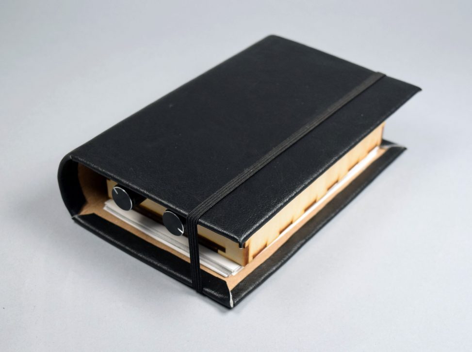
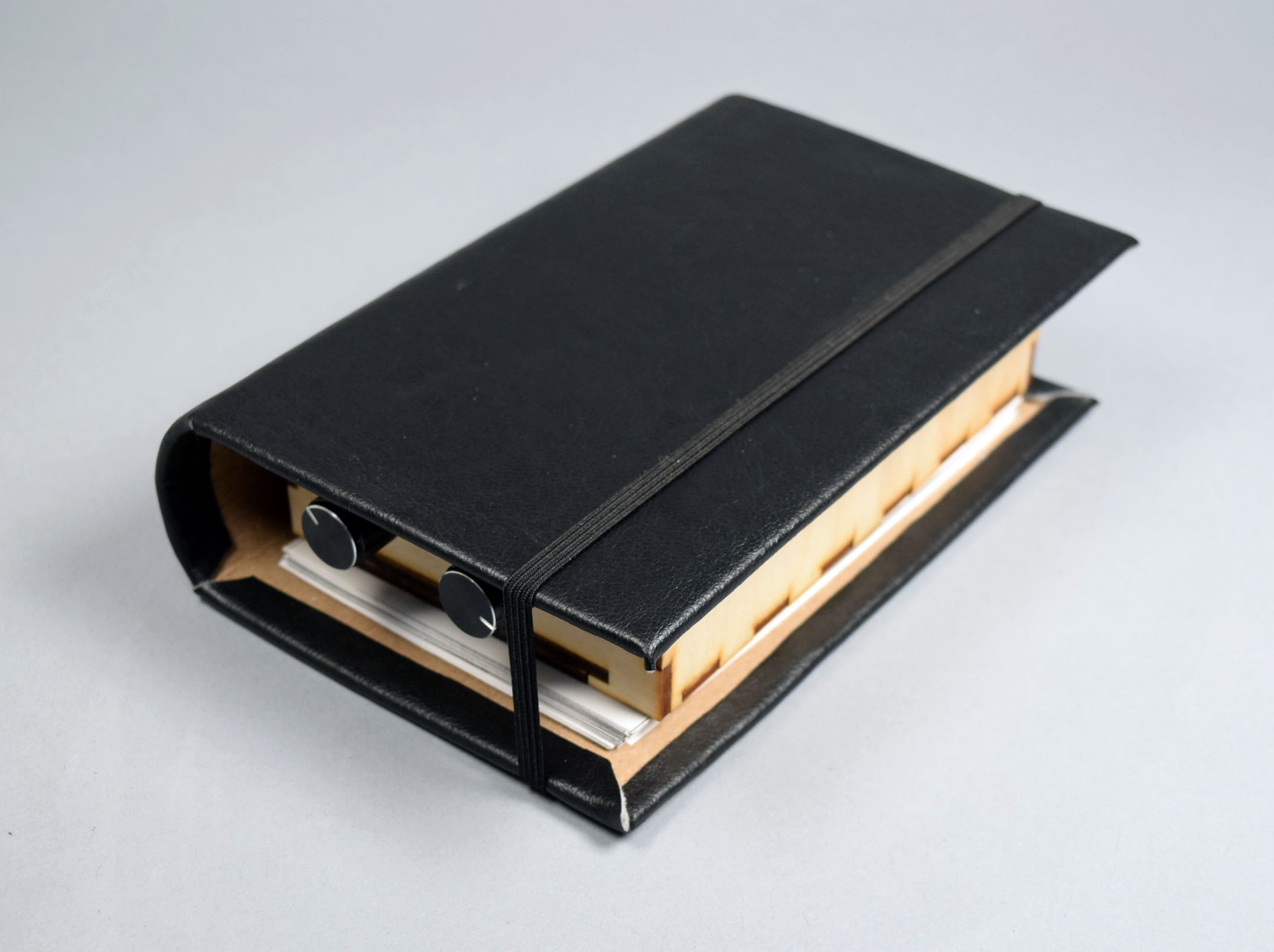
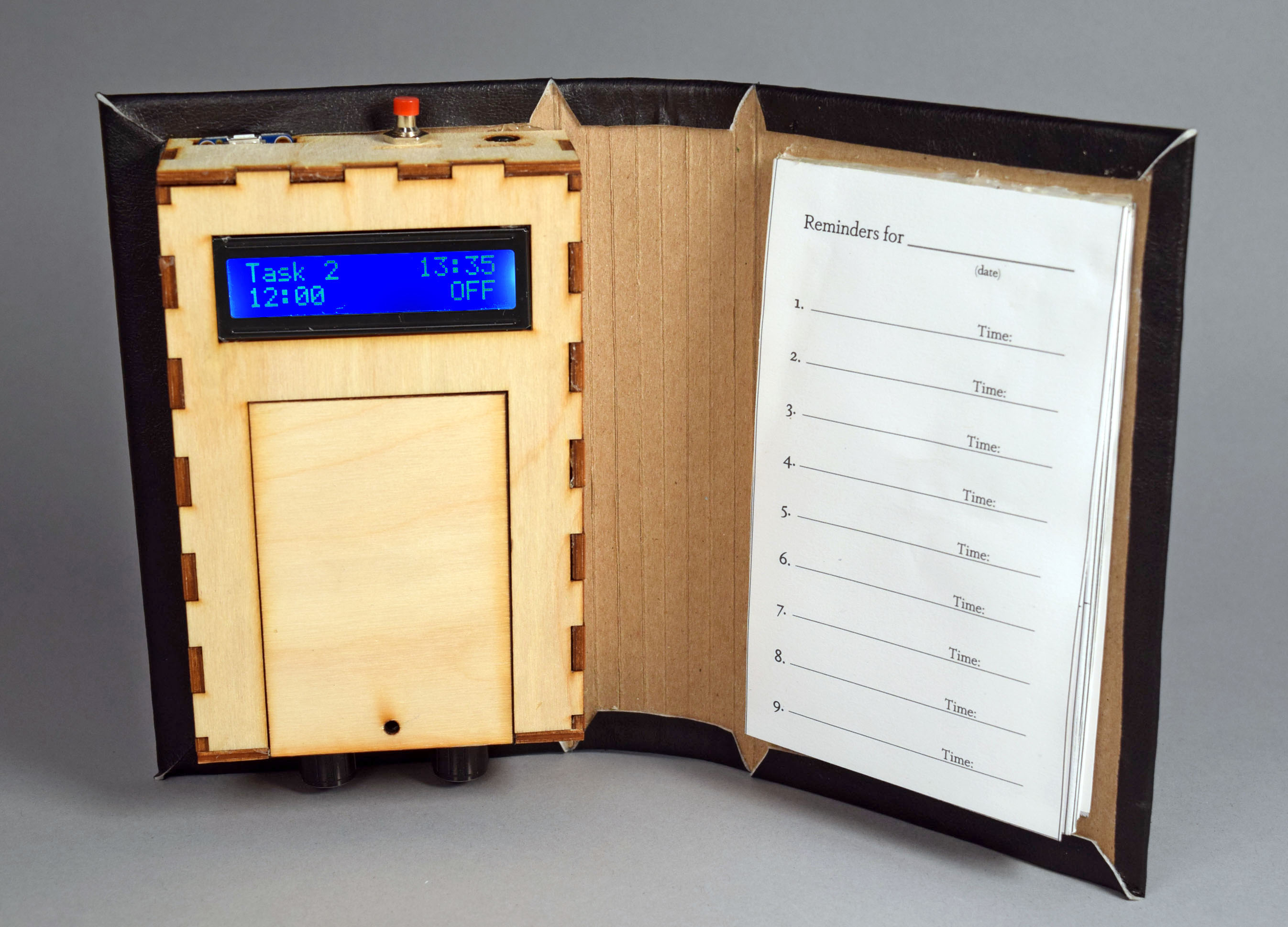
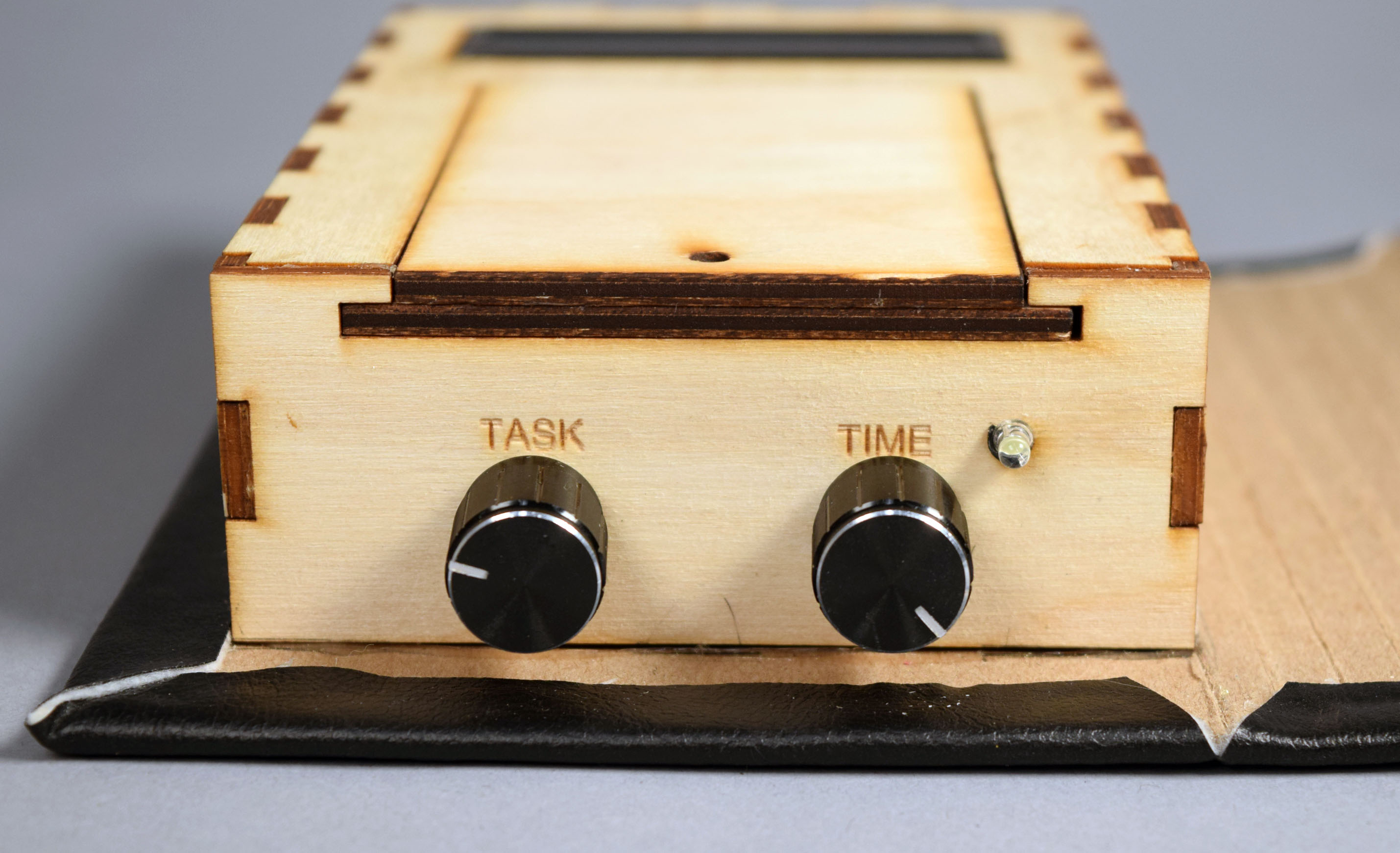
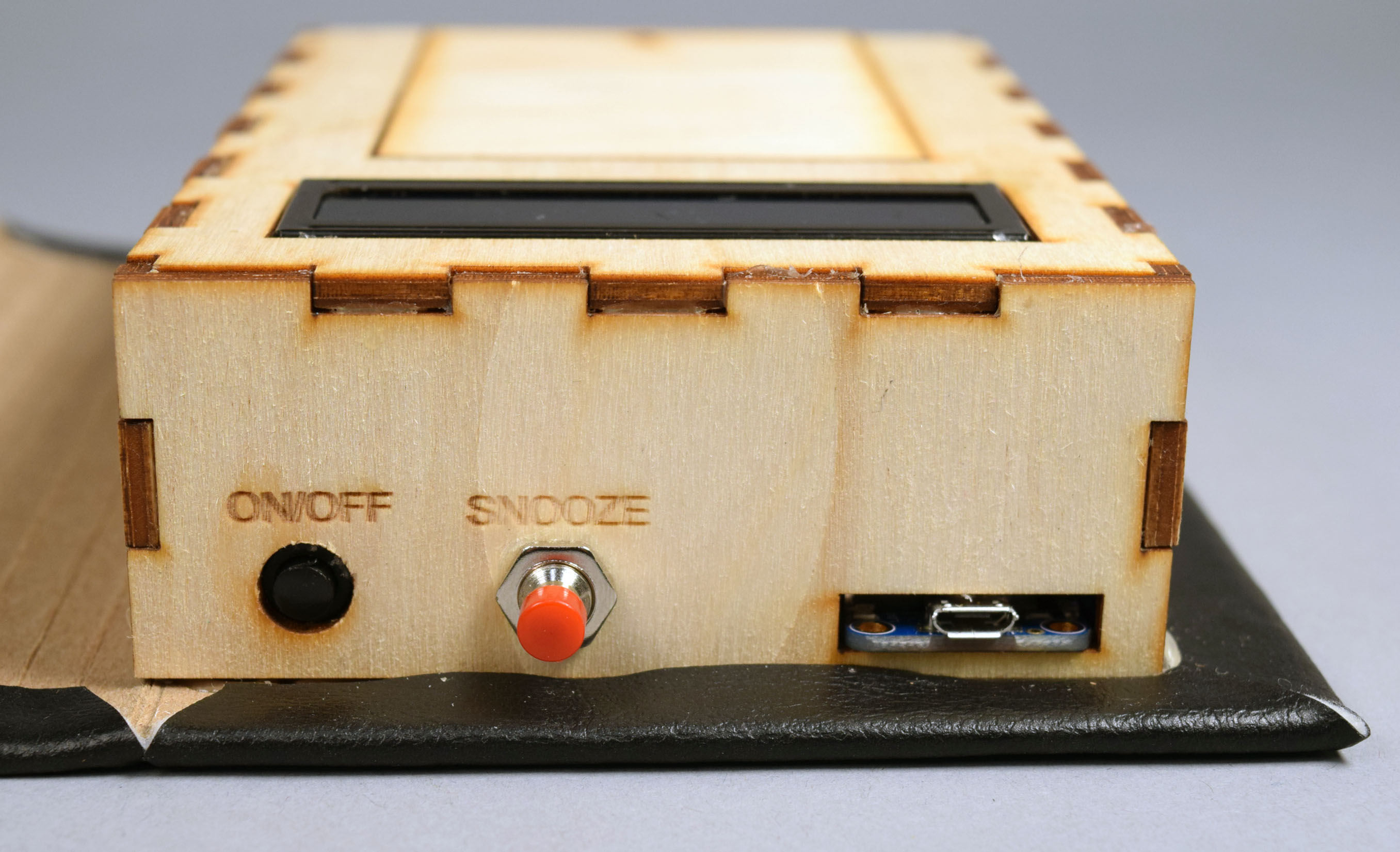
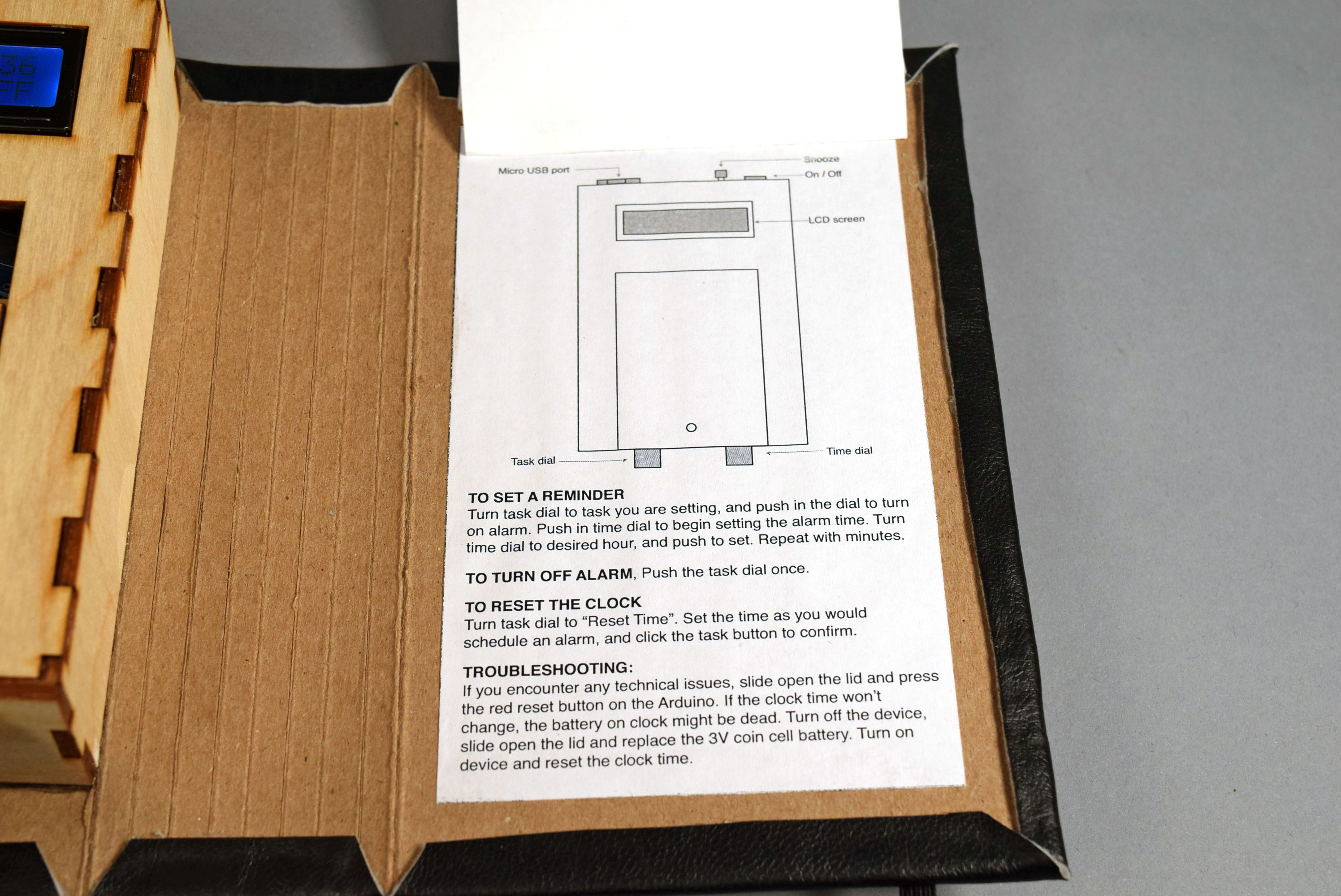
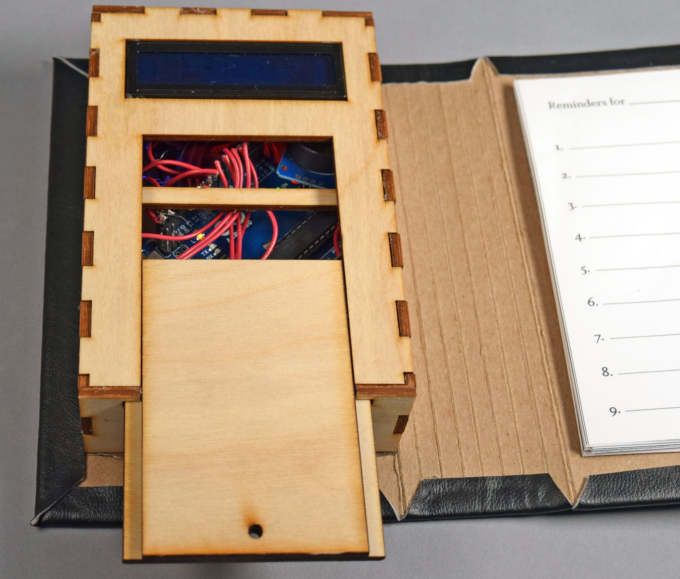
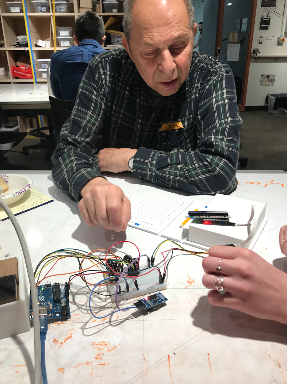
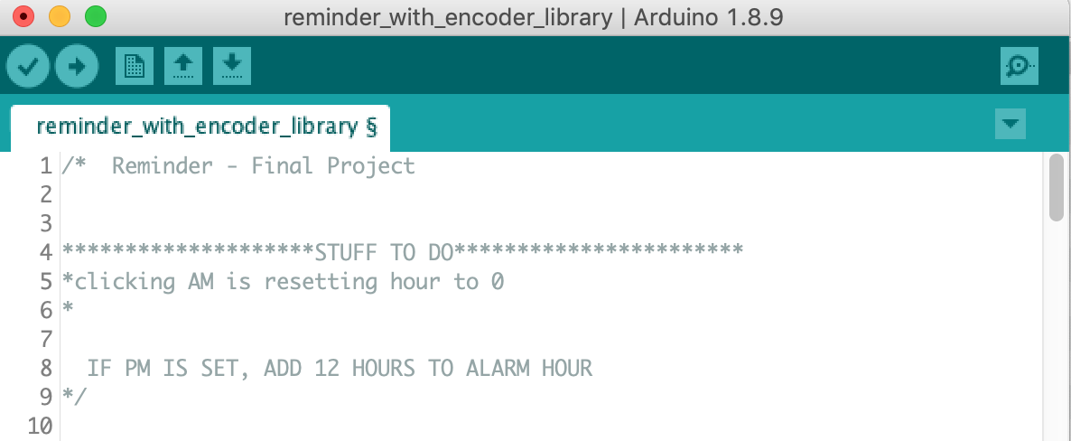
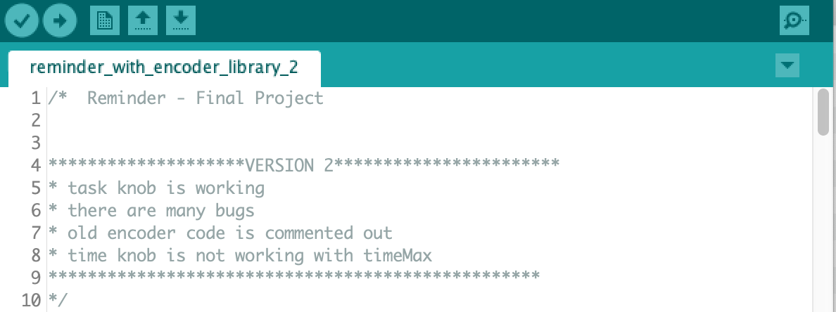
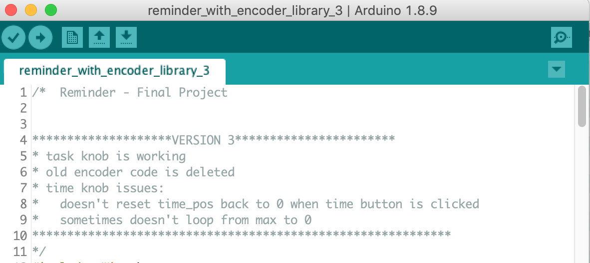
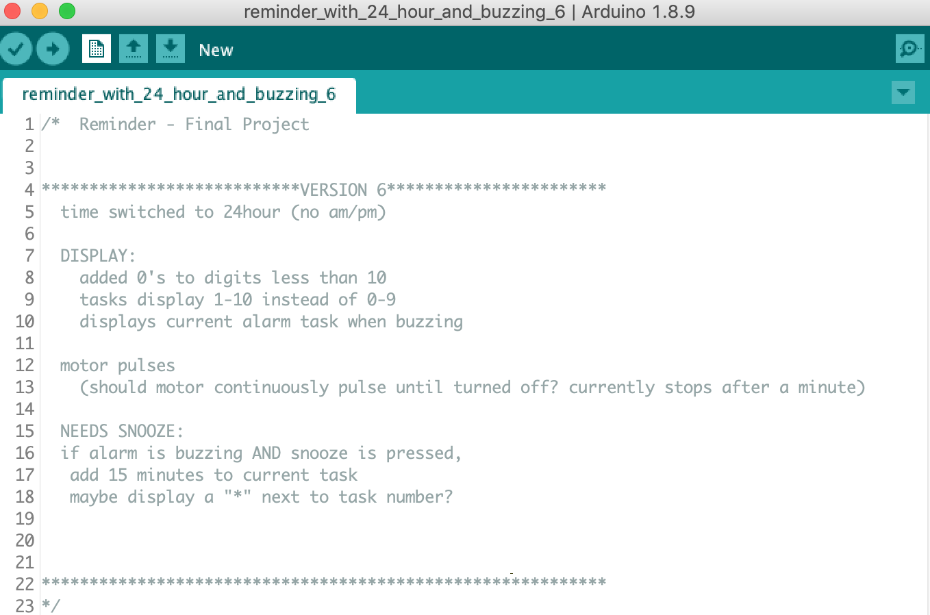
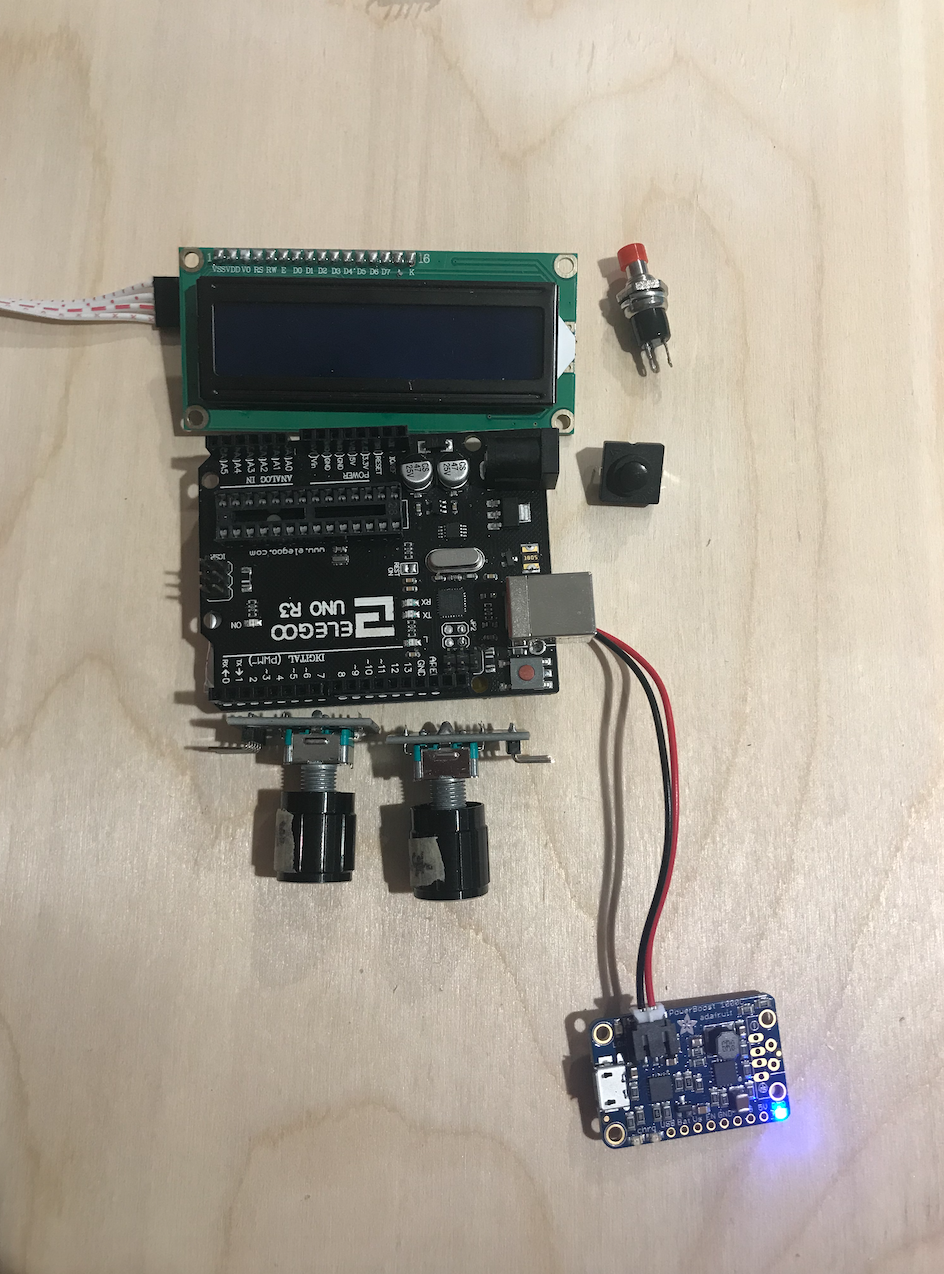
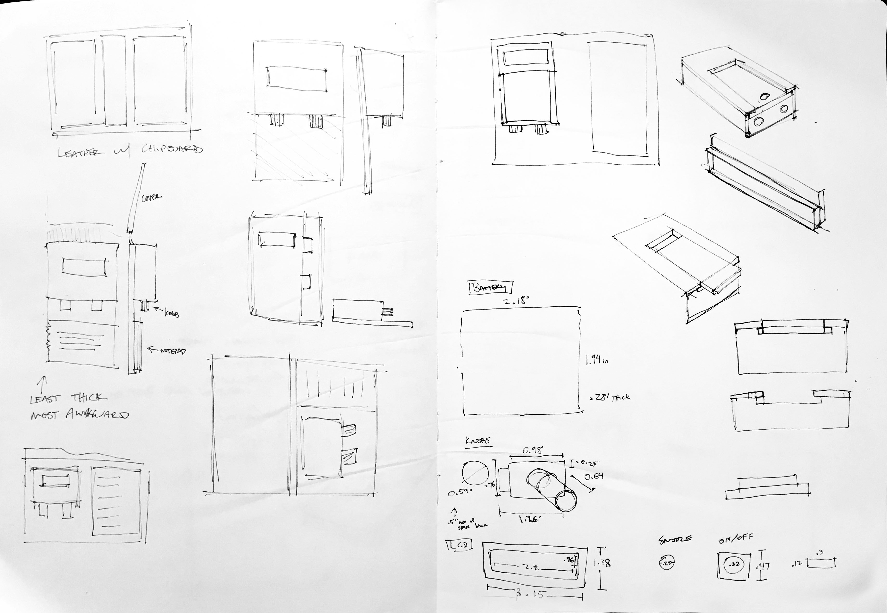
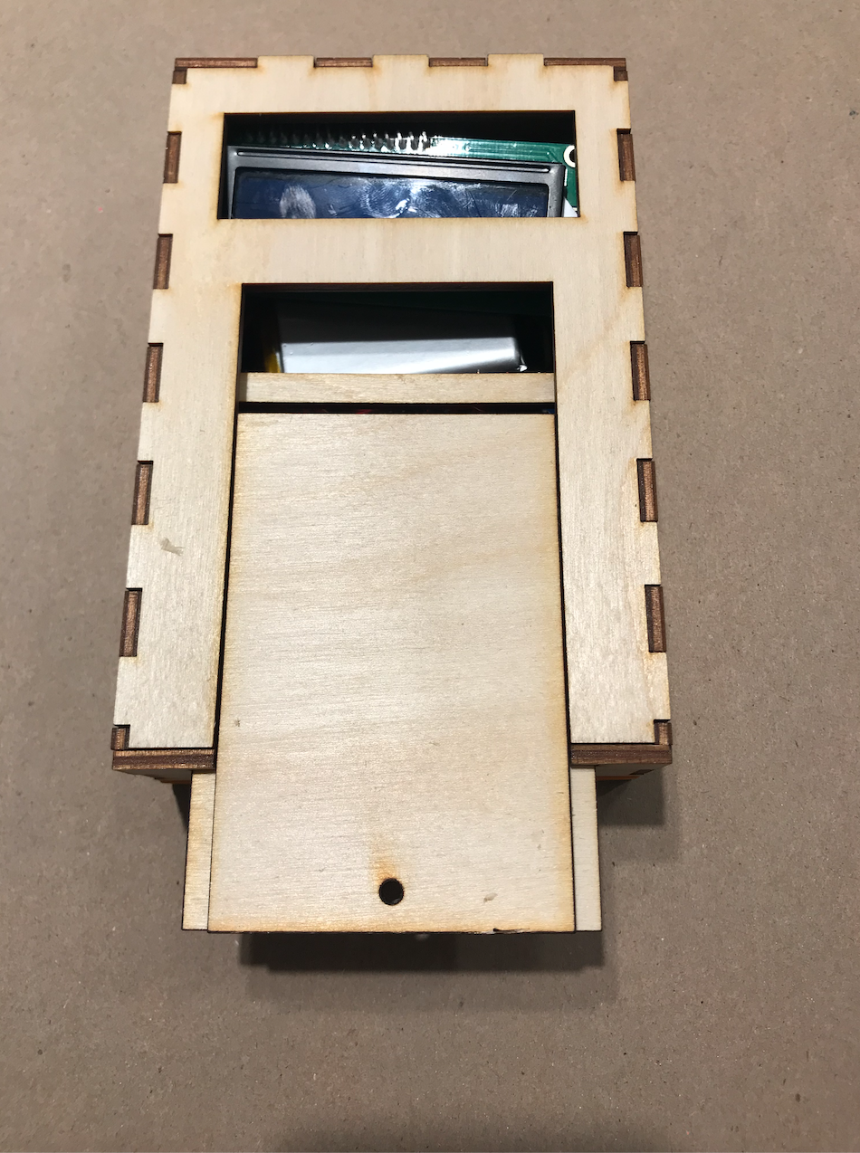
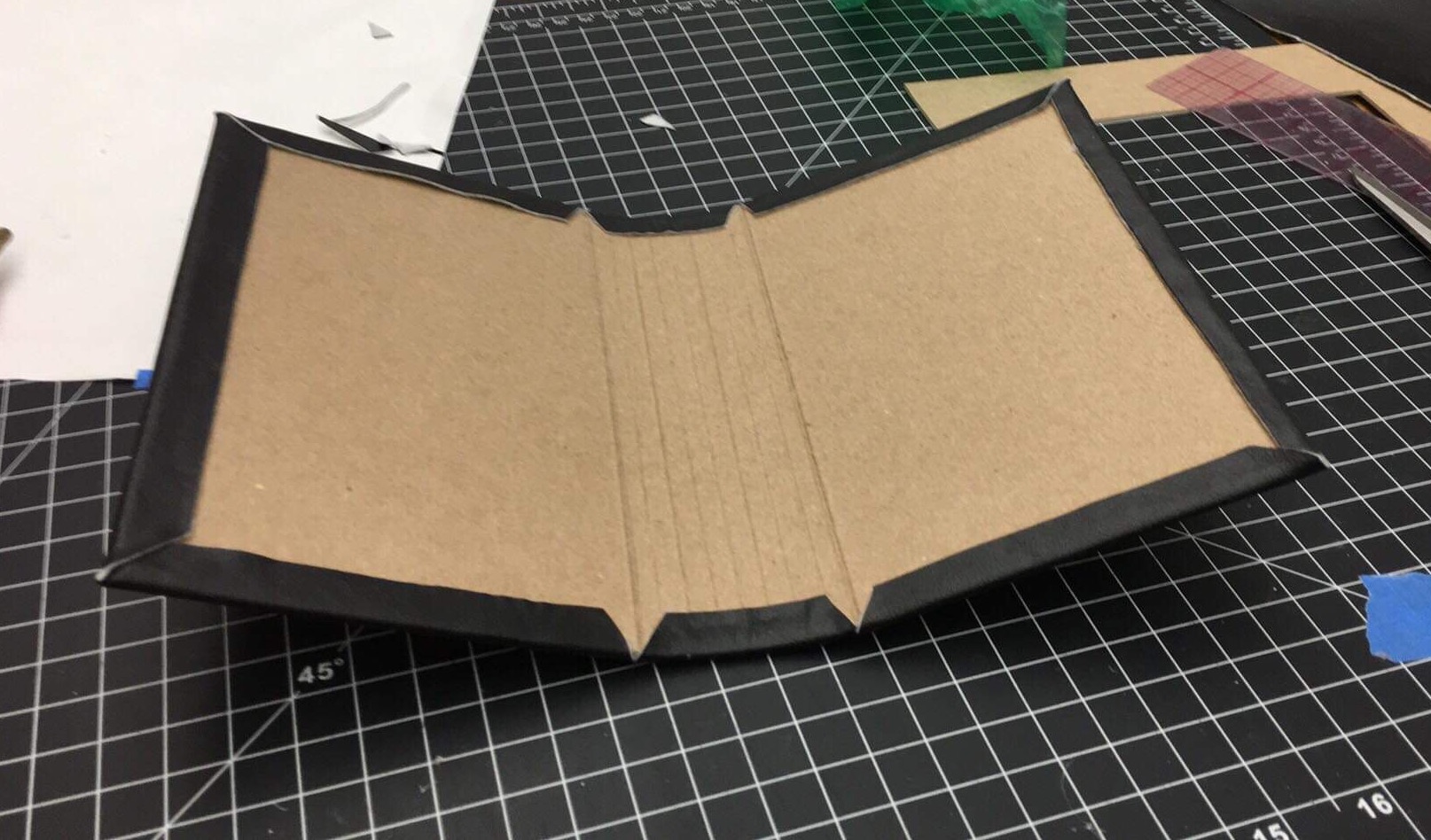
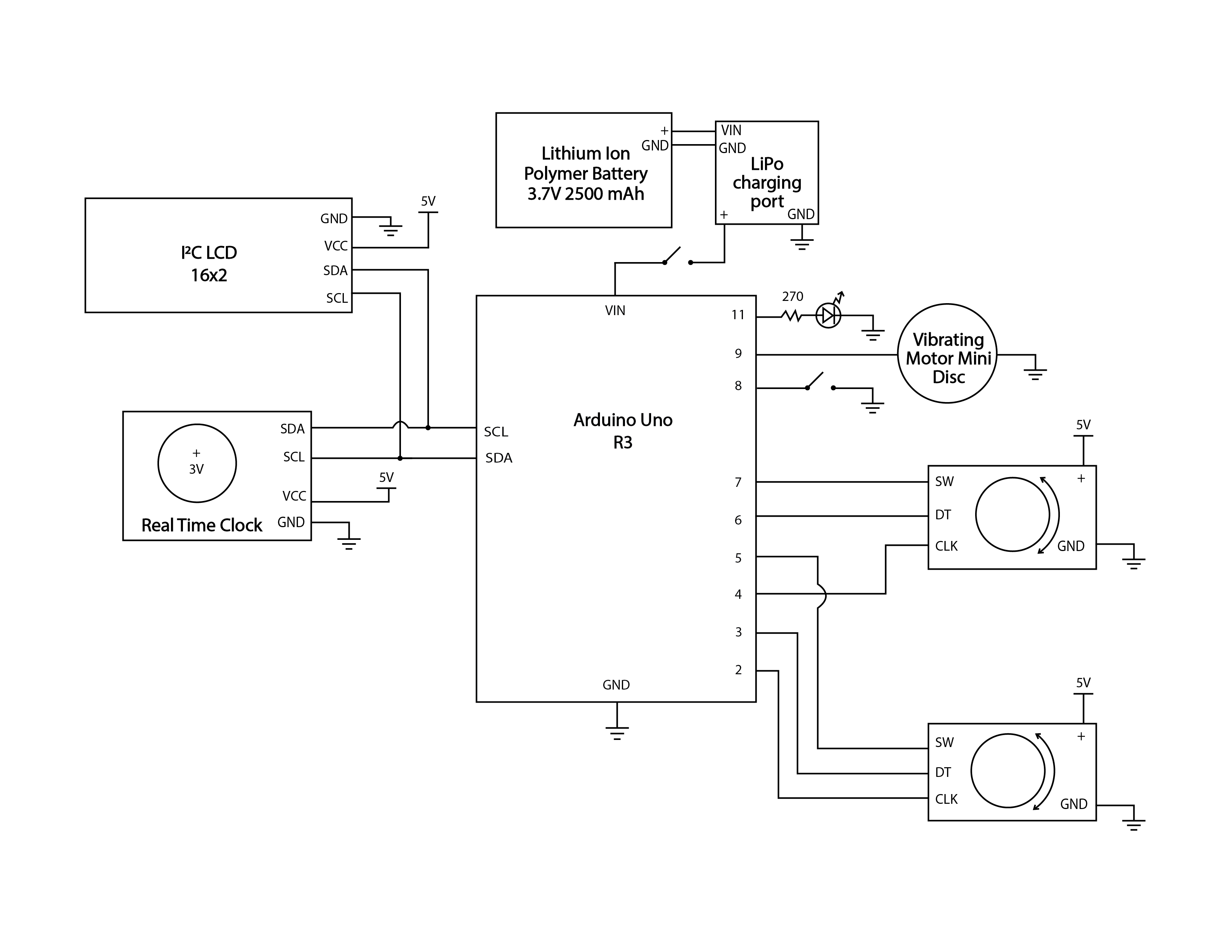
Comments are closed.