Overview
This project features an alarm clock that can only be disabled by pressing a button located across the room from the users sleeping location.
Device Overview
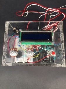
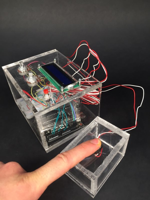
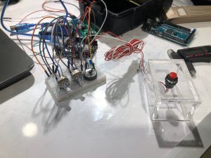
User interface consisting of an I2C LCD display, 2 potentiometers, and a push button.
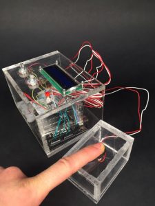
User turning off alarm using the deactivation button.
Process Images and Review
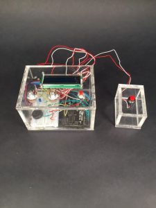
As a mechanical engineer, I have developed a fascination with the working world around me. I like to see how things work and how they differ from other objects and products similar to them. This prompted me to construct my final iteration using clear acrylic to house the electronic components of my alarm clock.
I originally intended to use an LED light strip mounted above the users bed as another method of notifying the user to wake up. I decided against this due to the extra power required and increase in the wiring needed to be installed in order to have the lights mounted externally.
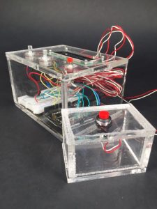
Clear acrylic allows user to see the inner workings of the clock and also makes it easier to see the LED when alarm is triggered.
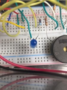
LED mounted inside the device decreases the amount of external wiring required and also illuminates and emphasizes the electrical components of it.
-
Clear acrylic allows user to see the inner workings of the clock and also makes it easier to see LED when alarm is triggered.
Discussion
I received a lot of valuable feedback during the in-class critique. One of the responses recommended the following: “It would be cool if a bluetooth module was added to connect the two parts instead of string.” This idea crossed my mind as well. I ultimately decided not to include a bluetooth. In an attempt to make the device more power efficient, I decided against using methods involving extra power and/or a constant need for power. This is also the reason I decided against using an LED strip and including a continuously running clock. Other feedback that I received stated “maybe add a different power source which would make it more long term.” I could not agree with this more. The end goal of the project was to include a power supply that could be plugged into a wall outlet. I chose to keep the battery as a power source to ensure easy setup and portability during the building and revision process as well as the peer feedback portion of the project.
- Overall I am satisfied with the result of my project. It does everything that I intended for it to do while remaining in line with my goal of reducing overall power needs for the gadget. Although I met my main goals for the project, I found that reducing power led to my project having less of a wow-factor to it. Along with this sort of interesting vs. efficient balance that exists, this project also helped me come to notice some of the patterns that I have developed in terms of my own work flow. It took me some time to figure out how to use the I2C LCD screen that I implemented in my device. I spent countless hours trying to figure this out when I could have spent that time working on other aspects of my project. It has helped me realize the importance of utilizing the resources that are available to me as early and often as possible so that I do not waste as much time working on something that can be accomplished much faster with a little bit of help. This is definitely something I would do if I had the chance to do it all over again. I do not see myself iterating again on this project, but if I were to, I would most likely make the device invoke more of a sense of urgency. By this I mean more lights and more noise. After being placed in the enclosure, the noise became a little quieter than I had intended, and this is definitely something that can be easily fixed.
-
Technical Information
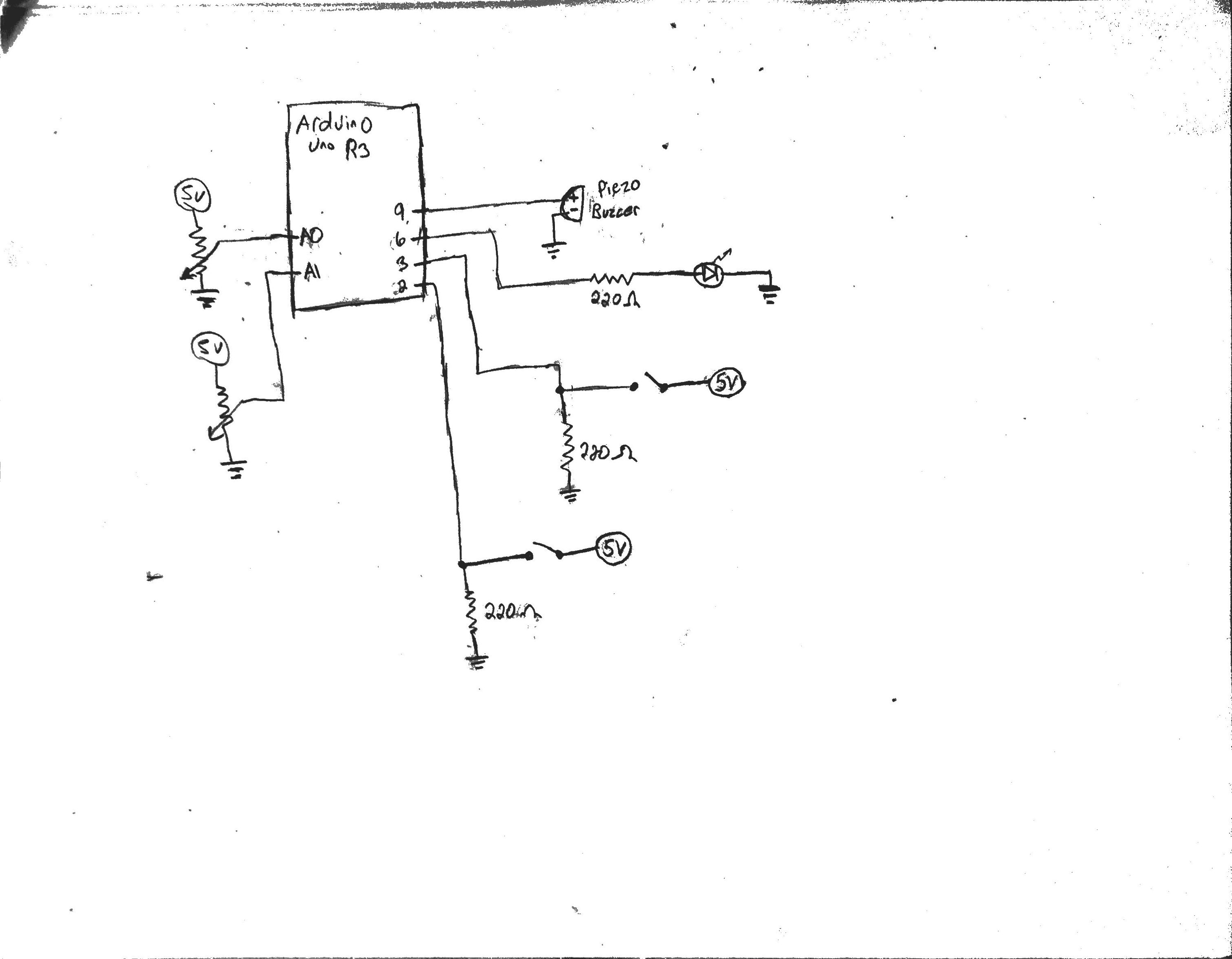
- Wiring Schematic
- Code
-
/*Wake Me Wake Alarm
Justin Belardi

Funtionality:
The following code uses readings from 2 potentiometers to set values for hours and minutes.
Upon the press of the set button, the software sets a timer based on the values from the
potentiometers. When the timer reaches zero, an LED flashes and a buzzer beeps, prompting
the user to wake up. The alarm continues sounding and flahing light until the user presses
the stop button located across the room.

Pin Mapping:
Hour Changer: Pin A0
Minute Changer: Pin A1
Set Time Button: Pin 2
Diasrm Button: Pin 3
LED: Pin 6
Buzzer: Pin 9

Credits:
Intro to Physical Computing Code Byte - Displaying data on an I²C LCD screen
-Used for learning how to implement the I2C LCD Screen.
-Setup Code for initializing Screen was used in final software for project
*/

#include <Wire.h>
#include <LiquidCrystal_I2C.h>

const byte HRPOT = A0;
const byte MINPOT = A1;
const byte SETBUT = 2;
const byte STOPBUT = 3;
const byte LED = 6;
const byte buzzer = 9;

//Initilize variables used to set timer and countdown
int hrRead = 0;
int minRead = 0;
int hours = 0;
int mins = 0;
int timer = 0;
int hrsLeft = 0;
int minLeft = 0;
int secLeft = 0;

//Initializing state variables that are used to tell the software which
  //loop that should be run based on previous code and user input.
volatile byte setState = LOW;
volatile byte stopAlarm = LOW;

LiquidCrystal_I2C screen(0x27, 16, 2);


void setup(){
  pinMode(HRPOT, INPUT);
  pinMode(MINPOT, INPUT);
  pinMode(SETBUT, INPUT_PULLUP);
  attachInterrupt(digitalPinToInterrupt(SETBUT), start, RISING);
  pinMode(STOPBUT, INPUT_PULLUP);
  attachInterrupt(digitalPinToInterrupt(STOPBUT), alarmOff, RISING);
  pinMode(LED,OUTPUT);
  Serial.begin(9600);

  screen.init();
  screen.backlight();
  screen.clear();
}

void loop(){
  if (setState == LOW){ //If the set button has not been pressed yet...
    screen.home();
    screen.print(" Set Sleep Time ");
    stopAlarm = LOW;
    hrRead = analogRead(HRPOT);
    minRead = analogRead(MINPOT);
    hours = map(hrRead,0,1023,0,24);
    mins = map(minRead,0,1023,0,60);
    screen.setCursor(0, 1);
    screen.print((String) "Hrs: " + hours + "  Min: " + mins +"  ");
    timer = hours*3600 + mins;
    Serial.println((String) "Hours: " + hours + " Minutes: " + mins);
  }
  else{
    //simulates a timer by looping until a value of zero is reahed
      //while reducing time value by 1 and delaying 1000 ms (1 second)
    while (timer > 0){
      timer = timer - 1;
      Serial.println(timer);
      delay(1000);
      screen.home();
      screen.print("  Sweet Dreams  ");
      screen.setCursor(0, 1);
      screen.print("...zzzzzzzzzz...");

    }
    while (stopAlarm == LOW)
    //after the timer reaches zero, this block of code runs until
      //the user interrupts the signal by pressing the stop button
    {
      screen.home();
      screen.print("TIME TO WAKE UP!");
      screen.setCursor(0, 1);
      screen.print("Press Big Button");
      digitalWrite(LED,HIGH);
      tone(buzzer,1000);
      delay(500);
      digitalWrite(LED,LOW);
      noTone(buzzer);
      delay(500);
      setState = LOW;
    }
  }
}


//following 2 loops change the value of the state values on the
  //activiation of the interrupt buttons
void start(){
  setState =! setState;
}

void alarmOff(){
  stopAlarm =! stopAlarm;
}
Comments are closed.