This device lets you turn a dial to set an allotted time and get a qualitative light display showing you how much of that time has passed as a way to help accomplish short tasks while remaining focused.
Here is a video showing it in action. Unfortunately, my video was (way) too large to embed, even as an .mp4.
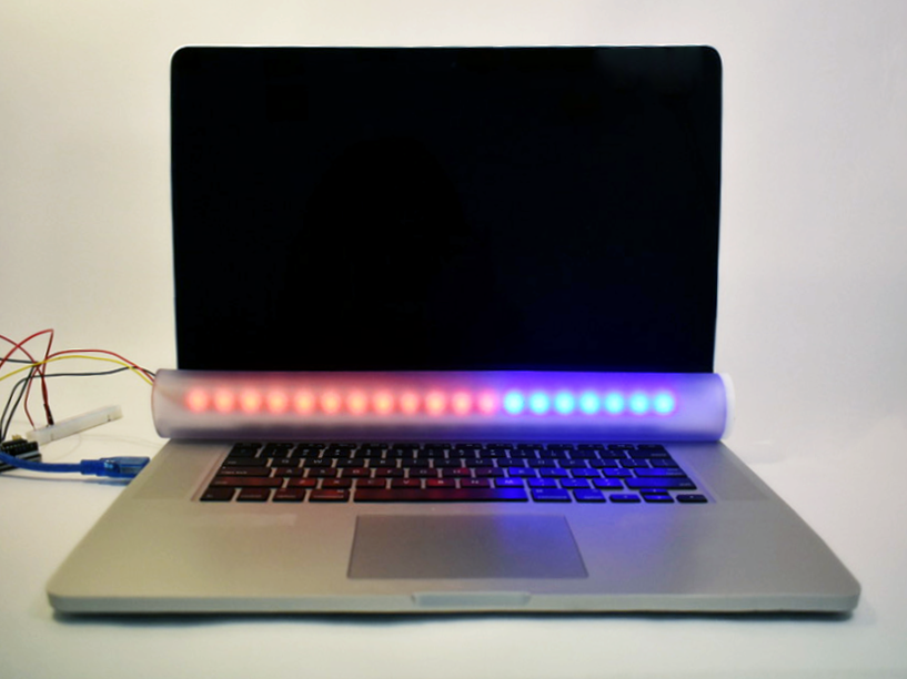
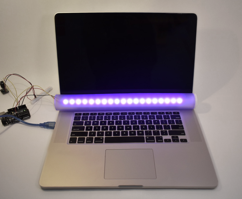
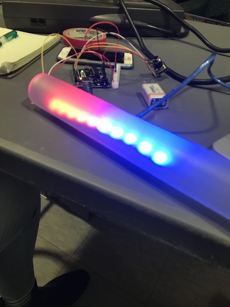
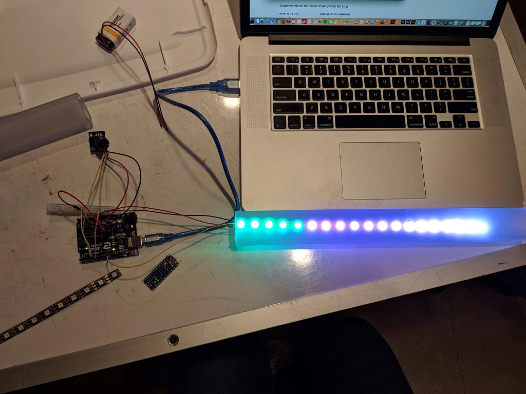
Device in action, time is almost half up
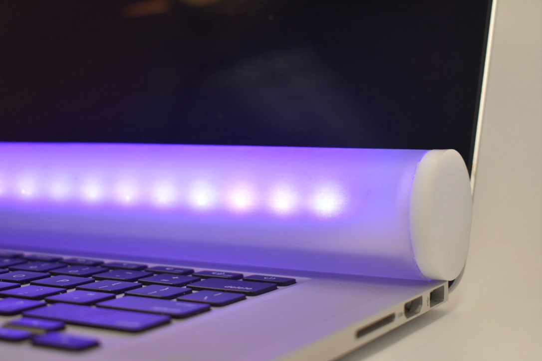
Close up of the end of the device, where it is capped with acrylic.
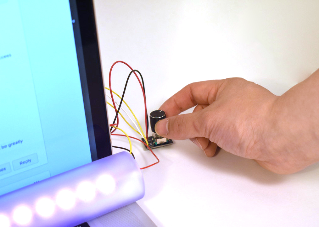
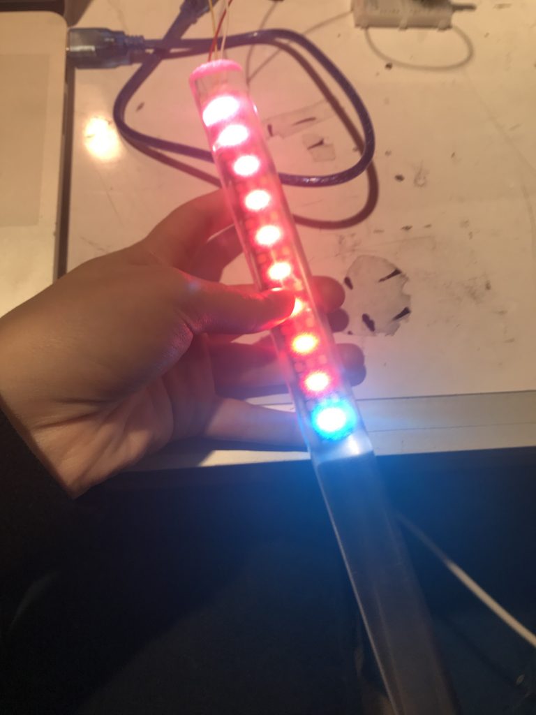
Close up of a hand turning the dial to set the amount of time.
PROCESS:
DECISION 1: DIFFUSING THE LIGHT
Initally I used a rounded piece of acrylic to test how the light diffusion would look
When I was first sketching out the idea for my timer, I was thinking about the design in a lot of detail. I was considering it either being in a frosted box that sat on the table next to you, or sticking directly to your laptop above your screen. When I started working with the LED strip, I decided that because it was thin it would work well attached to, or somehow on, my computer. However, the component wasn’t super attractive by itself and the lights were very bright spots even when I lowered their brightness values, so I decided to incorporate something to diffuse the lights into my design. I started with a piece of rounded acrylic that was sort of sand blasted, and planned to move to a fully sandblasted acrylic tube. I ended up substituting vinyl for acrylic and frosting spray for sandblasting, but it worked with my original design intention.
Testing the diffusion of the frosting spray with a shorter LED strip
DECISION 2: CONCEALING CIRCUITRY
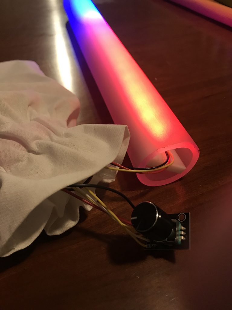
I was unable to fit all my circuitry components into the tube, so I had to keep them in a bag with the rotary encoder sticking out.
My initial intention was to use an Arduino nano and solder everything together so that it and the rest of my components could fit into the tube encasing the LED strip. I initially was working with an Arduino Uno, a normal breadboard, and a shorter LED strip to test the software on before I moved to the final design. However, the night before the project was due I heard multiple people talking in the Phys Comp Lab about how using the Nano had caused serious issues for their project. I decided not to risk any of the device’s functionality over some style points and ended up just putting my components in a bag to hide some of the wiring.
If I had found this out earlier I would have made a slightly less makeshift holding for this, like a laser cut box or something.
ADDITIONAL PROCESS PICTURES:
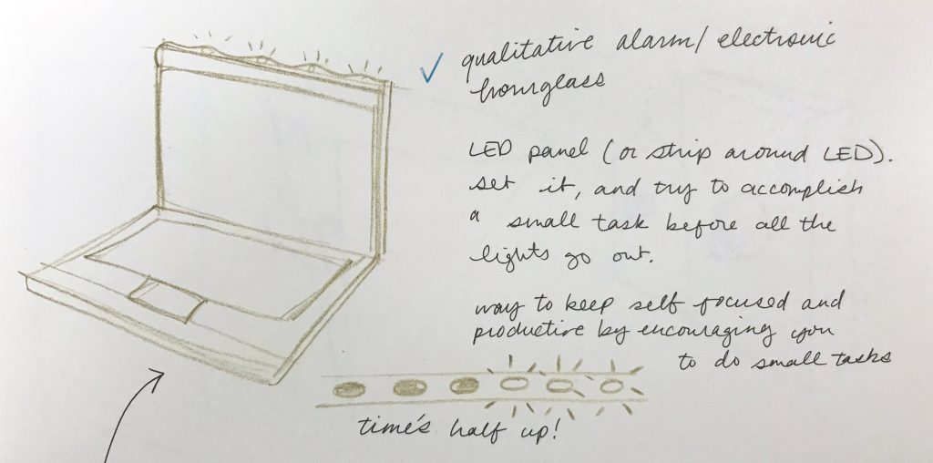
My original sketch for the idea, where I had planned to attach a different type of LED strip to the top of my laptop.
Functional project that hadn’t been fully assembled into its final form yet
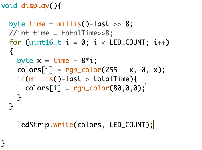
I initially kept trying to make my code work using the same code structure in the example I was working off of, because with some adjustments it was doing something similar to what I wanted it to do. While this example did inform my timer’s resting visual, I ended up changing the structure of the code completely for the main display.
DISCUSSION:
I was fairly happy with how my project turned out. Through the process of making, I had a lot of fun with the container for the device, cutting and frosting the tube, and making the end caps for it. I think it would have been really satisfying to get everything in the tube. I also learned that I really like assembling circuitry and soldering, probably because it’s pretty simple circuitry. I liked how the frosting of the tube and finding the right positioning of the LED strip within the tube diffused the light nicely. I had had some initial trouble with my materials, not being able to find the right acrylic tubing and so having to use vinyl, and then needing to switch to a frosted glass spray as opposed to sandblasting to create the frosted effect was at first stressful, but worked out better than I had expected, although is maybe less durable because the spray can be scratched off.
Although I wasn’t able to get all of my circuitry into the tube for the final crit, which I think would have made the whole thing look more polished, it worked really consistently, which at a certain point the day before, didn’t seem likely. I did struggle with the software for the LED strip. I had a lot going on and so when I tried to write my code it was sometimes hard for me to understand what it was the examples were actually doing, and to simplify it down to something I could use. It ended up just being an if-else statement within a for loop, but getting my mindset away from a more complicated idea took longer than I thought.
A lot of the critique I got in class were things I was wishing I’d been able to do in the first place – for example on person said that “It does seem a bit bigger than preferable, and would be cool to have it in a form in which you can have it stay attached to the computer.” This actually was close to my original intention. While I had intended for it to be in some sort of tube casing, I had hoped to either put a slit in the tube so it could slide over the top of your laptop (and unintentionally solve the “should I put something over my laptop camera in case the FBI is spying on me?” quandary), or create an attachment to the tube that allowed it to hang over the top of your laptop.
Another piece of critique that I got from multiple people was that the rotary encoder should have some sort of feedback like Ian’s project, like “maybe… a click like some previous project to tell you the threshold of the time you are setting with the rotary encoder.” While I feel like sound could have been an interesting enhancement, I don’t think I would have gotten this critique multiple times if people had gotten the chance to turn the rotary encoder themselves because it does have feedback built in, you can feel it clicking, unlike with Ian’s project, where because you weren’t interacting directly with the rotary encoder, you lost that feedback from the part itself.
For the next iteration I am hoping to change the resting state to a more calm, pulsing gradient to be less distracting, to 3D print a bigger cap for the dial of the rotary encoder so it’s more comfortable to turn and you’re more likely to turn it less than you would be using the original cap, and figure out a way to get all of my circuitry components into the tube. I want to at least try using the Arduino Nano to see if it’s possible to get it to work, otherwise, I will look for other options, like creating a container for all the circuitry components that rests on your desk next to your laptop.
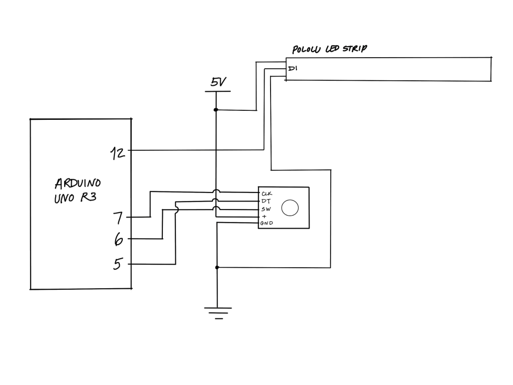
SCHEMATIC:
CODE:
/*
 * Assistive Device: Qualitative Timer
 *
 * Takes input from rotary encoder and translates it to a period of time
 * Then when the rotary encoder switch is pushed,
 * Uses a Pololu LED strip to visualize how much time has passed.
 *
 * Rotary encoder switch pin is connected to digital pin 6
 * Rotary encoder x and y pins are connected to digital pins 5 and 7
 * The digital read on the Pololu LED strip is connected to digital pin 12
 *
 * Code for rotary encoder based off of Paul Stoffregen's Encoder Library Example "Basic".
 * Code for gradient resting state based off of the Pololu LED strip Library example "LEDStripGradient"
 *
 */

#include <Encoder.h>
#include <PololuLedStrip.h>

//rotary encoder object connected to pins 5, 7
Encoder myEnc(5, 7);

//Pololu LED strip object connected to pin 12
PololuLedStrip<12> ledStrip;

const int SWITCHPIN = 6;
int totalTime;
int interval = 0;
bool run = false;
bool done = false;
long last;

#define LED_COUNT 19
rgb_color colors[LED_COUNT];
int count = 10;

void setup() {

  Serial.begin(9600);
  pinMode(SWITCHPIN, INPUT);

}

long oldPosition  = -999;

void loop() {
  //translate rotation of rotary encoder to total timer amount and corresponding interval
  int switchState = digitalRead(SWITCHPIN);
  if(switchState == HIGH){
  long newPosition = myEnc.read();
  if (newPosition != oldPosition) {
    oldPosition = newPosition;
    newPosition = newPosition/2;
    Serial.print("Rotary position: ");
    Serial.println(newPosition);

    //one click forward of the rotary dial adds 1 minute
    totalTime = newPosition * 60000;
    Serial.print("Total time: ");
    Serial.println(totalTime);
    }
  }

//if switch is pushed and the display is not already running, boolean run becomes true
  if(switchState == LOW && run == false){
    //sets timer interval to 1/10th of total time
    Serial.println("SWITCH IS LOW");
    interval = totalTime/LED_COUNT;
    Serial.print("INTERVAL IS ");
    Serial.println(interval);
    run = true;
    last = millis();
    Serial.print("last is ");
    Serial.println(last);
  }

  //if the timer has run out and the switch is pushed, return visual to its resting state
  if (done && switchState == LOW) {
    totalTime = 0;
    oldPosition = -999;
    delay(1000);
    run = false;
    done = false;
  }

//if the switch has been pressed so run is true, show the timer display
//otherwise, go to the resting state visual, a pulsing gradient

  if(run){
    display();
    //Serial.println(last);
  }

  else {
      byte time = millis() >> 4;
  for (uint16_t i = 0; i < LED_COUNT; i++)
  {
    byte x = time/2;
    colors[i] = rgb_color(x,0, x);
  }

  // Write the colors to the LED strip.
  ledStrip.write(colors, LED_COUNT);

  delay(10);
  }

}

void display(){

  for (uint16_t i = 0; i < LED_COUNT; i++)
  {
    //if amount of time past since the timer was set is greater than the totaltime/10 *(i+1)
    //LED is red, otherwise LED is blue
    if (millis()-last > interval * (i+1))
      colors[i] = rgb_color(80,0,0);
    else
      colors[i] = rgb_color(0,0,80);
    }

    ledStrip.write(colors, LED_COUNT);

    if (millis() - last > totalTime)
      done = true;
}
Comments are closed.