INTRODUCTION
As a team, we (Carlos Ortega and Amelia Lopez) worked with Annie Verchick to develop a gadget suited for her unique needs. Checking mail was always a challenge for Annie, and at one point she had six weeks worth of mail piled up. Included in that mail was time-sensitive information and money which she missed due to not checking the mail on time. Clearly, this was a problem for her that desperately needed a solution.
We ended up designing a simple, elegant device so that Annie could see at a glance if she received mail in her mailbox without having to go outside. From inside her house, she could check the lights on a wall mounted box or read from an LCD display also on the box which displayed either “you’ve got mail” or “no mail.” Further on in the documentation we discuss the specifics of the design. For previous designs/problems we considered solving for Annie, please see our interview documentation linked here where we spend time explaining why we settled on solving this problem for Annie and what our initial sketches looked like.
WHAT WE BUILT
Our device, “You’ve Got Mail”, checks if there is mail in our client’s mailbox. It does this through 2 or 3 sensors we place strategically inside the mailbox Annie has mounted to her wall outside. These sensors tell us if there is something inside the mailbox. Inside her house we’ve built another box which has two lights (1 green and 1 red) and a screen display. If there’s mail, the screen display changes to say “you’ve got mail” or “no mail” if there is no mail. The light turns green when there’s mail or stays red when there is no mail. The box inside is powered through a wall outlet so the display and lights are always on.
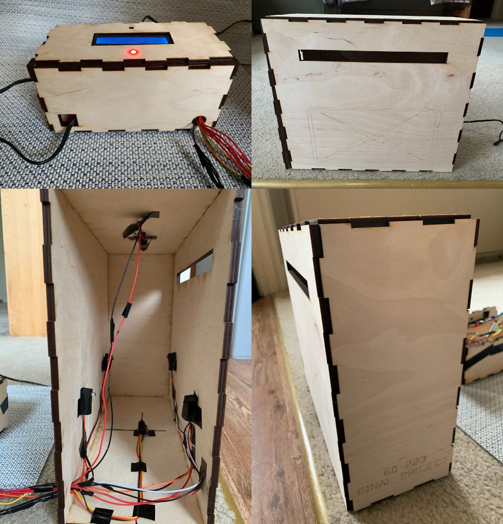
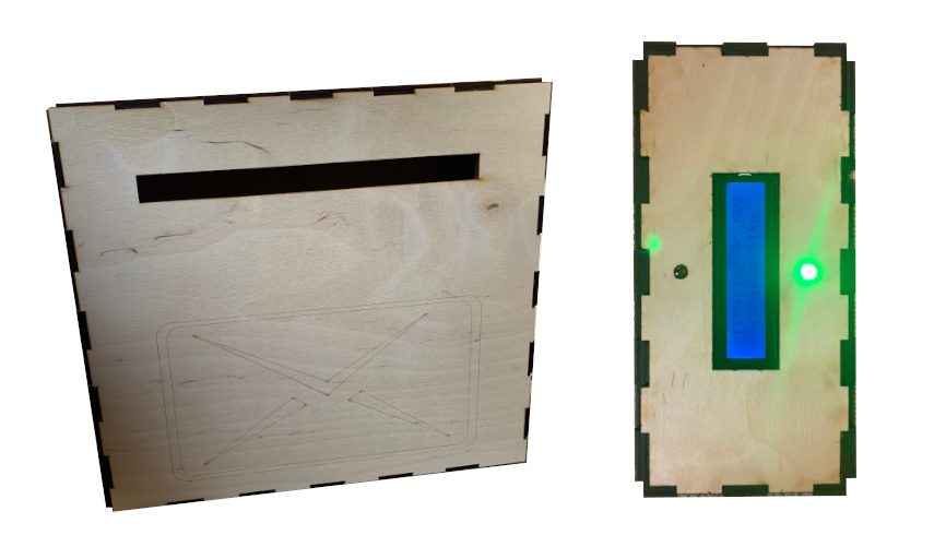
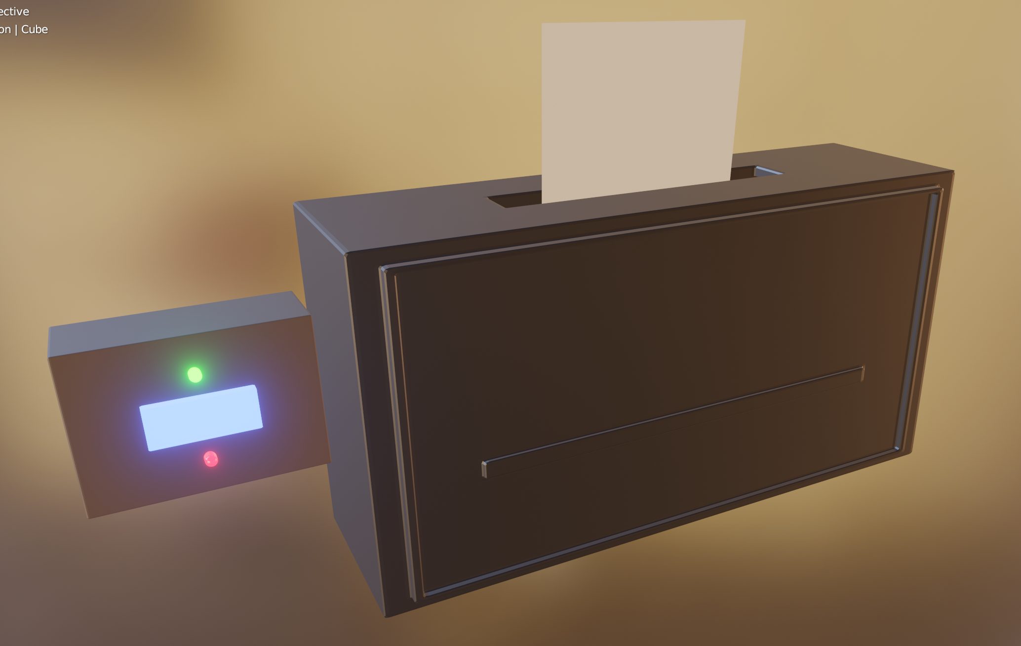
Images of final device. The upper left is the mini-box that would go inside the house; the remaining images are a demo of her mailbox with the sensors inside. The lower left shows what’s inside the mail box (3 sets of break-beam sensors positioned across from each other: top-bottom, left- right, and left-right). The lower right shows a an isometric view of of the box with an engraving, and the upper right picture shows a front view of the mailbox with an envelope engraving and a slit for the mail to go through
Video of the final product:
Narrative Sketch
It’s a cloudy, but bright-feeling day in the Sierra. The snow covers the seldom-used front porch and the wall-mounted mailbox next to the wooden door, which has also been touched by the snow. Meanwhile, Annie and her dog grab the leash and take their time out the side door for an exciting morning in the snow.
Just as they leave, the mailman has been on the opposite side of the house, stuffing the mailbox with the long-awaited family letters and packages. At last, when Annie and her dog return through the old side door, the green light on Annie’s front wall catches her eye. She reads on the newly-installed screen the words “Mail status: You’ve got mail!”
As she eagerly opens the door to open her letters, she sees the mailman on his way back, and they exchange a sweet good morning.
HOW WE GOT HERE (PROTOTYPES AND PROCESS)
Prototype 1: Carlos Ortega
How can we activate the mail checker on command, and from any distance? This prototype uses a wireless remote and an infrared receiver; the mission was to learn how to program them.
How it works: pressing any button on the remote turns (both) lights on. They automatically turn off after 5 seconds. The user can turn the lights off sooner than 5 seconds with the power button on the remote. The final product would decide which single light to turn on (instead of both), but that would come later.
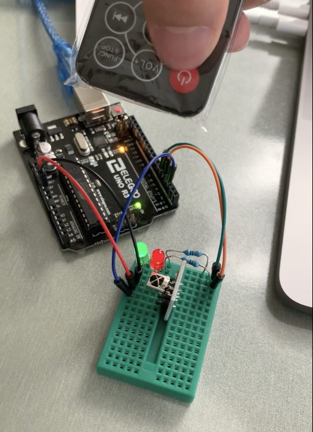
In action: the remote turns the lights on and off.
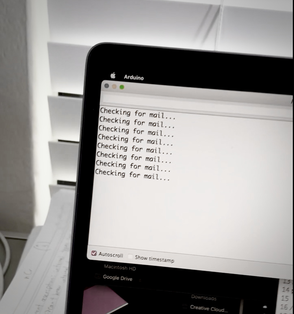
Circuit reports back at every remote control click.
Close-up of the circuit.
Prototype 1 in action
(GIF of prototype 1 in action. WordPress may fail to display…)
Intermediate steps
Left: programming the remote and remote receiver. Right: turning on lights
The lights wouldn’t stop flashing!
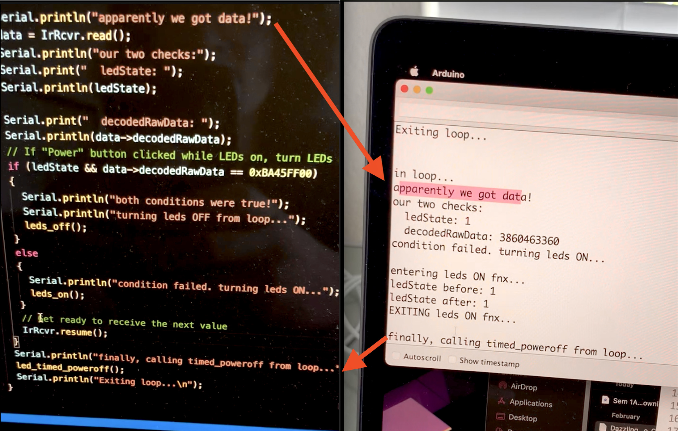
The code reports back which part of the program is currently executing.
The most significant feedback we received: don’t use the remote. The remote came out of our assumption that the mailbox was out in Annie’s yard, far away from her porch, and down a flight of stairs. We were surprised to find out that the mailbox was actually mounted on the wall. Instead, we decided to also mount our gadget on the same wall, on the interior side. The remote, then, would have been overkill, so we decided to scrap that feature.
Based on some feedback, we were also going to add an arcade-style push button for the dog to check the mail with his paw. It was just for fun, but we scrapped that extra feature too before we even started implementing it.
Even so, prototype 1 really did answer the question of how do a remote control and a receiver work? The remote sends pulses of infrared light of different durations. When combining pulses of different lengths, we can recognize those patterns, and encode information; each button press sends out a different pattern. The infrared sensor receiver detects the pulses, sends them to the Arduino, and the Arduino can then extract the information from those pulses.
We had to borrow some pre-existing code (called a library) in order to read these patterns from the remote. It was a surprise to see that the example code on our class website used a previous version of the library, and was therefore outdated. I had to look at the documentation for the newer version.
Process
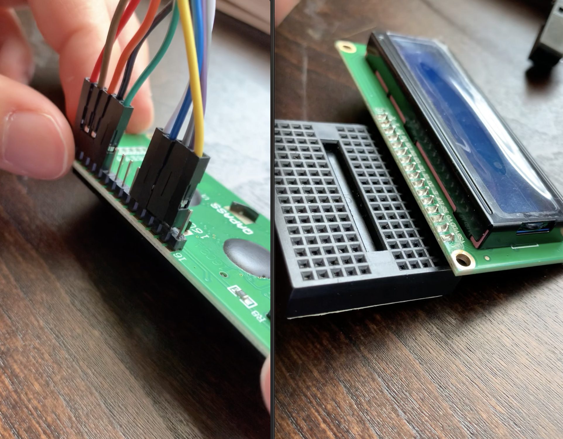
Using a screen for the first time!
Left: not enough cables! Right: plugged straight into a breadboard.
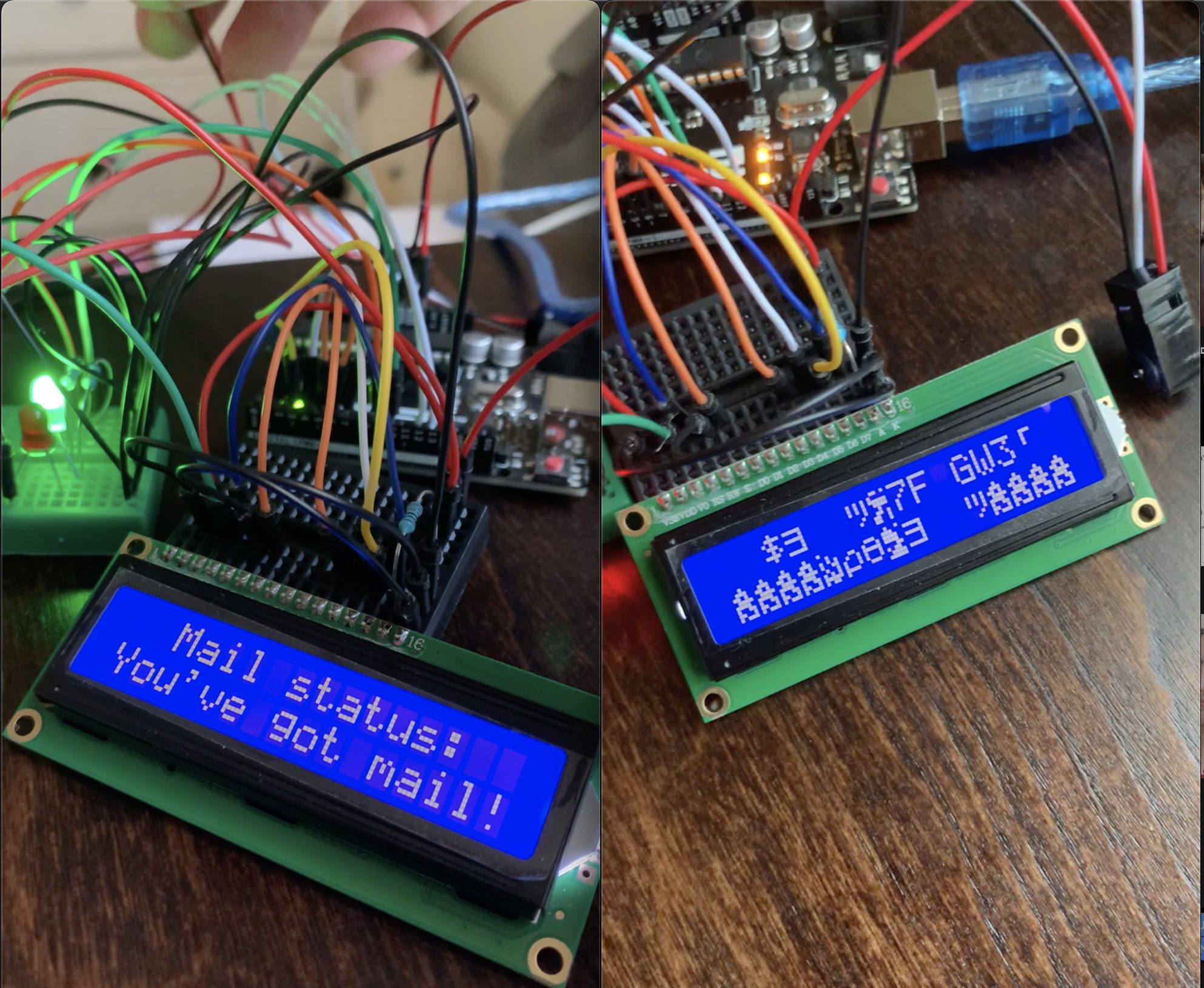
Left: LCD screen working. Right: LCD screen not working.
Mysteriously, the only cause was uploading the code to the Arduino again! With no changes whatsoever to the code! The solution was just turning the Arduino off and back on again.
Designing electrical box in CAD
(Process continued in Amelia’s process section)
Prototype 2: Amelia Lopez
This prototype was designed to help answer the design question: can we use break-beam sensors to ensure mail is accurately detected in the mailbox every time?
To answer this, I designed 2 boxes: one of which served as a representation of Annie’s mailbox where I could put the break-beam sensors, and the second box served as the one which would be inside and had the LCD display as well as 2 LED lights. We were confident the break beam sensor was an ideal device for this project because they work by having an emitter send out a beam of IR light and a receiver receives the light from across. When something interrupts the light, the beam is broken and we know that there is some object in the way, preferably mail.
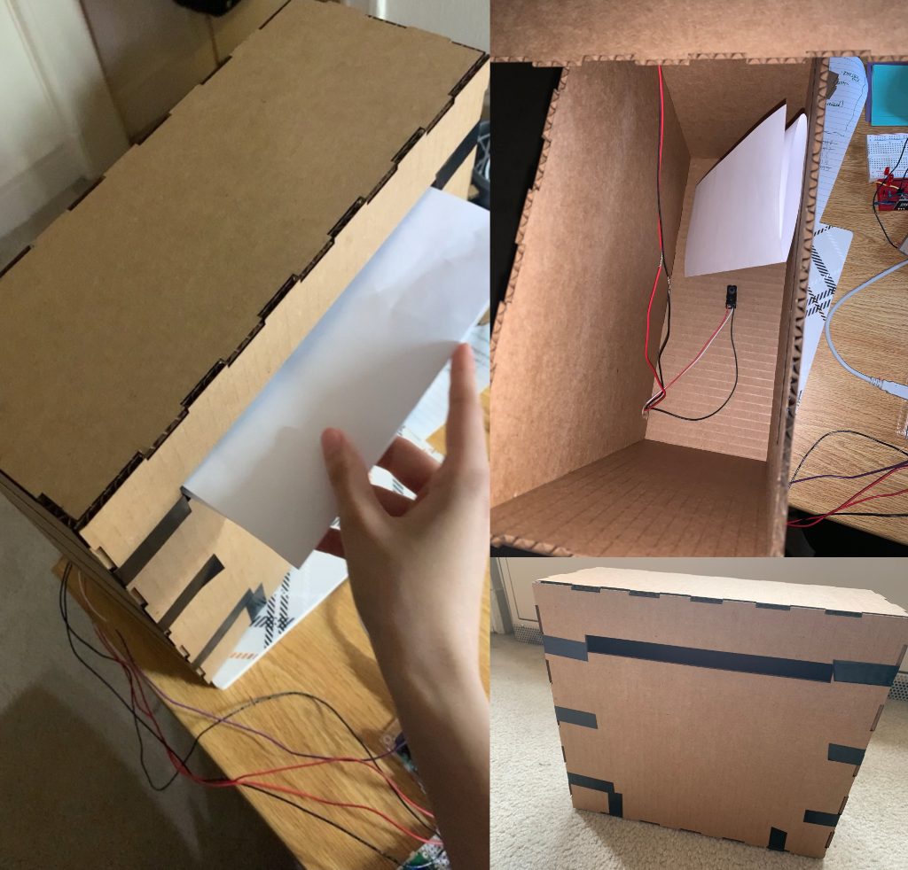
This is my mailbox prototype. I designed the box using AUTOCAD and then laser cut it out of carboard in order to get the design right. The left image shows me testing the output of the sensor by putting in a sheet of paper. The upper right image shows one set of break beams I positioned in the box (top-bottom). The bottom right shows a front view of the box.
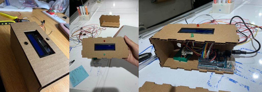
This is my mini-box prototype. The left image shows the box sealed, the center image shows a top view of the box with the LCD screen and LEDs. The right image shows a view inside the box with the Arduino and wires attached.
There are also earlier iterations of my prototype which accomplish the same idea but look more “rough”
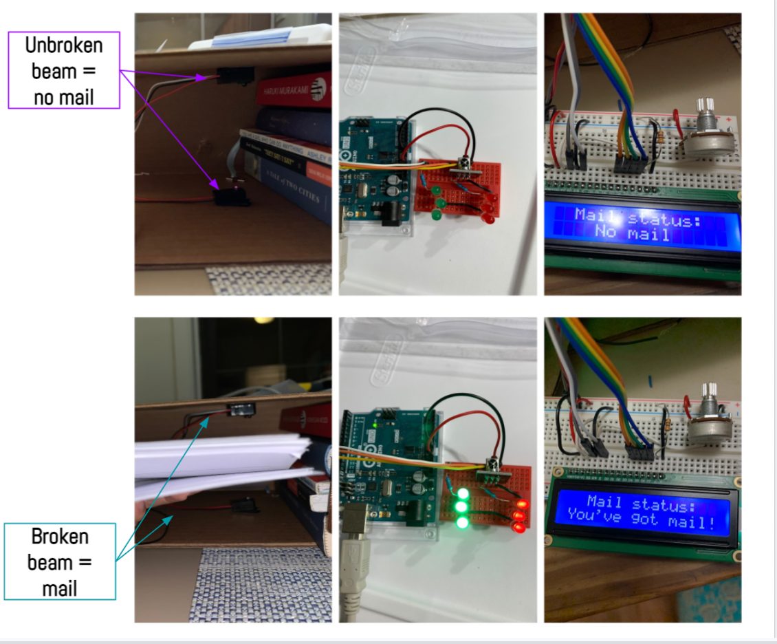
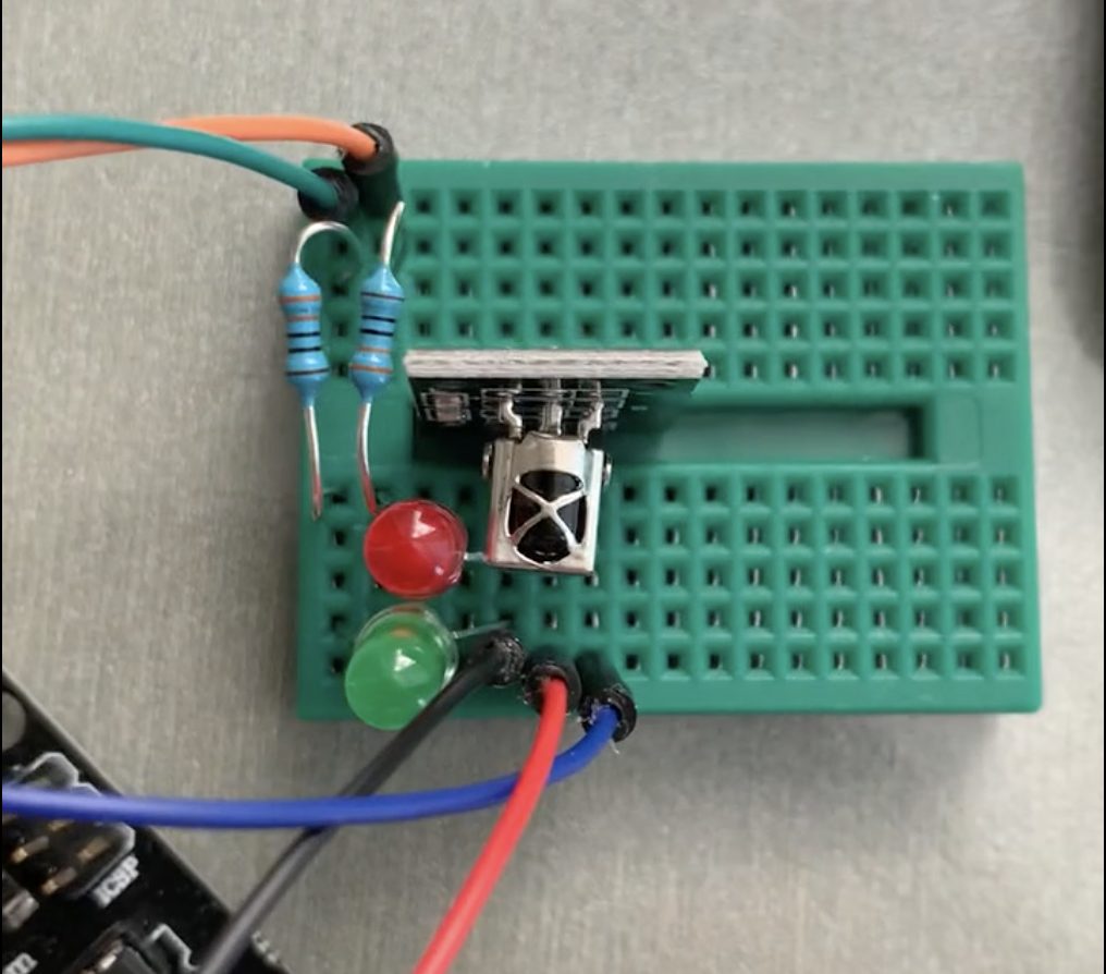
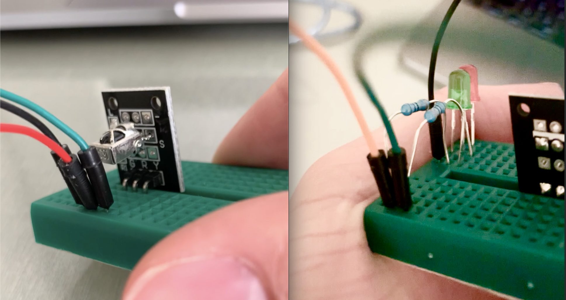
This picture shows an early version of the prototype where I was testing the break beam. The upper 3 images show the LED/LCD status when the break beam is unbroken/ no mail. The bottom 3 images shows the LED/LCD status when the break beam is broken/mail
In my prototyping process, I found that break beams are a great sensor for this particular problem but I needed more than one break beam to ensure the device accurately detected every piece of mail which was surprising. If I positioned the mail too far right or too far left, I discovered that my break beam going from top-bottom didn’t catch that piece of mail. To solve this, I added 2 more sets of break beams (for a total of 3 break beams) both going from left-right but positioned either far left or far right.
Another part of the prototyping process was designing the mini-box that would go inside Annie’s house. We were looking to simplify and clean up the design which meant using a caliper to measure the size of the LCD display and diameter of the LEDs. To mount the LCD, originally we were going to use screws on either corner but found that it took away from the cleanness of the design and settled on using tape on the bottom of the display to hold it together instead so that the front view would only consist of the LEDs and LCD.
In terms of feedback from our client, she was very happy with the design and pushed us to integrate a wall-power adapter instead of batteries in order to power the device. She has many outlets in her home, and this was a simpler solution for her. This ultimately made the design of the mini-box smaller because we didn’t have to worry about storing a battery and caused us to add a square-sized hole to the final design of the box box in order for the adapter to fit through.
Process (continued)
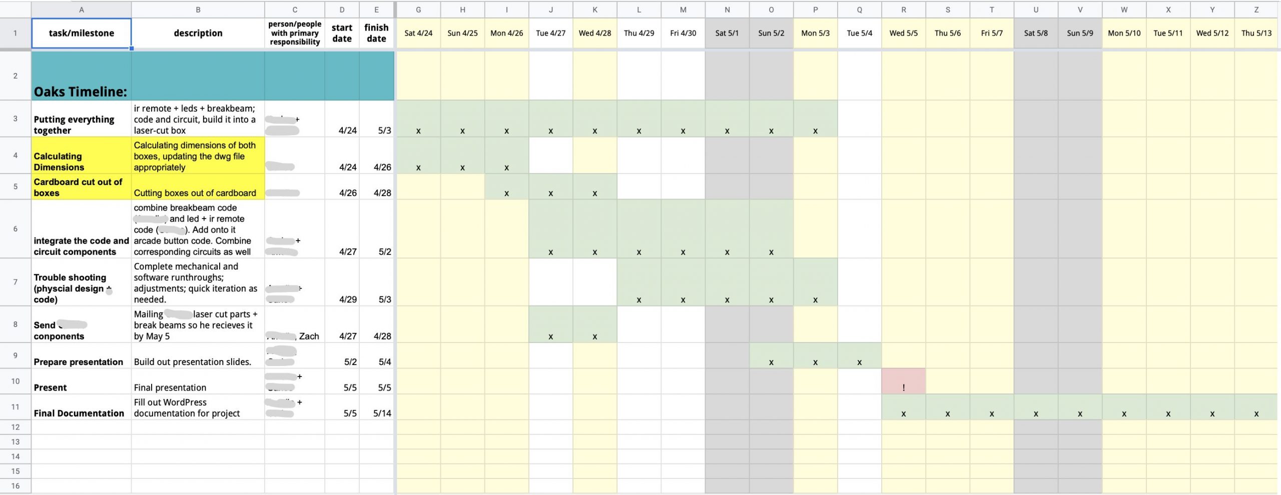
Project management for final build
We stuck to the plan surprisingly well. Making a Gantt chart is immensely useful for project management, as it gives you a super concise way of gauging where you are relative to everything you’ve done and still have to do.
CONCLUSIONS AND LESSONS LEARNED
From the final critique, there were several key findings we discovered from the feedback process. One included the fact that our simple approach to the mini-box was very effective. One critiquer stated “The concept is simple and easy to understand. It also seems to work consistently well.” which we felt was fair. Another positive reviewer stated “the red/green was very simple but effective, really liked the final product!” which we enjoyed seeing. Overall, it seemed that the clean design fulfilled its purpose and wasn’t overly complicated.
In terms of what could’ve made the design more robust, reviewers stated “maybe send a notification to Annie’s phone when she gets mail”, “how easy would it be to read the red / green notification LED from a distance? Maybe an audible alert could help with that” and “it looks like the feedback display is connected to the device by wires so maybe making it connect over Bluetooth or Wifi might improve the flexibility of the device” which are all points we would think about changing in a future iteration of the device. Sending a notification to Annie’s phone would certainty help adapt the device and would probably get rid of the mini-box inside her home so that she would just see the status of her mail through her phone.
A favorite piece of feedback from the critique session (it was given verbally, so it’s hard to quote but this was the idea):
It looks too much like a security system. It could be much more user-friendly; less austere.
I completely agree. We could solve this by making the electronics box rounder, maybe even out of some other material, in another color. The idea would be to make the gadget more huggable.
Working remotely is really difficult, especially working completely off campus, and even more so in different time zones! It was difficult to work without the amazing resources CMU makes available. It makes me so much more grateful for being at CMU!
Having one WordPress editor made it really hard to write the documentation. After having worked on two separate builds, we developed our own unique take on the project, with our own different process. Sometimes it was difficult to progress as a team, rather than as two individuals. Especially while making the documentation, and WordPress’s limitations exacerbated that.
In terms of lessons learned, I believe we were both pleasantly surprised how such a small and simple solution could impact Annie’s daily routine. Not having a disability makes you unaware of all that you take advantage of, and simply walking up to your mailbox everyday is a convivence not everyone is afforded with ease. When we were showing our design to other clients of the class, they reasoned with this hardship and stated that our solution was simple yet effective. Annie described life as being incredibly DIY; she constantly has to find her own solutions to her own challenges, that professional therapists can’t solve. This is why it was so important for Annie to work with a group of very creative young students who are able to solve these problems. We are privileged to have been able to design a solution to help Annie with this task and hope it improves her life.
For next time, we could use a smaller Arduino, like the Nano, for example. For such a simple task, the Arduino Uno feels like overkill. However, the box is already a good size for user interface purposes, so the box itself might have to stay about the same size in order to keep it “huggable.”
Last important lesson: keep it simple.
TECHNICAL DETAILS
Mailbox and gadget concept art
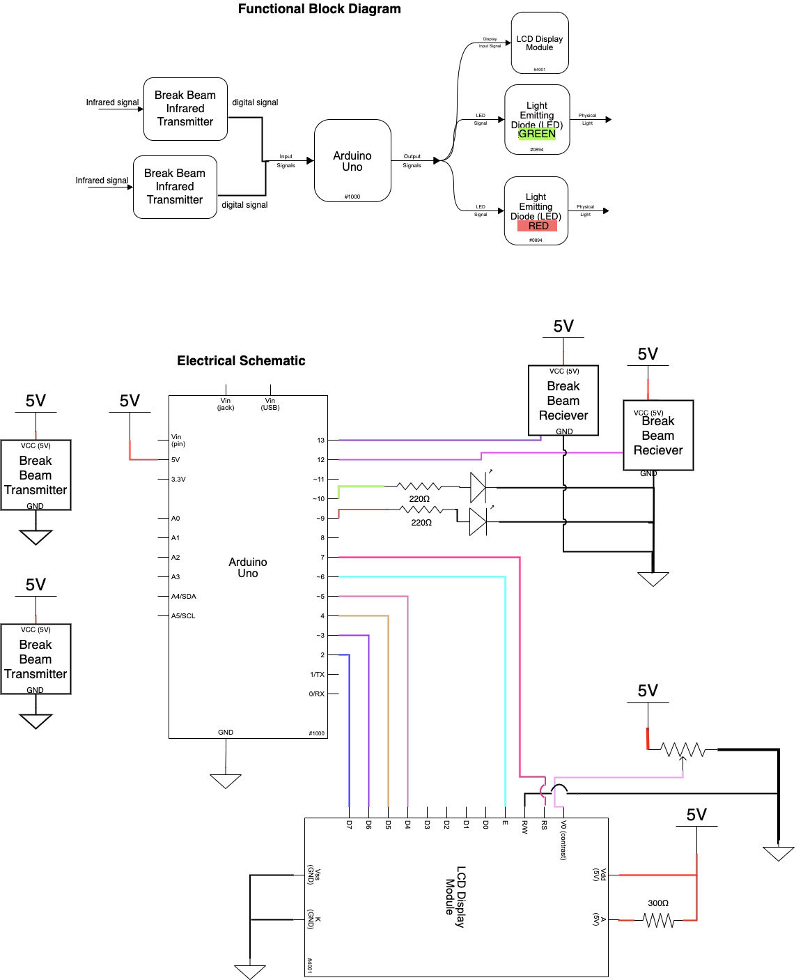
Schematic and Block diagram
Code
/*

  60-223, Final Project
  Amelia Lopez (aelopez)
  Updated by Carlos Ortega on May 2

  Description:
     Reads from 2 breakbeams;
     if at least 1 of them is broken, turns on a green LED
     and updates an LCD screen.
     Turns on the red LED otherwise.

  Challenges:
     Incorporating the IR receiver code would've been challenging,
     but fortunately we didn't use that code at all.
     Deciding how many break beams to incorporate

  Next time:
     Use enumeration type for lcdStatus instead of strings.
     Another version of the code uses 3 breakbeams instead of 2.

  Pin mapping:

   Arduino pin | type   | description
   ------------|--------|-------------
   13            input     BREAK BEAM SENSOR 1
   12            input     BREAK BEAM SENSOR 2
   ~11           input     INFRARED REC. PIN
   ~10           output    GREEN LED
   ~9            output    RED LED
   7             output    LCD RS
   6             output    LCD E
   ~5            output    LCD D4
   4             output    LCD D5
   ~3            output    LCD D6
   2             output    LCD D7

   (digital PWM~)


*/
#include <LiquidCrystal.h>


//DECLARING ARDUINO PINS
const int SENSOR_PIN1 = 13;
const int SENSOR_PIN2 = 12;
const int GREEN_PIN = 10;
const int RECV_PIN = 11;
const int RED_PIN = 9;
const int LCD_RS = 7;
const int LCD_E = 6;
const int LCD_D4 = 5;
const int LCD_D5 = 4;
const int LCD_D6 = 3;
const int LCD_D7 = 2;

//VARIABLE FOR BREAK BEAM
int sensorState1 = 0;
int sensorState2 = 0;
String lcdStatus = "waiting";

//DECLARING INTS FOR LCD WAITING TIMES
const int WAIT_TIME = 300;
unsigned long timeVariable = 0;

// initialize the library by associating any needed LCD interface pin
// with the arduino pin number it is connected to
LiquidCrystal lcd(LCD_RS, LCD_E, LCD_D4, LCD_D5, LCD_D6, LCD_D7);


void setup() {
  //output pins
  pinMode(RED_PIN, OUTPUT);
  pinMode(GREEN_PIN, OUTPUT);

  //input pins
  pinMode(SENSOR_PIN1, INPUT_PULLUP);
  pinMode(SENSOR_PIN2, INPUT_PULLUP);
  digitalWrite(SENSOR_PIN1, HIGH); // turn on the pullup
  digitalWrite(SENSOR_PIN2, HIGH); // turn on the pullup

  // set up the LCD's number of columns and rows:
  lcd.begin(16, 2);

  //print constant letters on screen
  lcd.setCursor(2, 0);
  lcd.print("Mail status: ");

  Serial.begin(9600);
}

void loop() {
  sensorState1 = digitalRead(SENSOR_PIN1);
  sensorState2 = digitalRead(SENSOR_PIN2);

  // turn green LED on if beam is broken (there's mail):
  if (sensorState1 == LOW || sensorState2 == LOW) {
    Serial.println("Broken");
    digitalWrite(GREEN_PIN, HIGH);
    digitalWrite(RED_PIN, LOW);
    lcdStatus = "You've got mail!";
    Serial.println("sensorState1: ");
    Serial.println(sensorState1);
    Serial.println("sensorState2: ");
    Serial.println(sensorState2);
  }
  //turn red LED on (there's no mail)
  else {
    Serial.println("Unbroken");
    digitalWrite(RED_PIN, HIGH);
    digitalWrite(GREEN_PIN, LOW);
    lcdStatus = "    No mail     ";
  }

  //UPDATING VALUES ON LCD
  if (millis() - timeVariable > WAIT_TIME) {
    //updating input sensor value
    lcd.setCursor(0, 1);
    lcd.print(lcdStatus);

    timeVariable = millis();
  }
}
fast forward symbol from: 410160-middle.png