60223 Project 2 – David Wu
Smart Hat with Rotatable Brim
This smart hat can detect where the brightest light is (usually the sunlight), and rotate the brim to face that area- keeping you always in the shade.
Final Project Photos
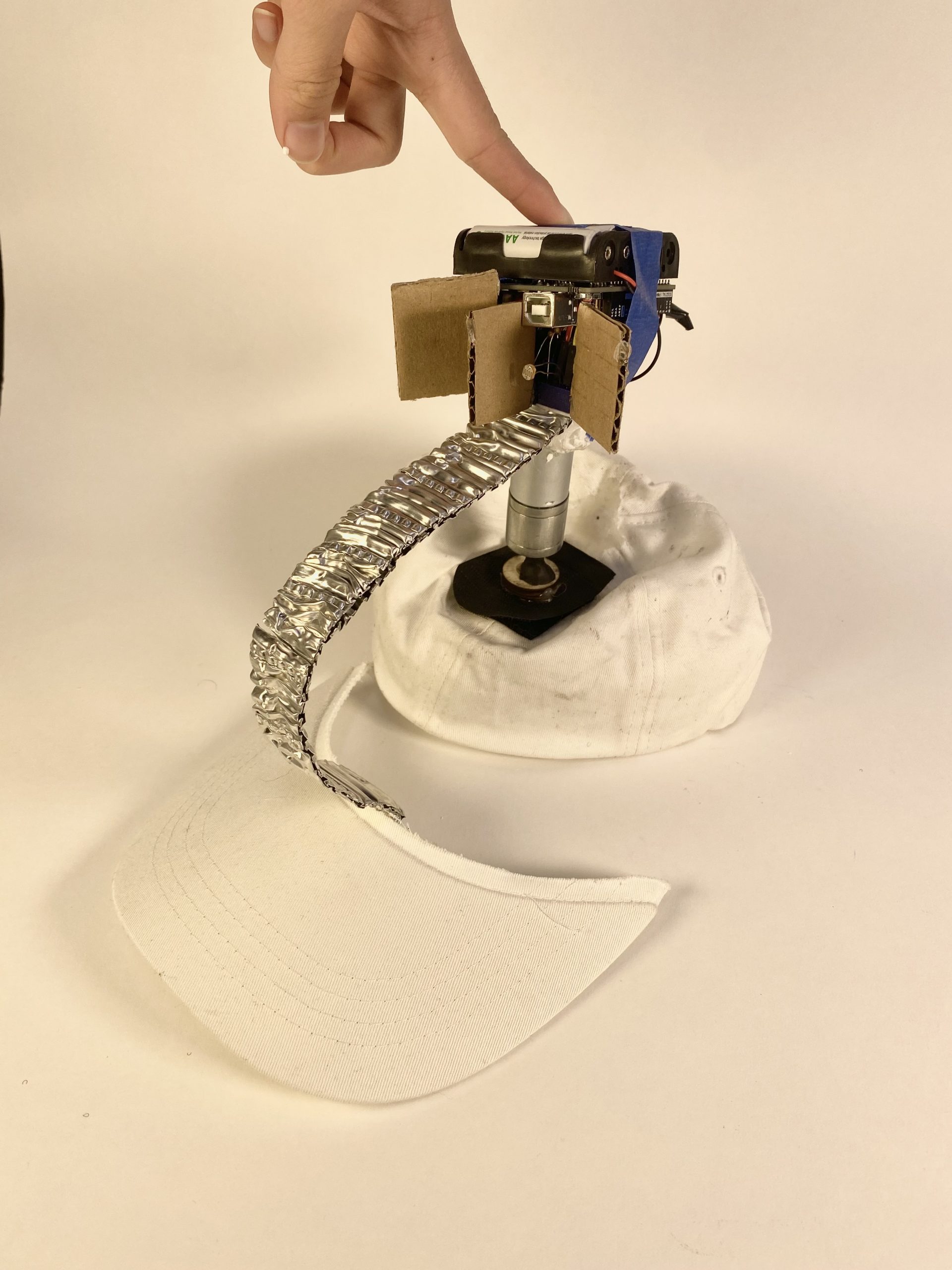
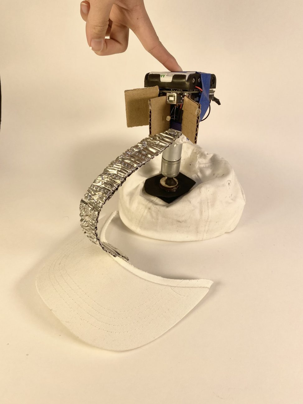
Final product with all components placed together.
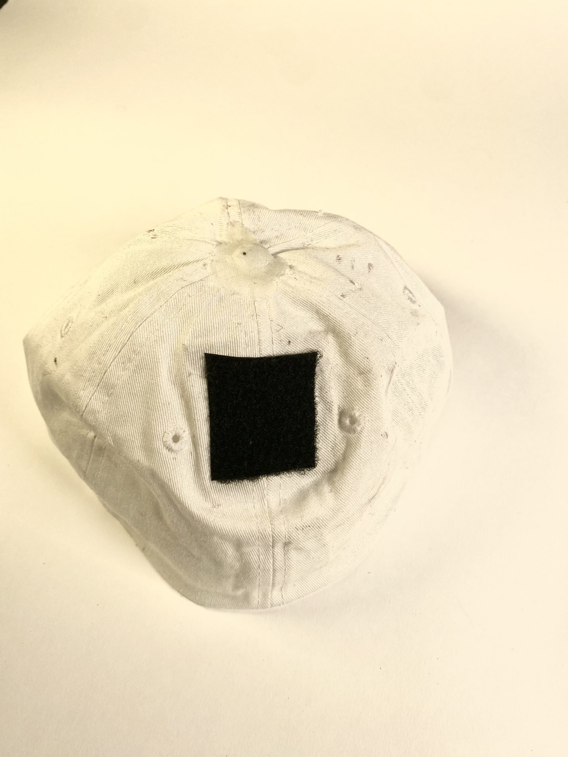
Hat component contains velcro for mechanism attachment.
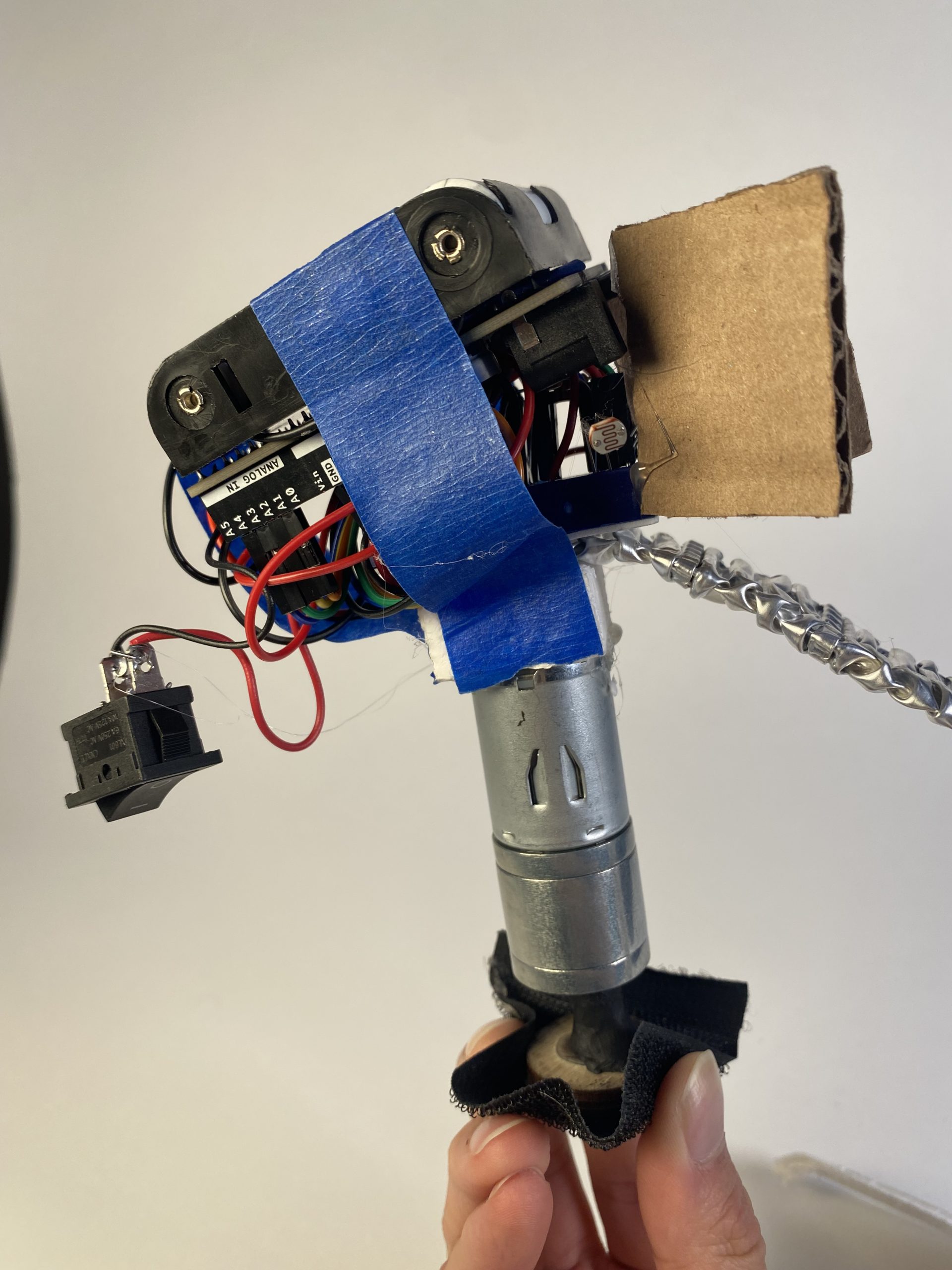
Stand-alone mechanism that sits on top of the hat.
Photoresistors are divided with cardboard to improve light detection accuracy.
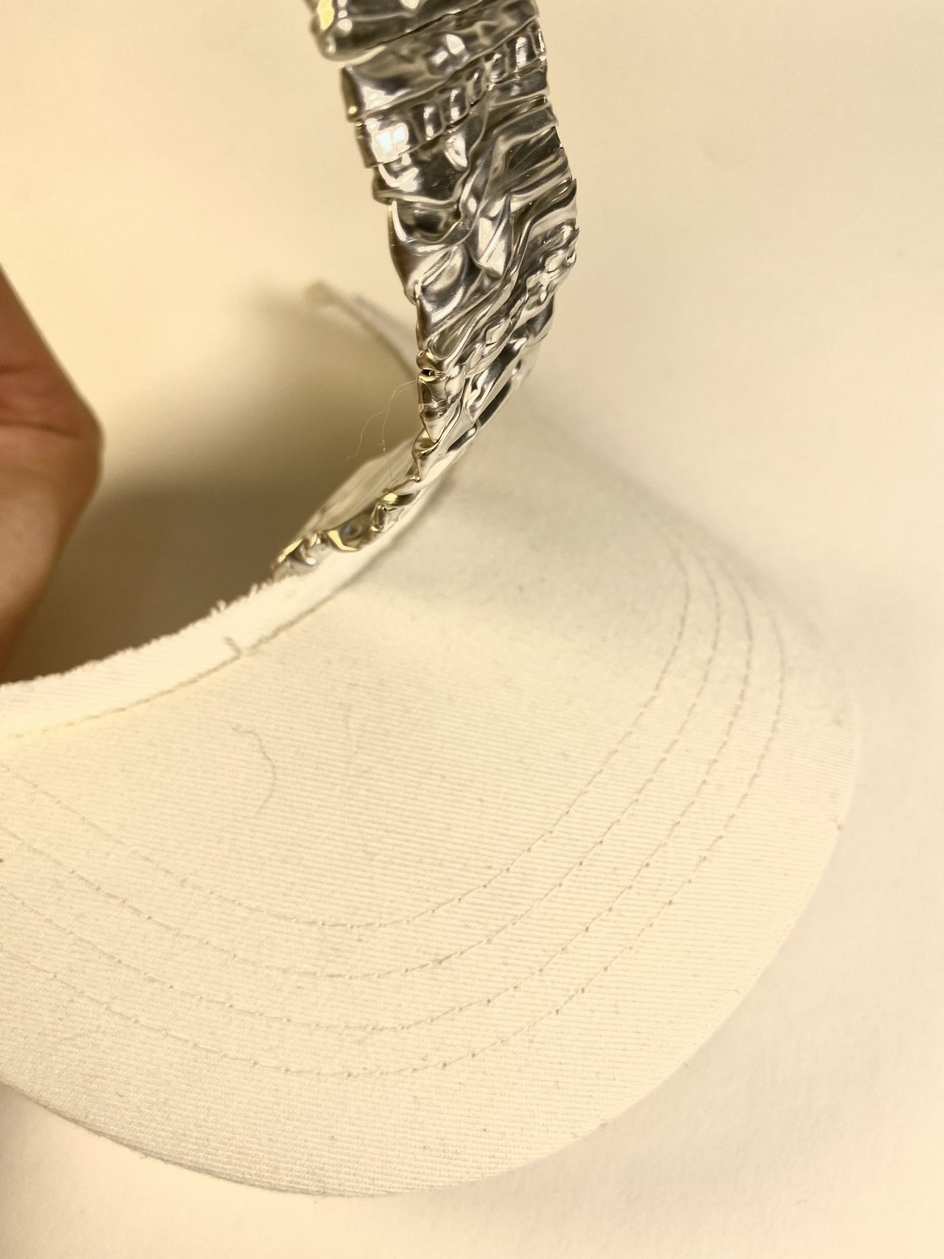
Crushed and cut aluminum foil tubing was used as a support for the brim.
Video Demonstration
Process Review
One key decision point was deciding how to detect the brightest light. There were many ideas here, mostly focused on where and how to arrange the photoresistors. To detect the brightest light, multiple photoresistors would be needed for comparison purposes. A ring of photoresistors attached around the hat (and as such, would be stationary) would offer a way to maintain a “grounded” reference, and as such, one would simply need to turn the motor to the position of the photoresistor with the brightest light detected. This idea was turned down due to the fact that it would require many wires running along the hat, resulting in hat discomfort, but also the fact that when the brim turned to the correct position, it would shade the photoresistor (and making it not detect the brightest light). This latter problem would cause a logical flaw, as it would therefore be impossibly to maintain the hat over the same spot, since the brightest spot would always end up shaded. Thus, the solution had to be that the photoresistors were located above the brim attachment, and that means they had to rotate as well. Putting a ring on top of the motor would work, but in effect, a smarter approach could be used; an entire ring would not be necessary, since we simply need a comparison of brightness. For example, as little as two photoresistors could work, since as long as one is brighter than the other, then we can focus on what direction the motor needed to move to, and not exactly what position it needed to move to. As such, only an arc of photoresistors would be needed, though it is needed to note that having too few photoresistors could lead to inaccuracy, due to low amounts of data collection. Thus, the final product used four photoresistors, employing the smarter approach without sacrificing too much accuracy.
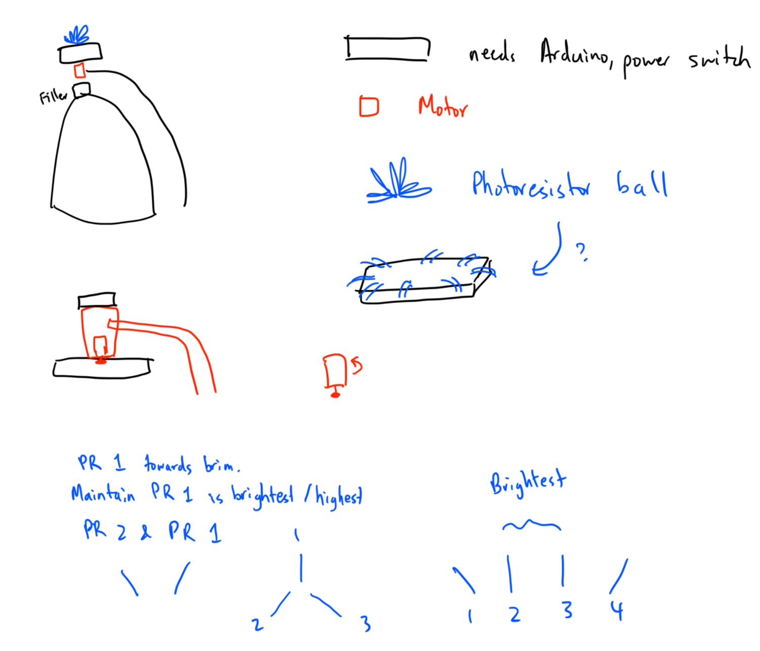
These were initial plans and sketches as to what orientation of photoresistors would be best.
Another key decision point was what motor to use to move the brim. The original approach was with a stepper motor, since it would allow for the most precise 360-degree controlled movement. However, after wiring and playing around with it for a bit, two obvious problems stood out: 1) the physical size and 2) the power source. The stepper motor was incredibly large and heavy, to the point where it could be unreasonable to belong on a head. Due to its hefty proportions and abilities, it also required a 12V power supply- which required an entire extra battery pack. Upon further consideration, I switched to the DC motor for the final product. A DC motor solved both problems- it was smaller and lighter, and it only needed a 6V power supply. The 6V power supply was crucial, since giving it 5V would be sufficient, and that meant it was possible to unify a power supply with the Arduino, who also used a 5V power supply. While DC motors would not be able to control exact position, this can be resolved using the smart method as aforementioned in the previous decision point- exact position does not matter; only direction does. Fortunately, changing the direction of a DC motor was incredibly simple; all that needed to be done was flipping the power and ground voltages of the two pins of the DC motor. The only potential issue was that DC motors had slightly less torque than a stepper motor, but after some testing, this proved to be negligible.
The large size of the stepper motor and extra battery pack caused orientating the mechanism to be difficult and overly bulky.
Process Images
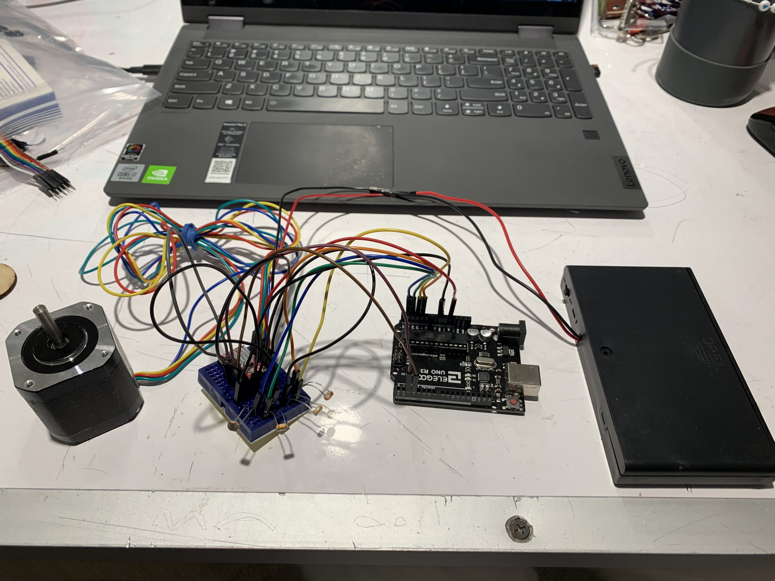
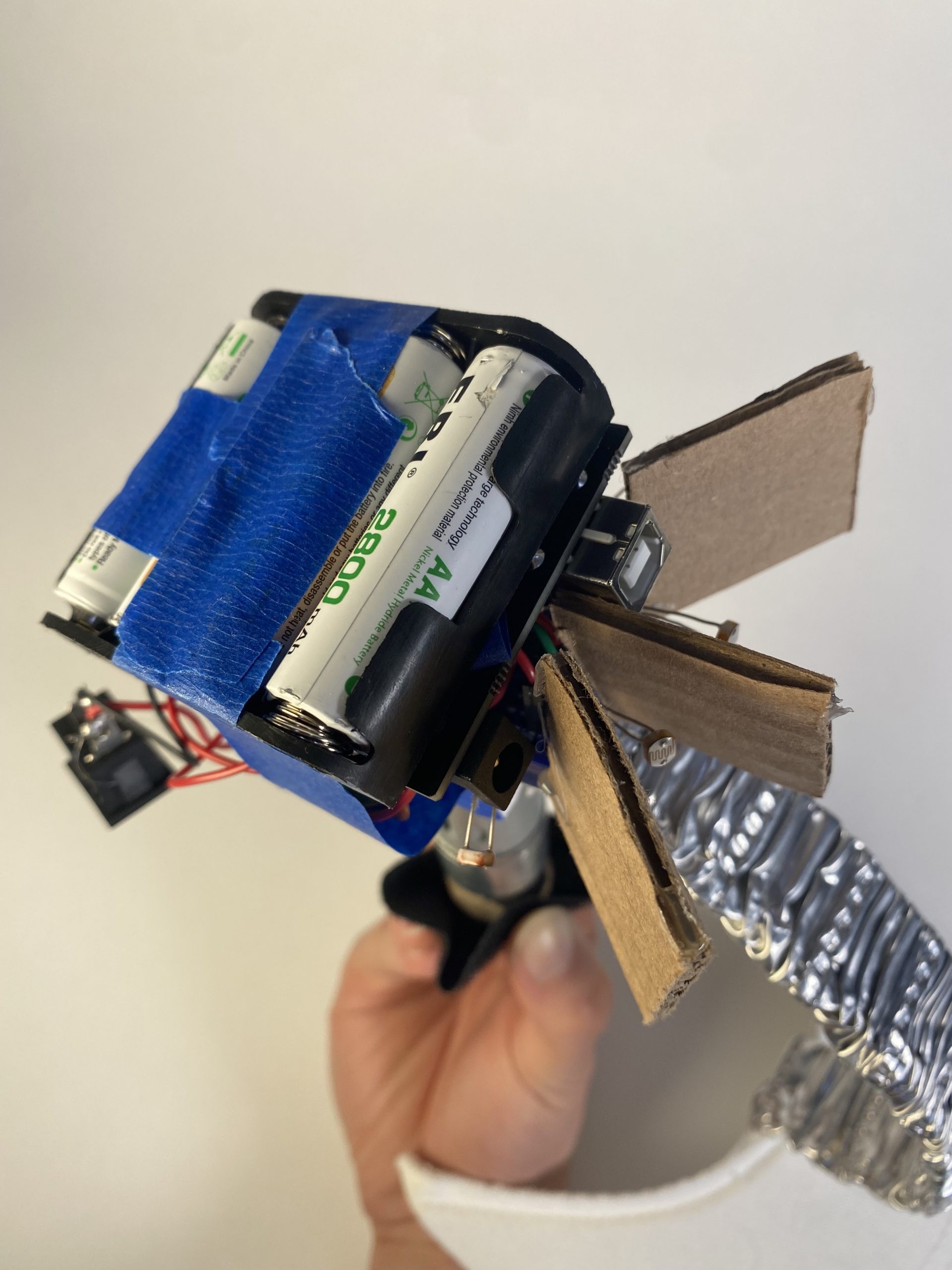
This is the first prototype of the mechanism- with stepper motor and large, extra battery pack.
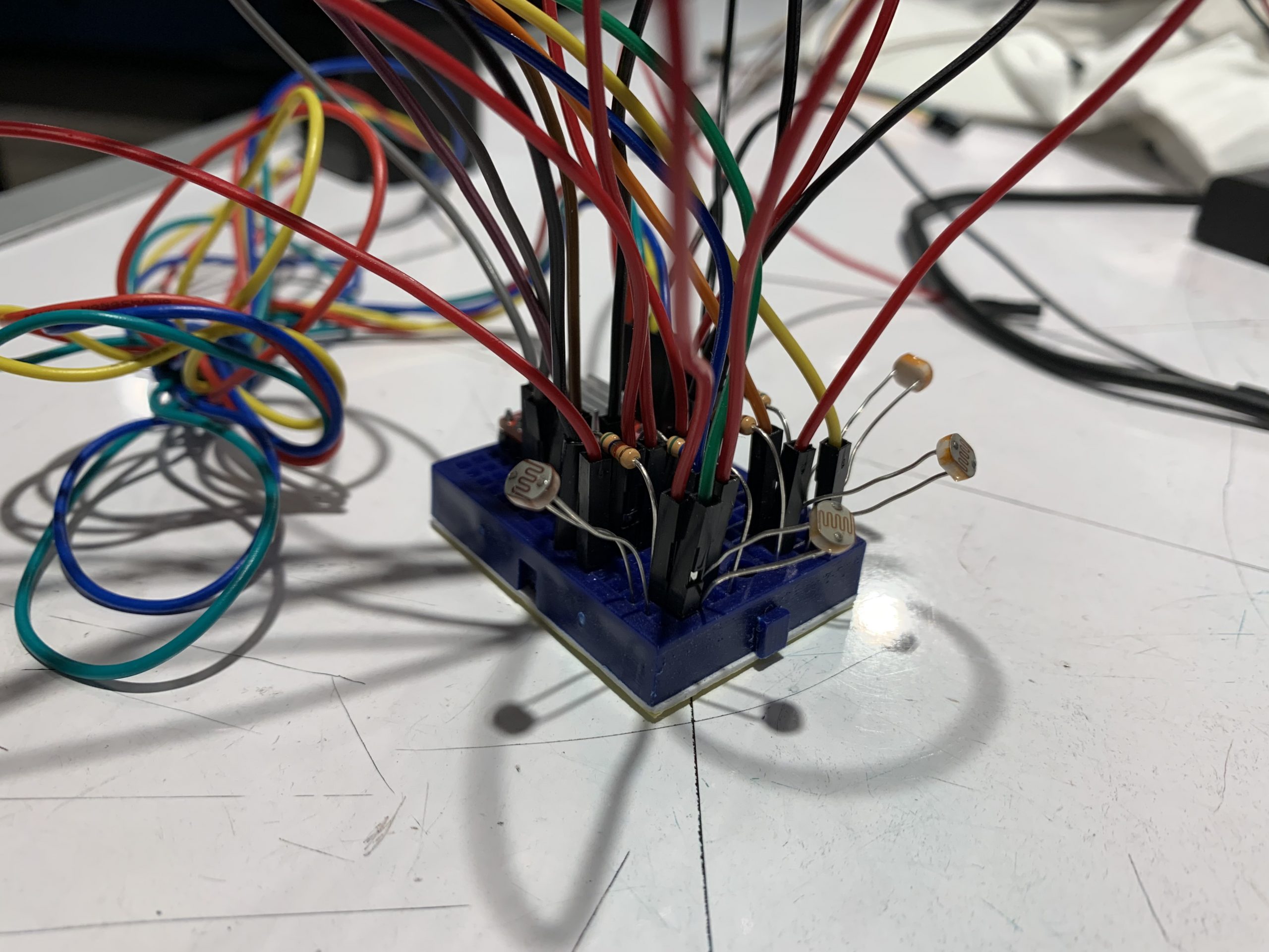
This is an in-depth look at the circuitry involved, primarily focusing on the photoresistors and accompanying resistors.
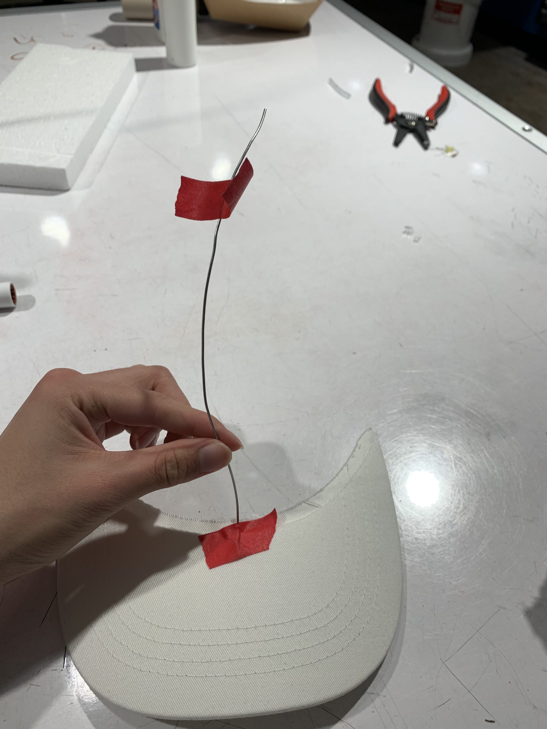
This is initial experimentation as to what material to make the brim support out of.
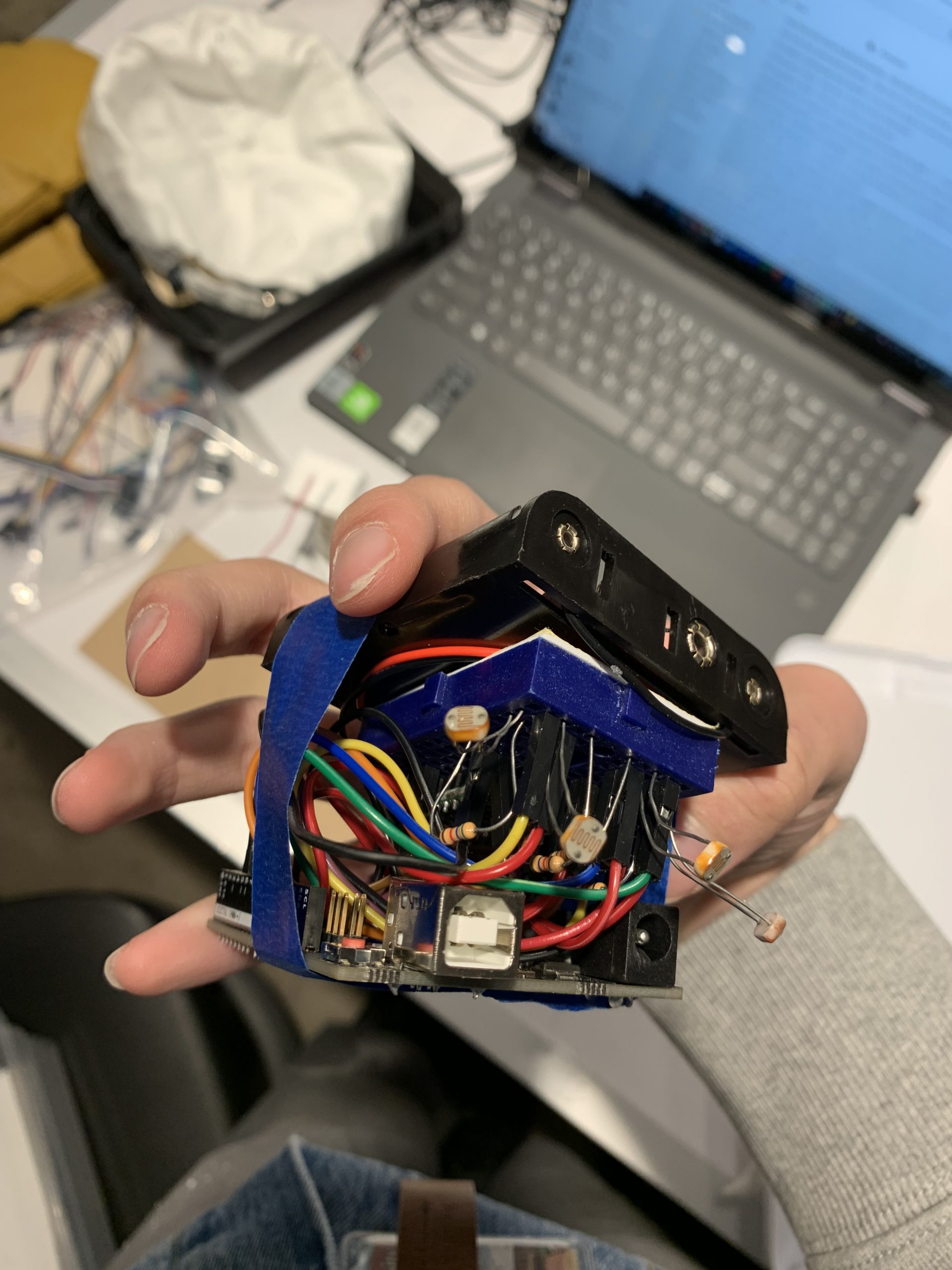
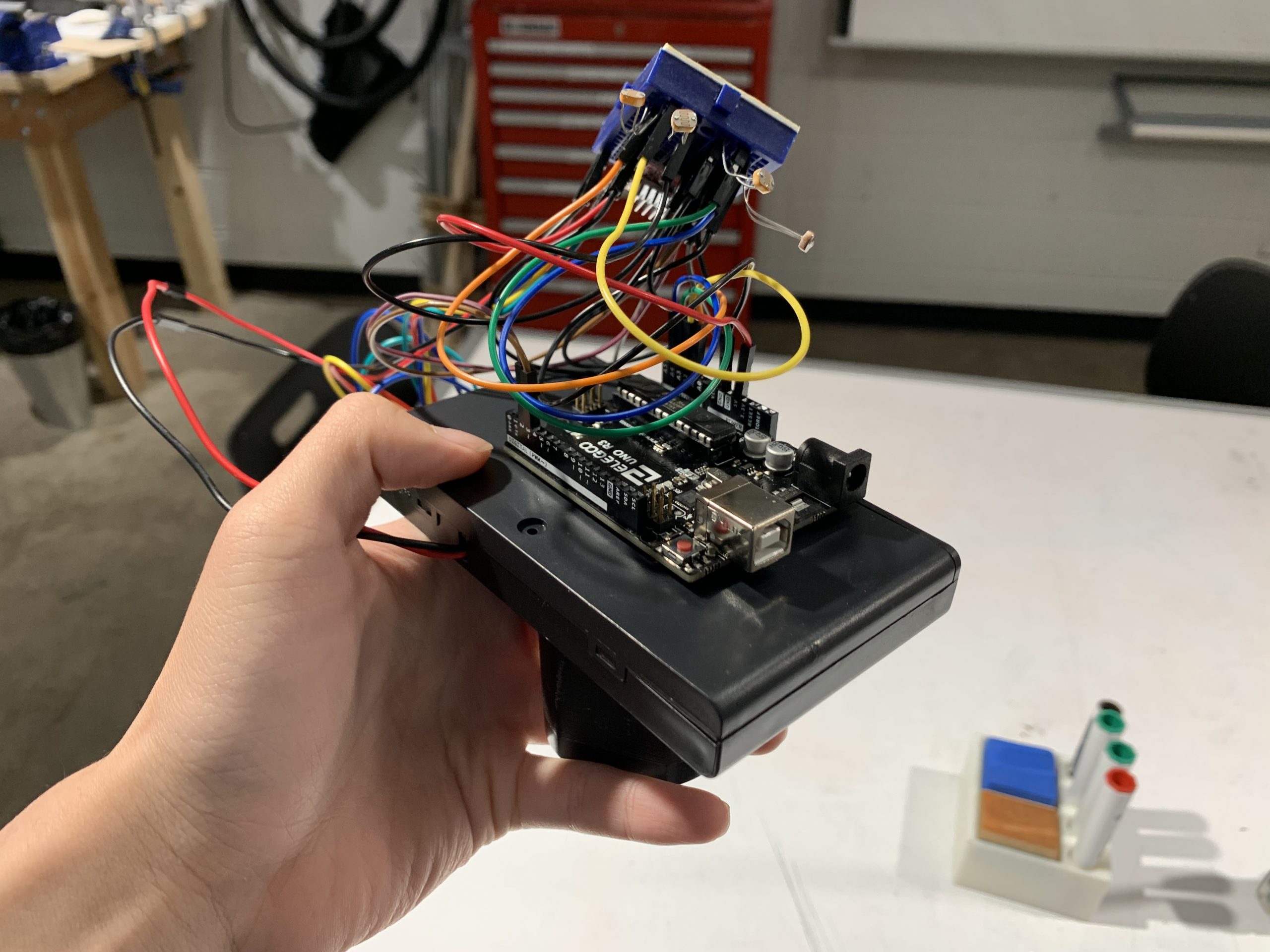
Initial bundling of the electronics together showed promise of a small mechanism.
Everything in the mechanism of the final version is combined- electronics, DC motor, and brim.
Adding a cardboard plating to the inside of the hat was one of many attempts to prevent the mechanism from tilting.
Discussion and Reflection
In general, this project proved to be quite a challenge, and as a result, was good, but not completely perfect. On the bright side (pun not intended), the overall mechanism of the hat worked- the motor rotated the brim towards the brightest light that was detected by the photoresistors. Coding had been relatively straightforward, especially due to the smart method of photoresistor tracking; all that was needed was several comparisons and changing the voltages as necessary.
What failed was the very last step, when everything had to come together. The mechanism proved to be too unbalanced to be placed on the hat. While I had devised six different plans to combat this should it occur, none of them ended up working due to one fatal flaw: the roundness of my head. The original plan was that the hat portion would firmly be on the head, and the mechanism would just be attached to the top. The unfortunate truth was that the mechanism was simply too top-heavy, and the long axle coming out of the motor had a small pivot surface. As such, several attempts to create a wider base for the long axle were made- however, any structure would have a flat surface, and that meant that it would tilt on my head’s roundness. Other attempts to use strong adhesives, like velcro and hot glue, to forcefully and stiffly attach it to the hat did not fully work; while the mechanism was firmly attached to the hat, it would still tilt due to the same original reasons. Cardboard/wood underlays were placed under the cap to try and create a flatter surface on the head, but these did not work, since the underlays themselves would tilt due to my head’s roundness. I thought shifting the location of where the mechanism would be attached to the hat, with similar regards to the comment that I should “add the velcro on the hat to the top center so its on the most “flat” surface of [my] head,” would work, but it turns out no area of my head was flat enough- there was always tilting.
In retrospect, I should have tried more plans, and earlier as well; it was just particularly unfortunate that it was the last step where everything failed. In general, what I managed to do successfully had gone rather smoothly- everything that I struggled in was due to a lack of knowledge. For example, this project affirmed to me that coding-wise, I should not have much problems; while Arduino does have new syntax I still need to learn, it should not be a major issue. I learned about motor differences and usages, how to use AutoCad, etc. There was much to learn, and still is much to learn. The best way to improve my skills is to constantly keep asking for advice on how to approach tasks, and learn as many new techniques as possible. All in all, if anything, learning that I did not learn enough to make this project work completely was a lesson that was valuably learned.
Despite my shortcomings during this project, I do not plan on giving up on making the final product work as intended. I have wanted to build something like this for many years, and it would be silly, after all the advice and information I have learned, to end the project in its current state. I plan to further inquire for assistance regarding their advice, while proceeding further with some ideas of my own. For example, an initial naive idea would be to carve a piece of wood to fit my head’s roundness, while also providing a flat surface on the other side. I also particularly took interest in a comment that I could “wield the [motor’s] rod into an iron helmet,” since an iron helmet (or more probably some metal skeleton) would eliminate the need for a flat surface (they would be conjoined) and still have the shape for my head. Whatever the final changes may be, I plan to complete this project, and come to school wearing it in all of its hilarious and quirky glory.
Functional Block Diagram and Schematic

Project Code
/* Project Title: Smart Hat with Rotatable Brim
 * Creator: David Wu
 *
 * This code takes in the input of four photoresistors to
 * find the brightest light source, and then, if needed,
 * rotates the brim of the hat in that general direction
 * by flip-flopping the voltages on the pins of the DC motor.
 * The brim is centered between the second and third
 * photoresistors. The code is adaptable to left-right
 * orientation (physical implementation of the four photoresistors
 * does not matter as it just requires re-defining which
 * direction the brim will turn).
 *
 * Pin Mapping:
 * Photoresistor 1 : A0
 * Photoresistor 2 : A1
 * Photoresistor 3 : A2
 * Photoresistor 4 : A3
 * DC Pin 1        : 5
 * DC Pin 2        : 6
 *
 */

const int DCPIN1 = 5; // DRV8833 B1 in
const int DCPIN2 = 6; // DRV8833 B2 in
const int PHOTOPIN1 = A0;// photoresistor input
const int PHOTOPIN2 = A1;// photoresistor input
const int PHOTOPIN3 = A2;// photoresistor input
const int PHOTOPIN4 = A3;// photoresistor input
int timer = 0; // to slow down motor responsiveness

void setup() {
  pinMode(PHOTOPIN1, INPUT);
  pinMode(PHOTOPIN2, INPUT);
  pinMode(PHOTOPIN3, INPUT);
  pinMode(PHOTOPIN4, INPUT);
  pinMode(DCPIN1, OUTPUT);
  pinMode(DCPIN2, OUTPUT);
  Serial.begin(9600);
}

void loop() {
  // prevent motor from switching too quickly and minimize jittering
  if(millis() - timer >= 500) {
    // read photoresistor values (0 - 1023)
    int bright1 = analogRead(PHOTOPIN1);
    int bright2 = analogRead(PHOTOPIN2);
    int bright3 = analogRead(PHOTOPIN3);
    int bright4 = analogRead(PHOTOPIN4);

    // calculate the brightest spot
    int max12 = max(bright1, bright2);
    int max34 = max(bright3, bright4);
    int maxBright = max(max12, max34);

    // if brightest is at center (where brim is)
    if((bright2 == maxBright) && (bright3 == maxBright)){
      // don't move the motor
      analogWrite(DCPIN1, 0);
      analogWrite(DCPIN2, 0);
    }
    // if brightest is to the left
    else if ((bright1 == maxBright) || (bright2 == maxBright)){
      // rotate brim to the left
      analogWrite(DCPIN1, 0);
      analogWrite(DCPIN2, 128);
    }
    // if brightest is to the right
    else{
      // rotate brim to the right
      analogWrite(DCPIN1, 128);
      analogWrite(DCPIN2, 0);
    }
    timer = millis();
  }
}