Task Box
This project is a modular physical to do list that allows the user to customize which tasks they do each day. It tracks task completion and task progress.
Images:
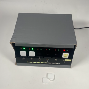
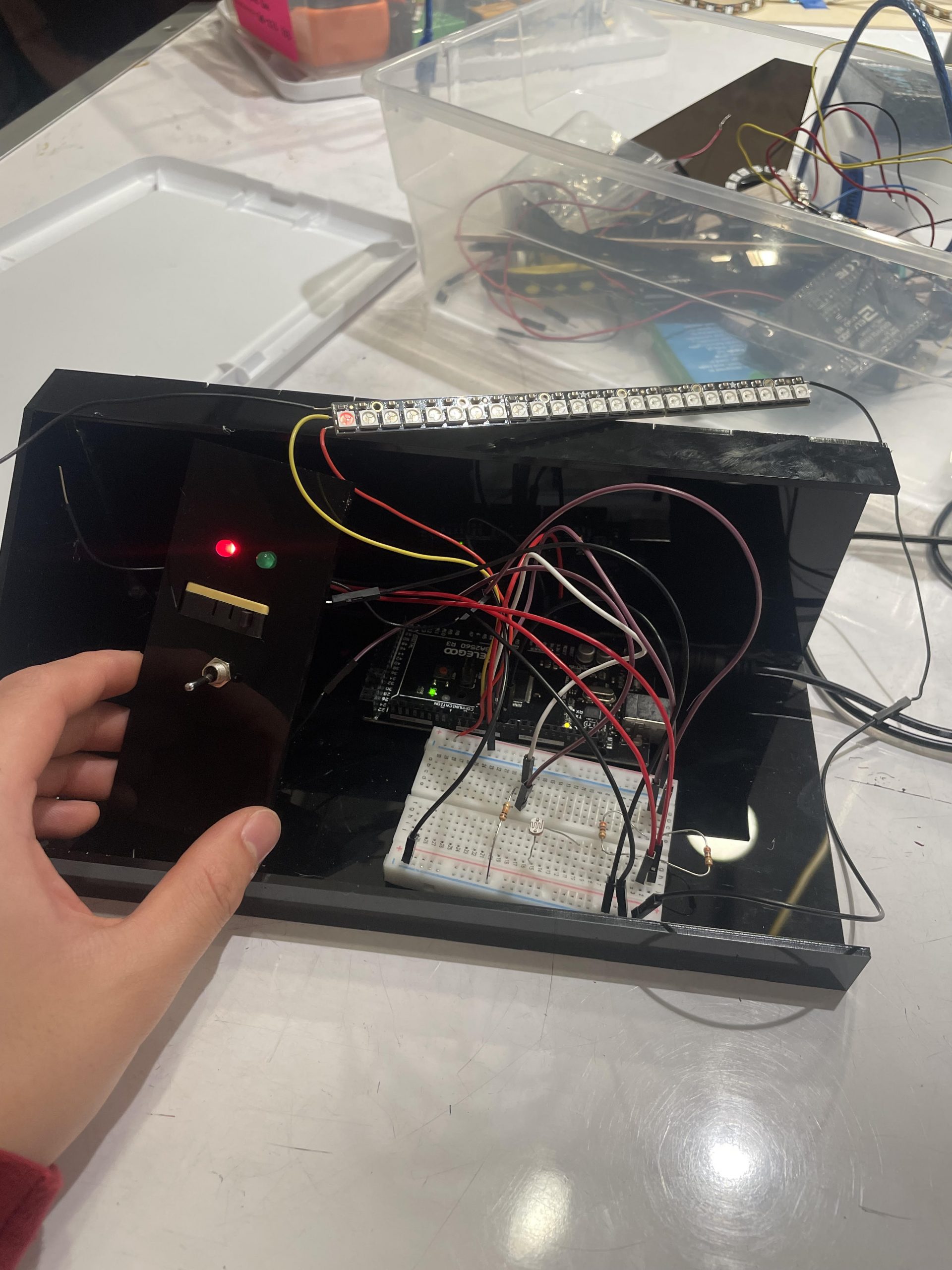
Top view of device
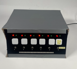
All Front Switches flipped to red; indicating 0% completion
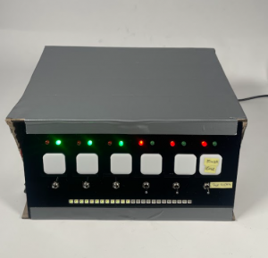
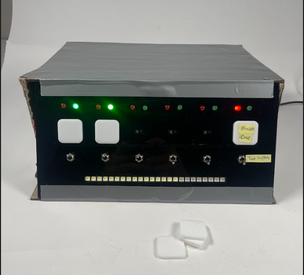
Half of the switches are flipped to complete, the top row of LED’s show individual task progress, the progress bar on the bottom shows % of tasks complete.
Process images and review:
Key Decision points
The first decision point came after prototyping a switch panel. The initial idea was to use a limit switch to detect the presence of a tile. After fabricating a sample switch it was determined that it would be difficult to create a tile system that was strong enough to toggle the switches. From this prototype, I decided to use IR proximity sensors instead to track tile placements.

The second decision point occurred after completing the full wiring for the device as pictured above. It was clear that I had underestimated the amount of space that all of the wires would take up, thus the acrylic casing that I had cut for to store the wires was far too small. Given limited time and resources, my solution was to construct a temporary larger box out of chipboard for the presentation, and then redesign the outer case at a later date.
Process
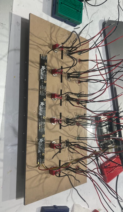
This is the Completed front panel. consisting of 12 LED’s 6 switches, 6 IR sensors, and 3 Neopixel light strips. There are also slots precut for tile placement as well as a hinge hole located in the top to aid with electronic access in the final product.
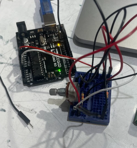
This is a sample circuit that I made in order to run test code for IR proximity sensor as well as check sensors for any defects. The final version uses the same circuit.
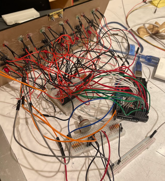
This is the completed wiring for the number 6 IR proximity sensor, at this point in the project the switches and LED’s are already wired and working. The remaining step is to wire the other 5 IR sensors and adjust the code to incorporate them. The wiring process was very time consuming, but troubleshooting issues was less difficult than expected due to my diligence with color coding. The final version required 1.5 full breadboards and 2 additional power rails.
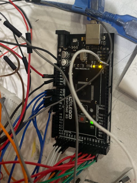
Here is the completed Arduino wiring. The color coding is as follows, Green: Green LED power, Red: Red LED power, White: toggle switch signal, Blue: IR sensor signal. There is also additional wiring in the device not pictured above that follow an equally strict color convention. Black: Ground from switches/LED’s/Colorstrip/Pulldown resistors/IR emitter, Grey: Ground from IR photoresistor, Red: Power for LED’s/Colorstrip/IR emittor, Orange: Power for IR sensor. Brown/Yellow: Power in between all of the subsystems.
Discussion:
I am overall pleased with the outcome of the project and intend to use it myself. The presentation also went relatively smoothly. Looking at the critique comments one person noted that “Make it smaller if possible. I thought the finish a circuit idea was really good.” For the first part of the comment, I would agree with the recommendation. Given the relative simplicity of the devices operation, it would be nice for the design to be less invasive in terms of the amount of space that it would take up. Ideally it would be a small box that sits on my desk as per the initial design. However, as the device is constructed currently, creating a new smaller casing would not be feasible as the amount of wiring restricts the minimum size of the casing. I think that in order to achieve a sleeker design, it would require major rewiring to shorting the existing wires and soldering every connection such that the process of cramming the wires into a case does not affect the connections. The second half of this critique was commenting on tile detection methods. I initially experimented with using conductive tape to bridge a circuit to indicate the presence of a tile. This was with the intention that I could add resistances into the tiles that the Arduino could measure to encode tasks. Since then I have discovered the IR sensor solution which I think is better than the solution that the critique proposes. I think that the IR sensors are easier to work with, require less manufacturing of each tile, and are still task encodable by using different color acrylic. Another comment from the critique noted: “I really like the idea and the tactility to it makes it more satisfying. “. It was my intention to create a lot of tactile, auditory, and visual feedback from completing a task to create a system that is more satisfyingly than conventionally marking off a to do list. I’m glad to hear that there is some consensus that the design that I envisioned has a similar satisfying aspect to others.
The final presented project works as intended. I am a little upset that the sleek black casing could not be shown during the presentation but I intend on making a new case for my own use. The operation of the devices is exactly as I envisioned and I think that this will be genuinely useful for my everyday life. For this project, I wanted to build upon the skills from project 1 and ultimately create a devices with a better aesthetic and design than project 1, and create a deceives with significantly higher consistency and durability than my project 1. I think that even though the end product was not what I had envisioned, I have sufficiently met these two goals.
The process of creating this project was filled with significantly more complications than project 1. Unlike many in this class, I have no background in creative or practical design or much experience with fabrication. Being a Statistics and Machine learning major, my strength lies in the coding portion of this project. I intentionally decided on a device where aesthetic, design, and construction would be more challenging and coding would be rather simple in order to work on those skills. If I had more time, I would’ve liked to go through multiple iterations of the design portion. Unfortunately, with limited time and resources, I was not able to adjusted the design of the case as I would have liked to. I also underestimated the amount of time and the difficulty of the wiring of the final product. I had constructed multiple little circuits of each component prior to the final assembly in order to finalize circuit layout and also test each part for defects, but when combining all of the components together, it was very difficult to plug things in and organize stuff with the quantity of wires I was working with. A large reason was due to some of the wires from my components being too short, this either restricted the location of breadboards, or necessitated extending the wire with a new one and heat shrink. Both resulted in complications that took a lot of time to resolve. For the future, when I anticipated complicated wiring, I would cut longer leads for components as well as consider using softer more flexible wires.
I have a lot of ideas for improvements and iterations for this project. Firstly, I will design and create a new casing for the version that I already have so that I can use it on my desk. I intend on doing this within the next couple of weeks as time permits. This will probably be the only thing that I do with regards to project 2, however, If I were to build another version, I have many improvements that I’d pursue.
The first adjustment would be encoding tasks with different color tiles. This would primarily be a coding change as the sensors have the capability of distinguishing between colors. another adjustment would be implementing a photoresistor that would detect external lights. Since the LED’s are quite bright, I wouldn’t want them to be on if I am sleeping. This photoresistor would turn all lights off if the surrounding room is dark. In addition to these new features, I would also like to make the wiring changes that I previously talked about in this next iteration.
Technical Information:

/*
Project Name: Task Box

Author: Harry Ren

- tracks tile placement with 6 IR proximity sensors
- tracks task completeness with 6 toggle switches
- uses information to light up 12 LED's signaling task completeness

Pin Mapping:
A0-A5: IR Proximity Sensor Out 1-6
3: LED Data IN
24,26,28,30,32,34: Red LED Pwr Out 1-6
25,27,29,31,33,35: Green LED Pwr Out 1-6
46-51: Switch Pwr IN 1-6

Portions of code are adapted from the following sources
- NEOPIXEL by ADAFRUIT example: strandtest
relevant functions are credited

code by Harry Ren at Carnegie Mellon University (hjren@andrew.cmu.edu)
released by author to public domain, Mar 2023
*/


#include <Adafruit_NeoPixel.h>
#include <Servo.h>
#include <NewPing.h>
#include <Wire.h>
#include <LiquidCrystal_I2C.h>
#ifdef __AVR__
#include <avr/power.h>  // Required for 16 MHz Adafruit Trinket
#endif

// Neopixel connection Pin?
#define LED_PIN 3
// How many NeoPixels are attached to the Arduino?
#define LED_COUNT 24
// Declare our NeoPixel strip object:
Adafruit_NeoPixel strip(LED_COUNT, LED_PIN, NEO_GRB + NEO_KHZ800);

//Set Pin constants
//LEDS
const int r1 = 24;
const int g1 = 25;
const int r2 = 26;
const int g2 = 27;
const int r3 = 28;
const int g3 = 29;
const int r4 = 30;
const int g4 = 31;
const int r5 = 32;
const int g5 = 33;
const int r6 = 34;
const int g6 = 35;
//Switches
const int sw1 = 51;
const int sw2 = 50;
const int sw3 = 49;
const int sw4 = 48;
const int sw5 = 47;
const int sw6 = 46;
//IR sensors
const int sensor6 = A0;
const int sensor5 = A1;
const int sensor4 = A2;
const int sensor3 = A3;
const int sensor2 = A4;
const int sensor1 = A5;

void setup() {

  pinMode(sw1, INPUT);
  pinMode(sw2, INPUT);
  pinMode(sw3, INPUT);
  pinMode(sw4, INPUT);
  pinMode(sw5, INPUT);
  pinMode(sw6, INPUT);

  pinMode(r1, OUTPUT);
  pinMode(g1, OUTPUT);
  pinMode(r2, OUTPUT);
  pinMode(g2, OUTPUT);
  pinMode(r3, OUTPUT);
  pinMode(g3, OUTPUT);
  pinMode(r4, OUTPUT);
  pinMode(g4, OUTPUT);
  pinMode(r5, OUTPUT);
  pinMode(g5, OUTPUT);
  pinMode(r6, OUTPUT);
  pinMode(g6, OUTPUT);

  pinMode(sensor6, INPUT);
  pinMode(sensor5, INPUT);
  pinMode(sensor4, INPUT);
  pinMode(sensor3, INPUT);
  pinMode(sensor2, INPUT);
  pinMode(sensor1, INPUT);


  Serial.begin(9600);

  strip.begin();           // INITIALIZE NeoPixel strip object (REQUIRED)
  strip.show();            // Turn OFF all pixels ASAP
  strip.setBrightness(1);  // Set BRIGHTNESS to about 1/5 (max = 255)
}

void loop() {

  int threshold = 800;
  //boolean flags for if tile exists
  int tilebool6 = false;
  int tilebool5 = false;
  int tilebool4 = false;
  int tilebool3 = false;
  int tilebool2 = false;
  int tilebool1 = false;

  int sen6 = analogRead(sensor6);
  int sen5 = analogRead(sensor5);
  int sen4 = analogRead(sensor4);
  int sen3 = analogRead(sensor3);
  int sen2 = analogRead(sensor2);
  int sen1 = analogRead(sensor1);


  //adjust flags given sensor readings
  if (sen6 > threshold) {
    tilebool6 = true;
  }
  if (sen5 > threshold) {
    tilebool5 = true;
  }
  if (sen4 > threshold) {
    tilebool4 = true;
  }
  if (sen3 > threshold) {
    tilebool3 = true;
  }
  if (sen2 > threshold) {
    tilebool2 = true;
  }
  if (sen1 > threshold) {
    tilebool1 = true;
  }
  //set light on booleans
  bool tag1 = false;
  int on1 = 0;
  int on2 = 0;
  int on3 = 0;
  int on4 = 0;
  int on5 = 0;
  int on6 = 0;
  //read switches
  int switch1 = digitalRead(sw1);
  int switch2 = digitalRead(sw2);
  int switch3 = digitalRead(sw3);
  int switch4 = digitalRead(sw4);
  int switch5 = digitalRead(sw5);
  int switch6 = digitalRead(sw6);

  //tile 1 logic
  if (tilebool1) {
    if (switch1 == 0) {
      digitalWrite(g1, HIGH);
      digitalWrite(r1, LOW);
      on1 = 1;
    } else {
      digitalWrite(r1, HIGH);
      digitalWrite(g1, LOW);
      on1 = 0;
    }
  } else {
    digitalWrite(r1, LOW);
    digitalWrite(g1, LOW);
  }
  //tile 2 logic
  if (tilebool2) {
    if (switch2 == 0) {
      digitalWrite(g2, HIGH);
      digitalWrite(r2, LOW);
      on2 = 1;

    } else {
      digitalWrite(r2, HIGH);
      digitalWrite(g2, LOW);
      tag1 = true;
      on2 = 0;
    }
  } else {
    digitalWrite(r2, LOW);
    digitalWrite(g2, LOW);
  }
  //tile 3 logic
  if (tilebool3) {
    if (switch3 == 0) {
      digitalWrite(g3, HIGH);
      digitalWrite(r3, LOW);
      on3 = 1;

    } else {
      digitalWrite(r3, HIGH);
      digitalWrite(g3, LOW);
      tag1 = true;
      on3 = 0;
    }
  } else {
    digitalWrite(r3, LOW);
    digitalWrite(g3, LOW);
  }
  //tile 4 logic
  if (tilebool4) {
    if (switch4 == 0) {
      digitalWrite(g4, HIGH);
      digitalWrite(r4, LOW);
      on4 = 1;

    } else {
      digitalWrite(r4, HIGH);
      digitalWrite(g4, LOW);
      tag1 = true;
      on4 = 0;
    }
  } else {
    digitalWrite(r4, LOW);
    digitalWrite(g4, LOW);
  }
  //tile 5 logic
  if (tilebool5) {
    if (switch5 == 0) {
      digitalWrite(g5, HIGH);
      digitalWrite(r5, LOW);
      on5 = 1;

    } else {
      digitalWrite(r5, HIGH);
      digitalWrite(g5, LOW);
      tag1 = true;
      on5 = 0;
    }
  } else {
    digitalWrite(r5, LOW);
    digitalWrite(g5, LOW);
  }

  //tile 6 logic
  if (tilebool6) {
    if (switch6 == 0) {
      digitalWrite(g6, HIGH);
      digitalWrite(r6, LOW);
      on6 = 1;

    } else {
      digitalWrite(r6, HIGH);
      digitalWrite(g6, LOW);
      tag1 = true;
      on6 = 0;
    }
  }

  else {
    digitalWrite(r6, LOW);
    digitalWrite(g6, LOW);
  }
  delay(10);


  //progress bar calculations and display code
  int number_in_use = tilebool1 + tilebool2 + tilebool3 + tilebool4 + tilebool5 + tilebool6;
  int number_complete = on1 + on2 + on3 + on4 + on5 + on6;

  int lightperon = (int)24 / float(number_in_use);
  int colscale = (int)300 / float(number_in_use);

  //edge case for 5 tiles
  if (number_in_use == 5) {
    lightperon = 5;
  }
  strip.clear();

  //neopixel bar code
  for (int i = 0; i < number_complete * lightperon; i++) {
    //Serial.print(i);
    strip.setPixelColor(i, get_col(colscale * number_complete));
  }
  strip.show();
}

//helper func to get color value from project 1
uint32_t get_col(int i) {
  //red to yellow
  if (i < 170) {
    i = map(i, 0, 170, 0, 255);
    return strip.Color(255, i, 0);
  }
  //yellow to green
  else if (i < 340) {
    i = map(i, 170, 340, 0, 255);
    return strip.Color(255 - i, 255, 0);
  }
  //green to cyan
  else if (i < 510) {
    i = map(i, 340, 510, 0, 255);
    return strip.Color(0, 255, i);
  } else if (i < 680) {
    i = map(i, 510, 680, 0, 255);
    return strip.Color(0, 255 - i, 255);
  } else if (i < 850) {
    i = map(i, 680, 850, 0, 255);
    return strip.Color(i, 0, 255);
  } else {
    i = map(i, 850, 1023, 0, 255);
    return strip.Color(255, i, 255);
  }
}