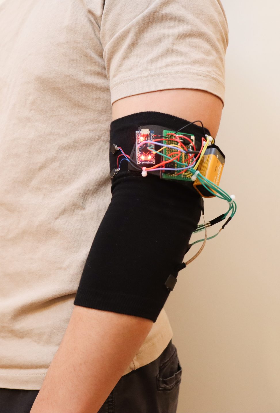
An elbow sleeve that vibrates when your elbow is bent past 90 degrees for too long, and when you put excessive pressure on your elbow joint.
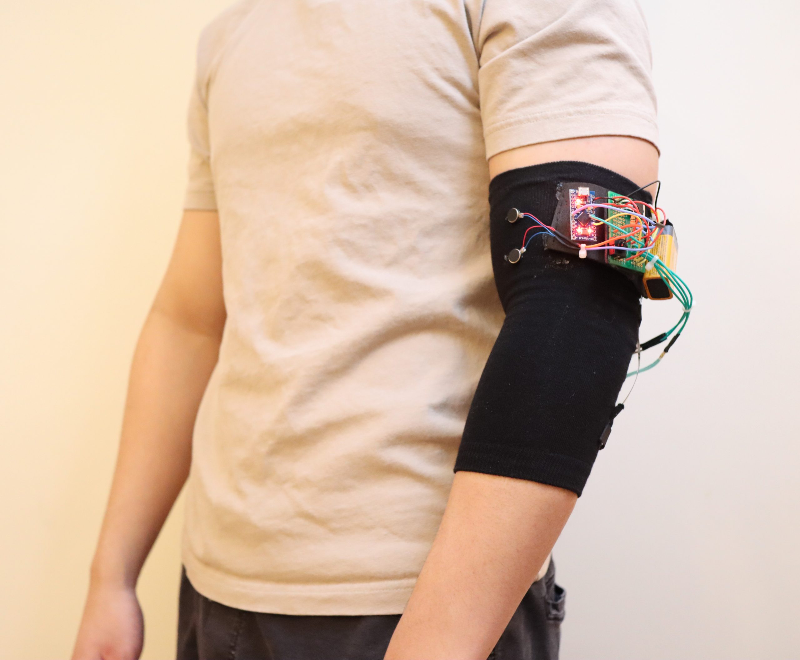
Fits around halfway up your upper arm, and covers the elbow. Pancake vibration motors are placed over the bicep.
Fabric is elastic and bends with the elbow without restriction
Flex sensor and pressure sensors located under the elbow joint.
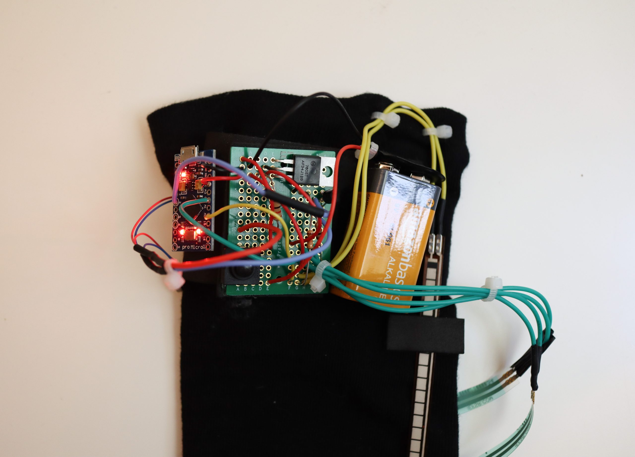
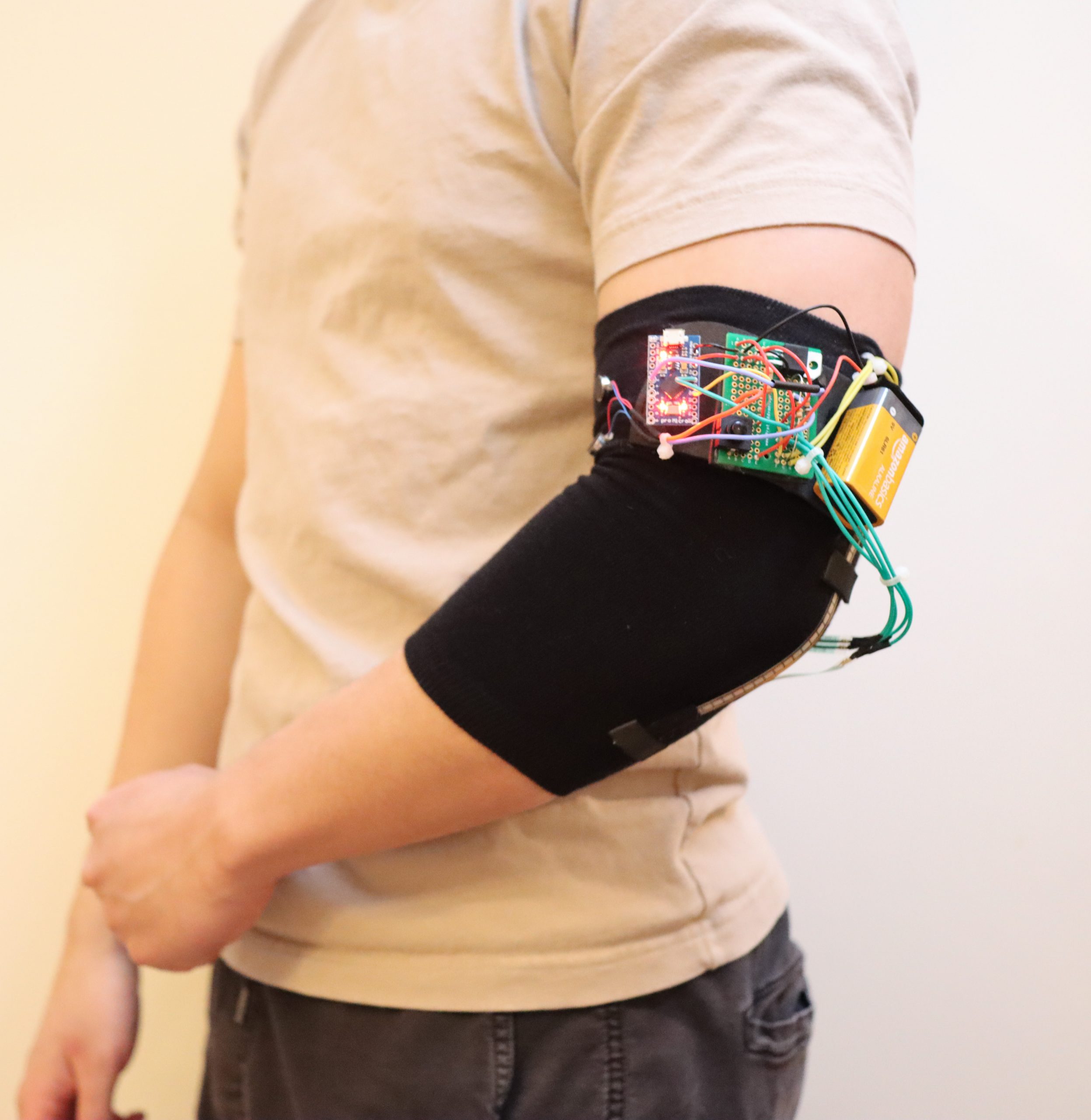
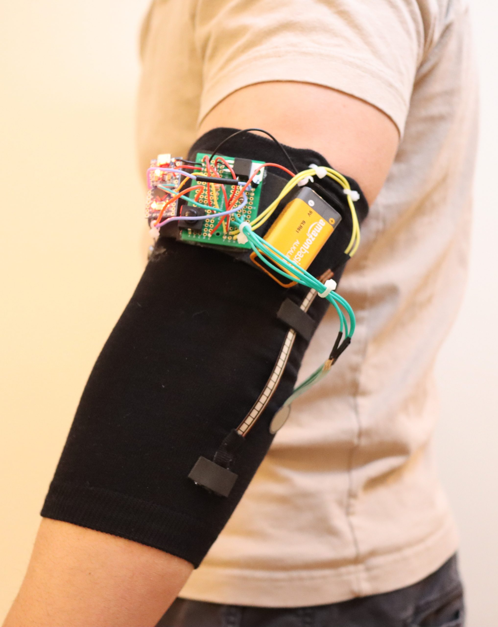
Arduino Pro Micro powered by a 9V battery. All connections are soldered.
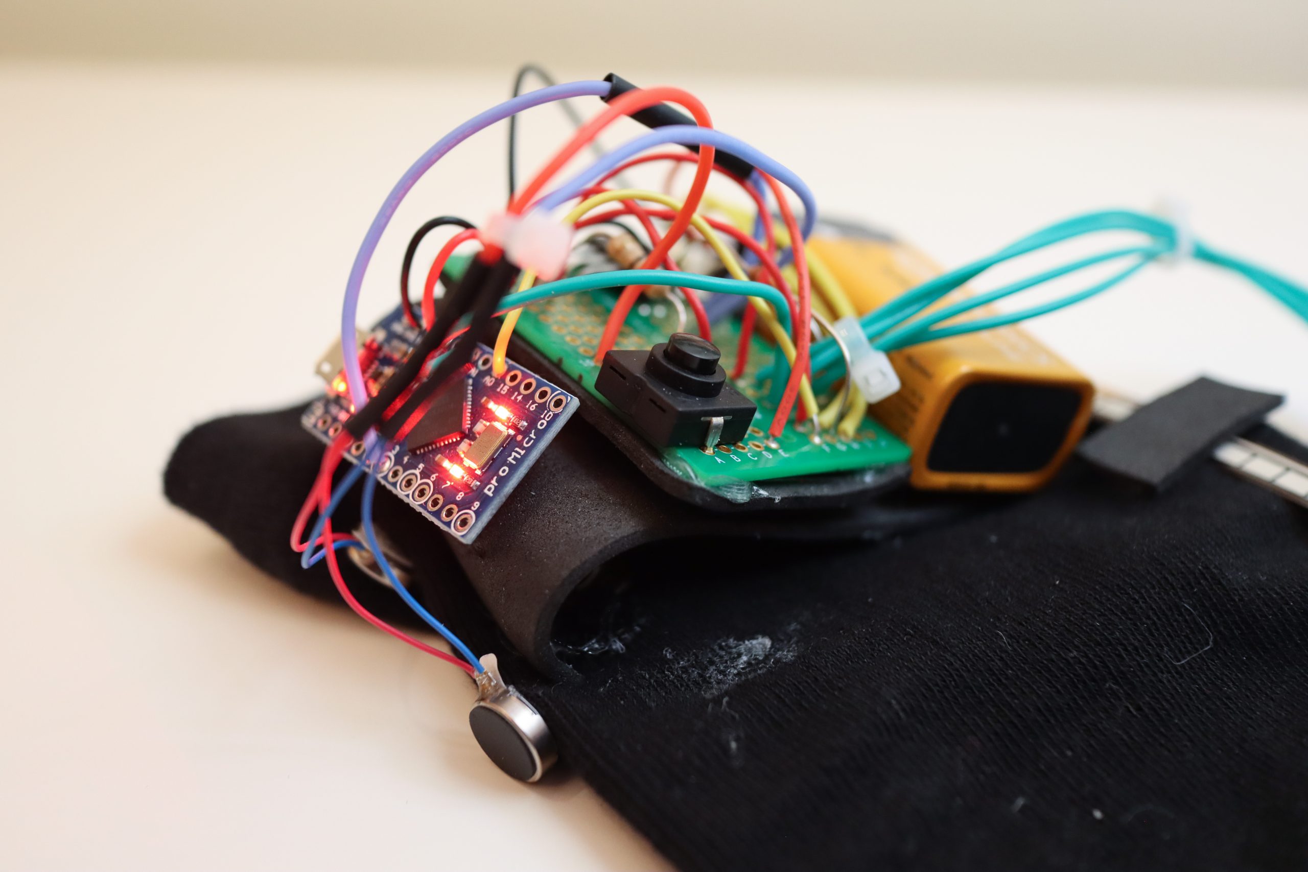
Closeup of electronics and shoddy hot-gluing and sowing.
Process
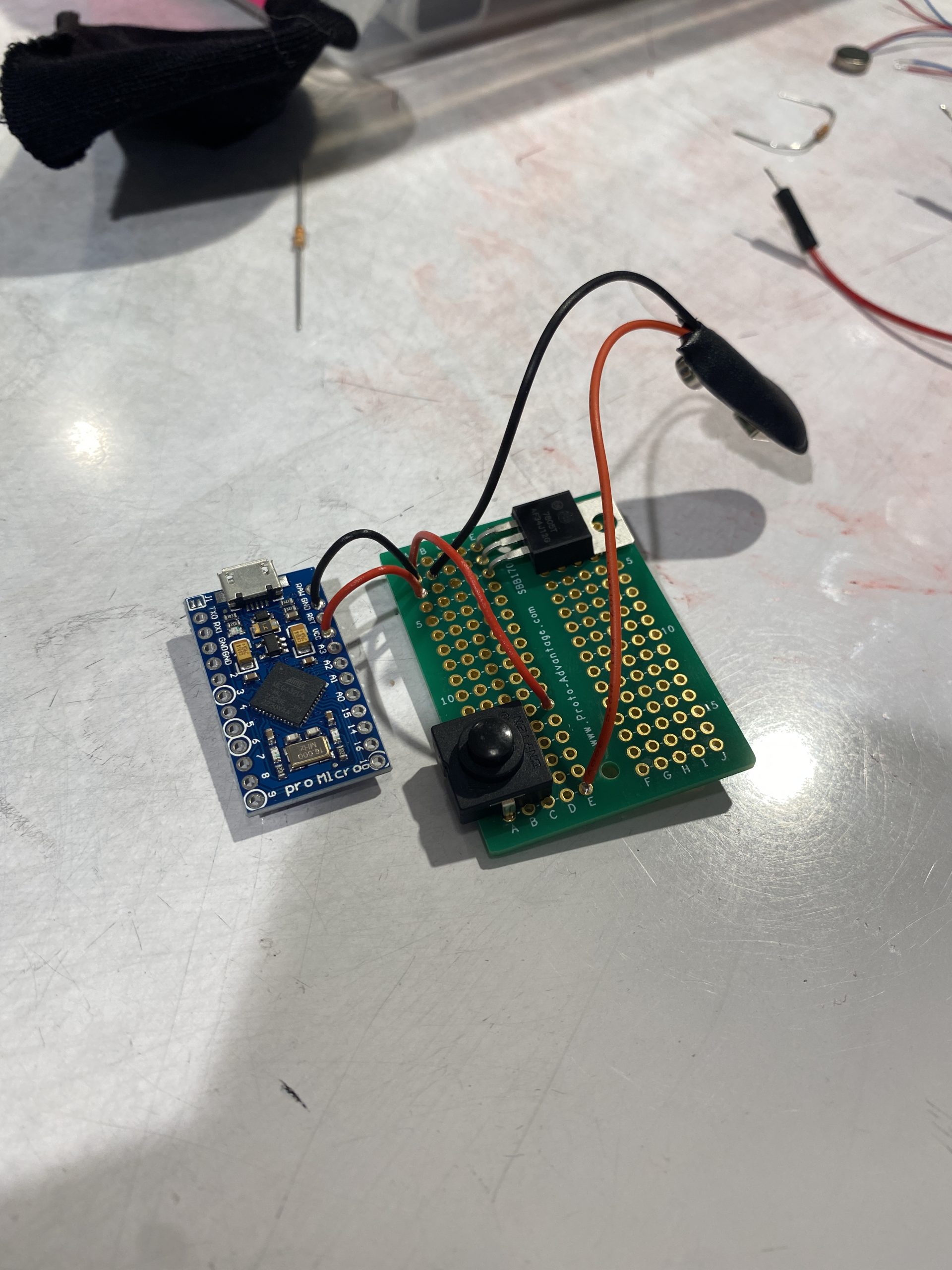
I started by picking out some components and wiring them on a breadboard to get an idea of what I’ll be using and how they work, as well as the code needed to run it.
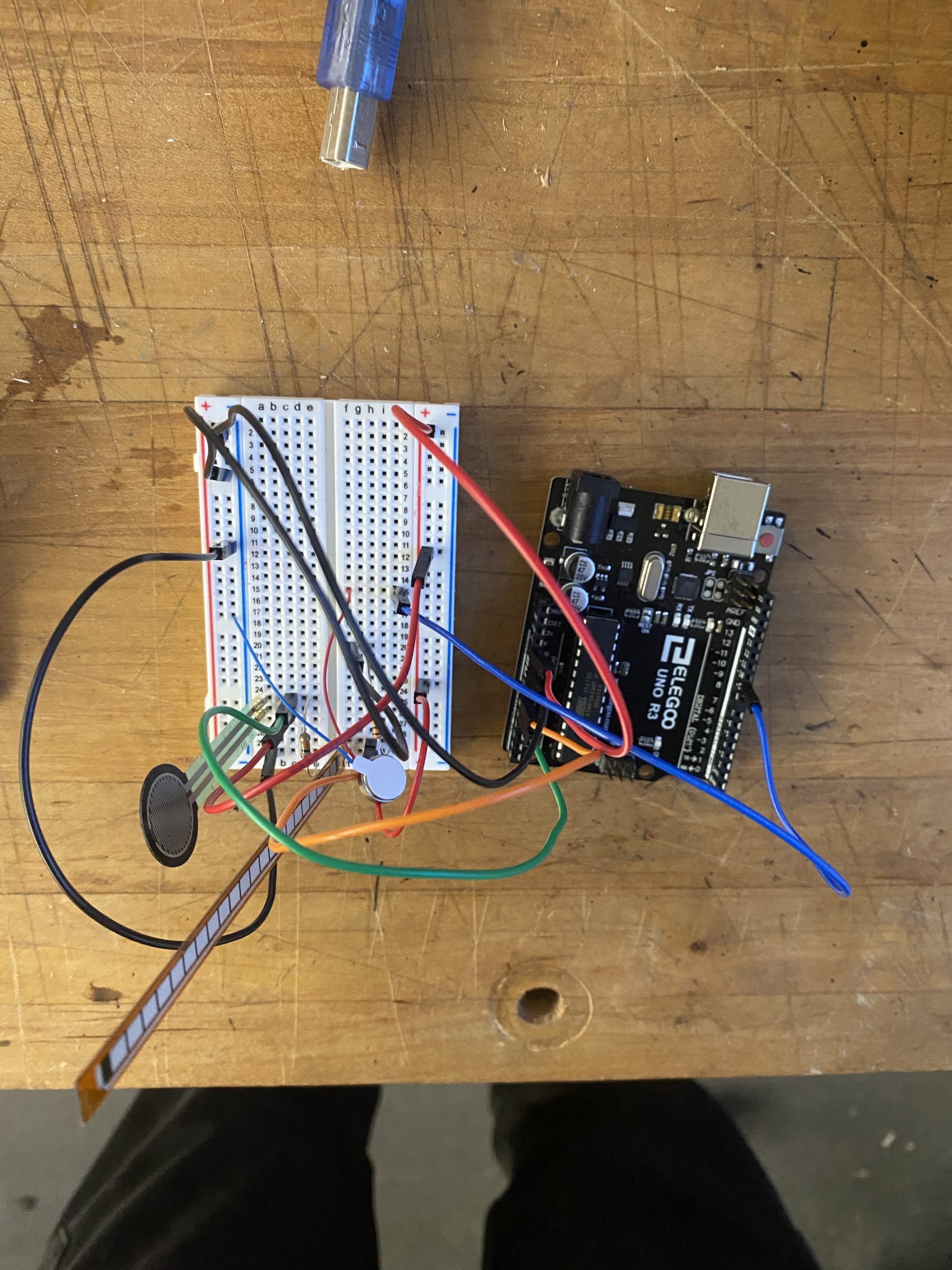
First attempt getting a pancake vibration motor to respond to a flex sensor and pressure sensor.
After getting an idea of the components I’ll be using, I taped the flex sensor underneath my elbow as a proof-of-concept prototype. It worked surprisingly well! Next up is trying to fit it all on an elbow sleeve.
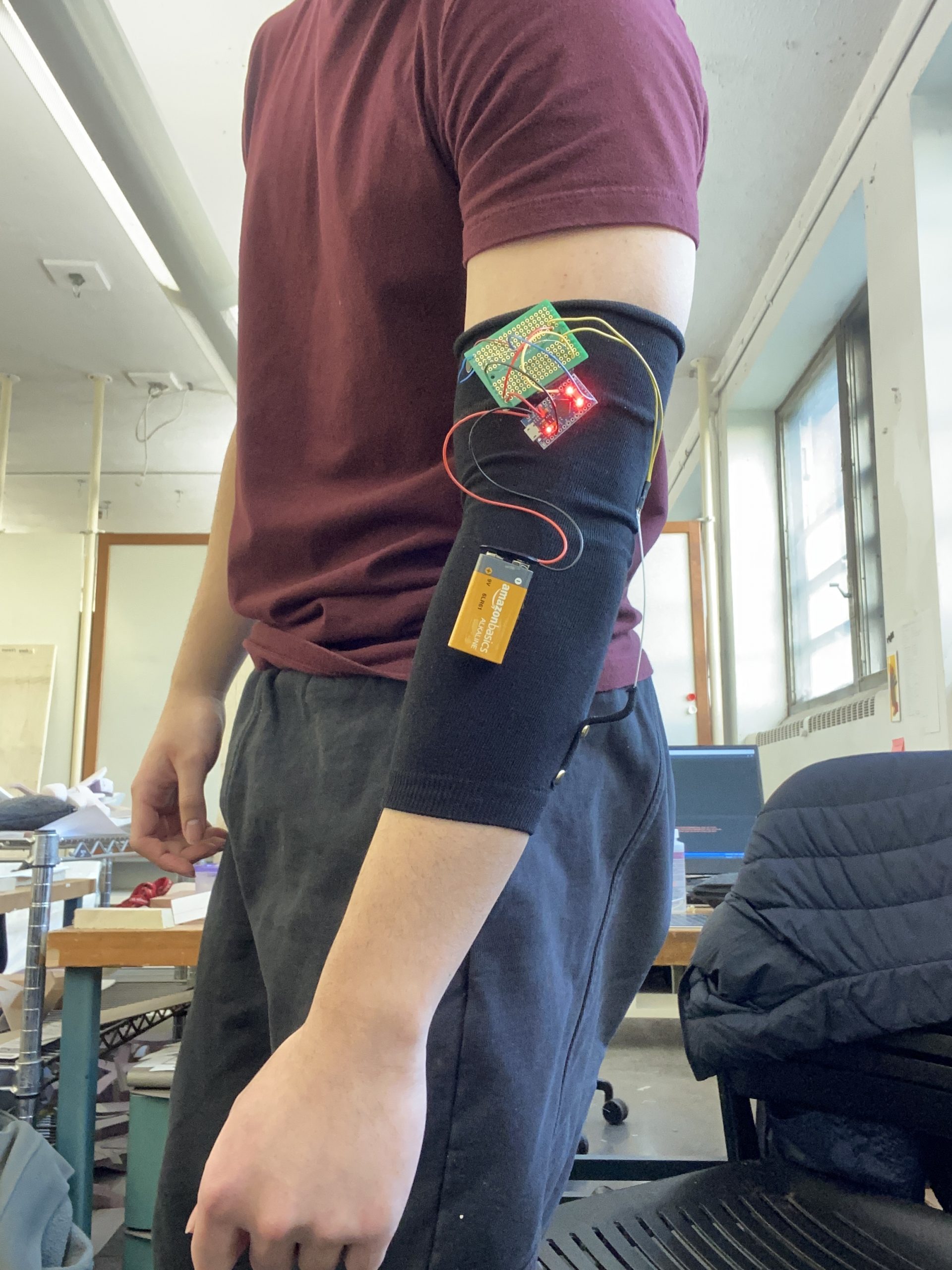
First attempt at fitting a pancake vibration motor, flex sensor, battery and Arduino Pro Micro on an elbow sleeve.
Everything works as expected – the motor vibrates when the elbow is bent past 90 degrees – but its still lacking the pressure sensor. Also, the wiring is very un-robust. The Arduino Pro Micro and pancake vibration motors are connected directly to the 9V battery. From here I worked on the hardware to make sure its safe and reliable.
Wiring the battery to a latch switch and voltage regulator.
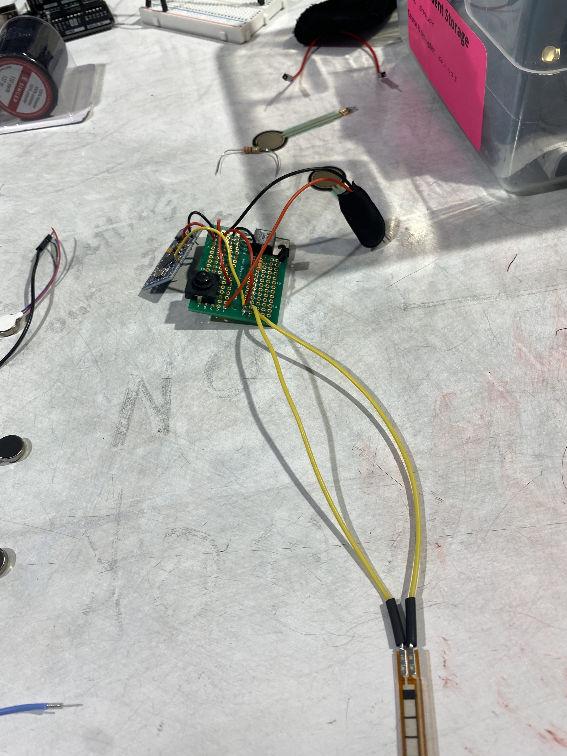
I used silicon cables to wire up the flex sensor as to not hinder any movement of the joints.
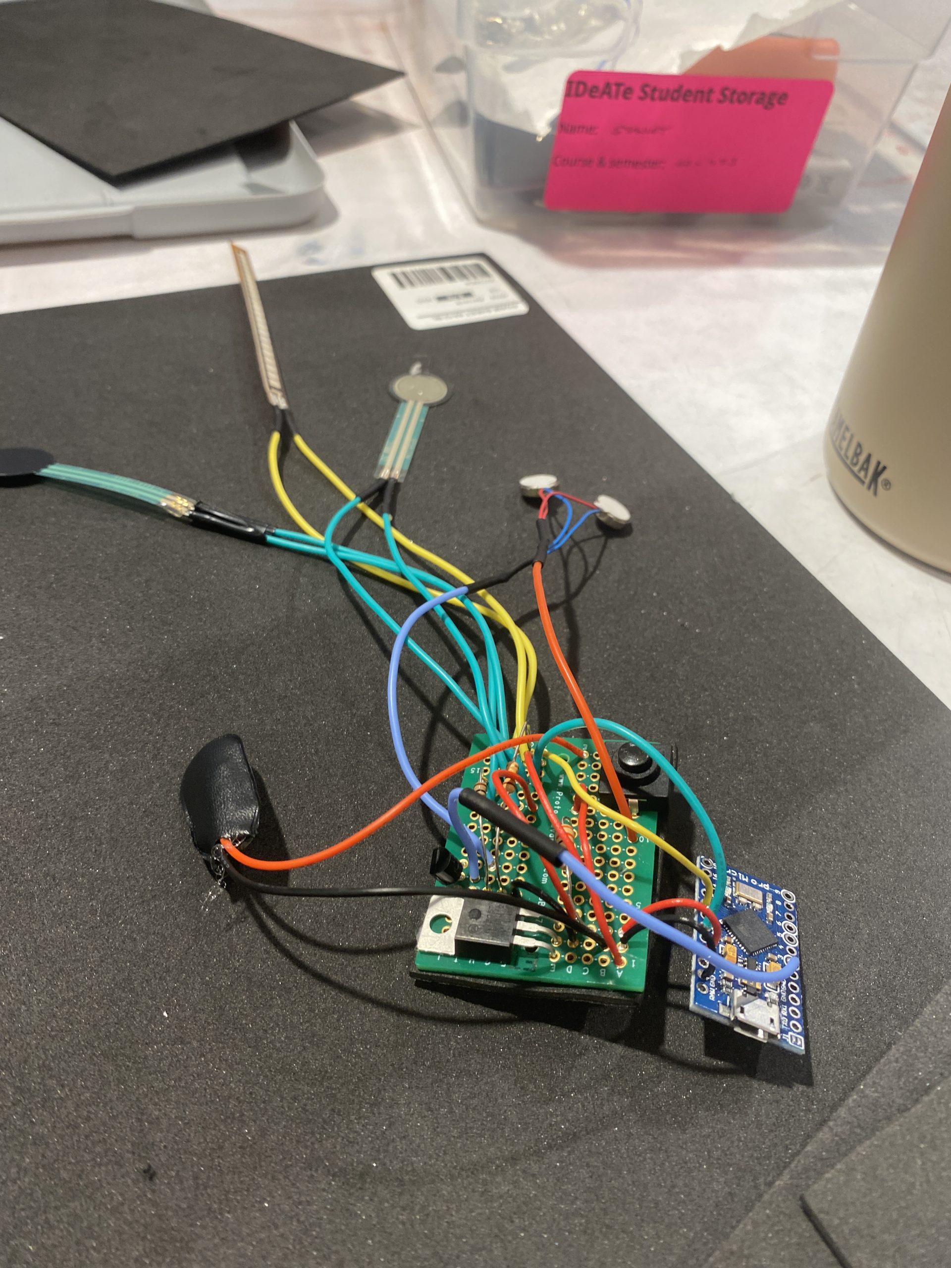
Pancake vibration motors and pressure sensors wired up. Pancake vibration motors connected to an N-channel MOSFET.
With the hardware working, I started attaching the hardware to the elbow sleeve with Velcro, shoddy sowing and hot-glue. Since the flex sensor itself can’t stretch and compress, it was most difficult trying to fix the flex sensor to the sleeve in a way that allows it to travel when the elbow is bent, but not so fixed that the sensor flexes outwards when the arm is straightened.
The flex sensor bends outwards when the arm is straightened, if there isn’t any tension pulling the strip upwards or downwards.
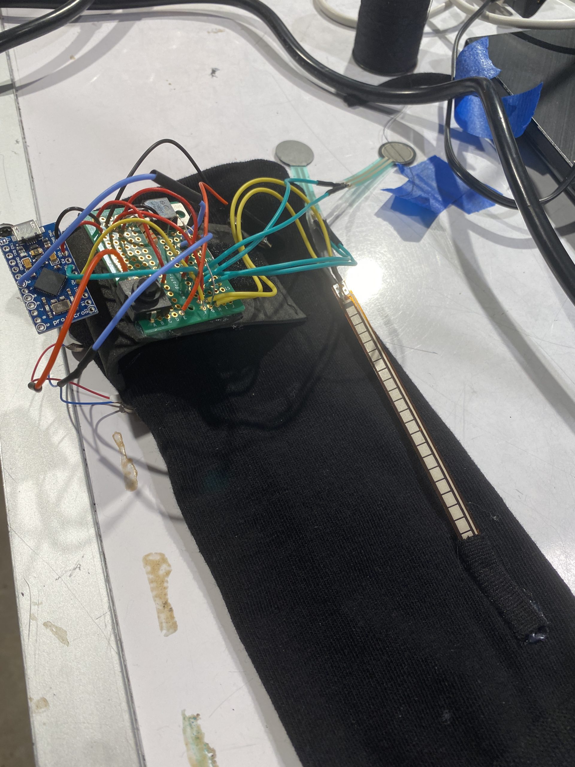
Closeup of everything secured to the elbow sleeve.
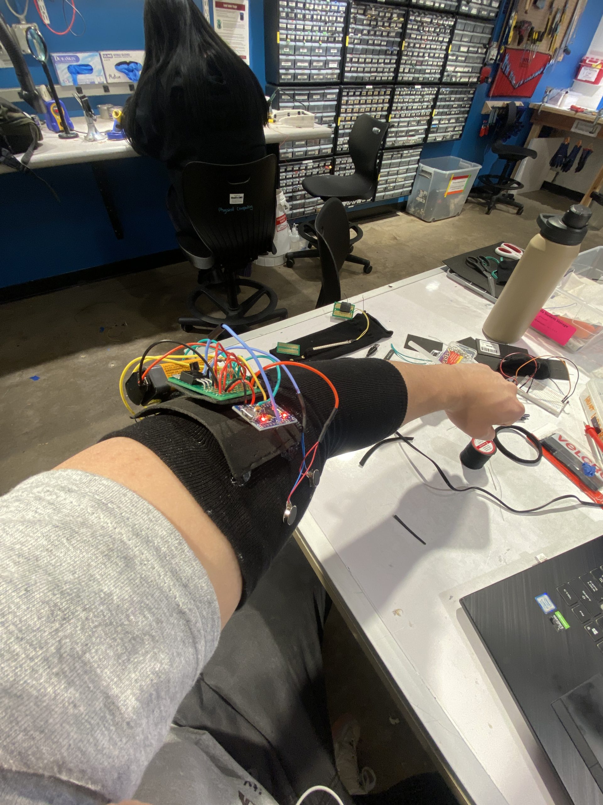
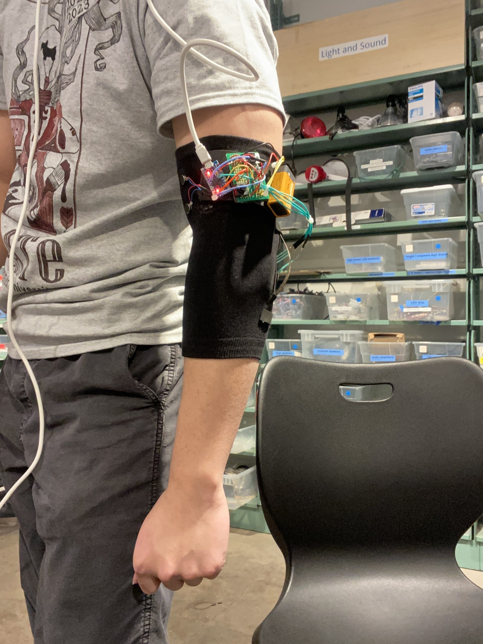
First-person view of elbow sleeve with components attached.
Discussion
Looking at the responses from my classmate, it’s clear that my solution would work better if it looked better – and I agree. That would turn the solution from something that works to something someone would actually want to use everyday, as one of my classmates put it. In its current state, all the electronics are exposed and haphazardly attached to the sleeve, which renders the whole thing useless as soon as it gets cold and someone has to put on a jacket, or when it just rains a little. The reason why my final product looks this way is because of timeframe and my inexperience with fabrics. Early on in the project, I was very interested in the types of fabrics I could use, especially ones that were used in existing compression elbow sleeves. They seemed to have a good balance of stiffness and elasticity, such that I could reasonably create a pouch to house the electronics. It was also mentioned that to improve the solution, there should be some indication as to how the sleeve should be worn, which was a very valuable piece of critique I hadn’t addressed. For the flex sensor and pressure sensors to work accurately, the flex sensor has to be centered over the elbow joint, but there aren’t any affordances or even instructions that lead to this consideration. I can think of some ways to implement this off the top of my head – like cutting a hole at the ‘hinge’ of the elbow sleeve so that there’s a more apparent top-side and bottom-side, or using an accelerometer and the pancake vibration motors to help the user position the arm sleeve correctly? I’m not sure what would work to be honest.
All-in-all, I’m still quite happy with how the final product turned out, because it works reliably and consistently (if worn right of course). It’s wearable, it detects when you’ve bent your elbow past 90 degrees for too long, it detects if you’re putting too much pressure on your elbow, and it tells you to stop. It was most fulfilling being able to create something that responds directly to the biomechanics of the human body on a wearable device, which isn’t just pushing buttons and flipping switches. Part of the reason why I think something like this should exist in the world is because elbow braces designed to prevent ulnar entrapment are intentionally stiff, to make it physically harder for you to bend your elbow for prolonged periods of time – but I wanted there to be a sleeve that still allowed freedom of movement, and I think my final product achieved that goal to a degree. I was able to practice some simple soldering and learn about building robust circuits. Though building the circuit was very simple on the breadboard, I spent a lot of time planning out my soldered breadboard, working around including components to improve the robustness of the circuit, and the placement of wires and resistors so I can see what I’m doing myself. I think I want to move towards building circuits that are less stuck to breadboards now, especially if I’m going to work on more wearables.
If I were to build another iteration, I think I would focus all my energy on fabrication to house the electronics. This would also mean making the hardware more low-profile and resistant to deformation – to bring the product to something more close to a ‘living’ piece of fabric? And less of hardware tacked onto fabric. I think this would mean using stiffer and thicker fabrics and foams, and soldering closer to the breadboard so that the overall height of the hardware can be brought down. As for the battery, I’m not sure what I’d do without the 9V battery. It just makes sense to charge and replace the battery. Or I guess coin batteries wired in series could work too.
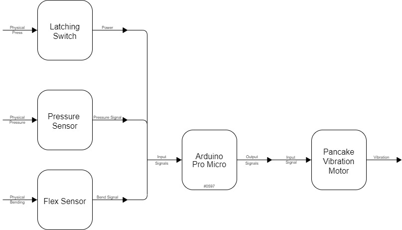
Block Diagram
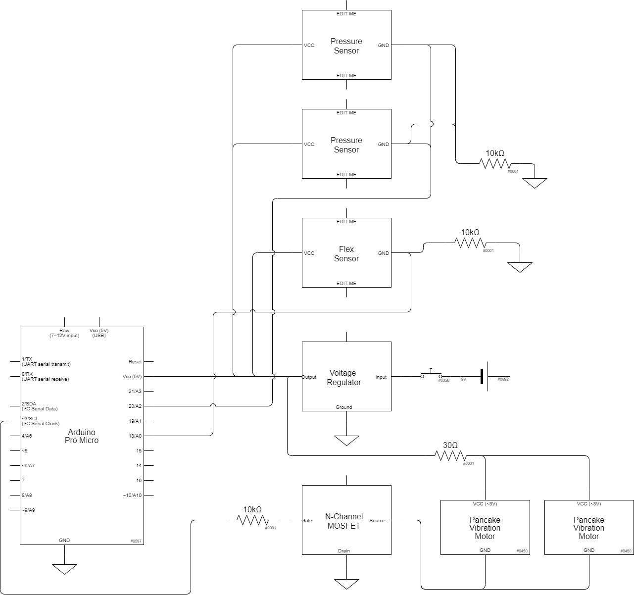
Circuit Diagram
Code
const int flexPin = A0;
const float VCC = 5;
const float R_DIV = 10000.0;
const float flatResistance = 10000.0;
const float bendResistance = 30000.0;

const int vibrPin = 3;
const int pressurePin = A2;

int bentTimer = 0;

// flex sensor code from: https://www.instructables.com/How-to-use-a-Flex-Sensor-Arduino-Tutorial/

void setup(){
  Serial.begin(9600);
  pinMode(flexPin, INPUT);
  pinMode(vibrPin, OUTPUT);
  pinMode(pressurePin, INPUT);

// turn on sequence

  digitalWrite(vibrPin, HIGH);
  delay(300);
  digitalWrite(vibrPin, LOW);
  delay(300);
  digitalWrite(vibrPin, HIGH);
  delay(300);
  digitalWrite(vibrPin, LOW);
  delay(300);
  digitalWrite(vibrPin, HIGH);
  delay(300);
  digitalWrite(vibrPin, LOW);

}

void loop(){
  int flexNum = analogRead(flexPin);
  int pressureNum = analogRead(pressurePin);

  float Vflex = flexNum * VCC / 1023.0;
  float Rflex = R_DIV * (VCC / Vflex - 1.0);
  Serial.println("Reistance: " + String(Rflex) + " ohms");

  float angle = map(Rflex, flatResistance, bendResistance, 0, 180.0);
  Serial.println("Bend: " + String(angle) + " degrees");
  Serial.println("Pressure: " + String(pressureNum) + " units");
  Serial.println();

// if arm is bent past 70 degrees, begin counter.

  if (angle >= 70){
    bentTimer += 1;
  } else{
    bentTimer = 0;
  }

// if counter exceeds 10 seconds, or pressure is detected, activate vibration motors.

  if (bentTimer > 50 || pressureNum > 850){
    digitalWrite(vibrPin, HIGH);
  } else{
    digitalWrite(vibrPin, LOW);
  }

  Serial.println("Timer: " + String(bentTimer) + " seconds");

  delay(200);
}