Practical considerations in fabrication
Power
The big question in this realm is usually batteries versus plug-in. Here are some considerations to help you weigh your options:
Batteries
Batteries’ capacities are measured in Amp-hours (Ah), or milliAmp-hours (mAh). A 1Ah battery can give you 1A of current continuously for an hour, or 500mA continuously for 2 hours, etc.
Rechargeable batteries tend to have lower capacities than alkaline (non-rechargeable) ones. Batteries will degrade over time and lose capacity, requiring replacement, and will suffer significant power loss at cold temperatures. Some rechargeables must be fully drained before charging, or they’ll suffer a “memory” problem where they lose a lot of capacity; other rechargeables should not be fully drained or they’ll be damaged. These different qualities (and others) are functions of the particular chemistry used in the battery.
Battery types:
 Lithium-ion: many different sizes/capacities available, rechargeable via USB port using this $15 Adafruit board; that same Adafruit board will give you a 5V output though the battery attached to it is not a 5V. Available capacities are 150mAh (little!) through 6,600mAh and bigger. Improperly charged lithium batteries can swell physically and even explode!
 and released under CC BY-SA 3.0](/60-223/s2026/images/D-AA-AAA.jpg "AA, AAA, and D batteries, modified from user \"Lead holder\"'s [original image at Wikimedia Commons](https://commons.wikimedia.org/wiki/File:Batteries_comparison_4,5_D_C_AA_AAA_AAAA_A23_9V_CR2032_LR44_matchstick-1.jpeg) and released under CC BY-SA 3.0") AA, AAA, D batteries: rechargeable versions of all these exist, and holders that give you different voltage outputs by stacking up different numbers of cells. Rechargeable AA, AAA, and D cells are rated at 1.2V; they differ in their physical size and power capacity. Small AAA cells hold ~1,000mAh, while big D cells hold ~5,000 mAh.
AA, AAA, D batteries: rechargeable versions of all these exist, and holders that give you different voltage outputs by stacking up different numbers of cells. Rechargeable AA, AAA, and D cells are rated at 1.2V; they differ in their physical size and power capacity. Small AAA cells hold ~1,000mAh, while big D cells hold ~5,000 mAh.
 A rechargeable USB “power bank” is also another option. This $25 one, for instance, claims to provide 10,000mAh, i.e. 10Ah, at 5V.
Plug-in
Usually the better choice for permanent installations. No need to worry about changing out or recharging the battery!
 Any device with a powered USB port (the type which would charge a phone, etc.) is capable of powering an Arduino Uno. (When your computer is not sending data back and forth through the USB cable to the Arduino, it is behaving the same as this little plug.) You can use a simple little charger of this type to give you 5V right into the Arduino.
 You can also provide 7–12V directly to the Arduino’s barrel jack power input to run it. A simple power supply like this 9V unit is nice because it has a male barrel jack, and can be plugged in to the Arduino directly.
 Alternatively, you can add a panel-mount female barrel jack (Phys Comp part 0698) onto the enclosure of your device so that the power plug does not need to make it all the way physically to the Arduino inside the box. In this case, the 7–12V from the power supply should be plugged into the Arduino’s
 VIN pin, and the ground or negative power supply line to the Arduino’s GND pin. Be sure to use a multimeter to check which pin coming out of the barrel jack is positive and which is negative before you wire it up!
In any case, it’s usually a good idea to have a power switch
The user can switch power on and off to save energy or reset the Arduino as needed.
 An easy choice for this switch is a simple rocker switch with I/0 markings on it, like this one (Phys Comp part number 0222). This sort of switch is legible to most users as a power switch, and also has clear indications so it’s obvious which way it’s switched. (Cut a rectangular hole in an enclosure wall to insert this panel-mounted switch.)
Voltages can be traded up and down as needed
⚠ Be careful to keep different voltages separated! If you attach a wire from 12V to 5V, that is akin to attaching a wire from 5V to ground: it’s a short circuit and will cause lots of current to try to flow from 12V to 5V. Mark your different voltages carefully and keep them separated physically and electrically.
 A voltage regulator is a device that can turn one voltage into another: for instance, 9V into 5V (the LM7805 (Phys Comp part 7805) will do that particular transformation). These parts will get warm if you are passing higher currents through them, so they may require heatsinking. This particular part can take an input voltage in the range of 7–25V and give 5V out.
 There is a family of voltage regulators, often called DC–DC transformers, which can “step-up” or “step-down” voltages, i.e. turn 3.7V into 5V, or 12V into 9V, etc. Again, with these, a relevant question is “how much current needs to be transformed?” If it’s a lot (more than ~2A) consider using multiple voltage sources that give you the voltages you need directly, instead of using regulators. For some examples of DC–DC converters, see Phys Comp part 0834 (steps up a lower voltage to 5V), part 0850 (steps down a higher voltage to 5V), and 0846 (an adjustable regulator, which can step a lower voltage to any output voltage between 4V and 25V).
Fabrication
There are many, many “tricks of the trade” that tinkerers, engineers, and builders have discovered over thousands of years of building things. A few pieces of advice especially relevant to the sort of work we do in Intro to Physical Computing are presented here, but these really form only the tip of the tip of the iceberg.
Soldering is strongly preferred over breadboarding!
Breadboards are great for throwing things together. They are not well-suited for long-term installations. Wires get pulled out or jiggle loose, contacts corrode, etc.
 Instead, after you breadboard everything to confirm the electronics are all correct and working, transfer your design to a board with soldered connections. This is made especially easy if you use one of our protoboards that match a medium breadboard (Phys Comp part 0034)
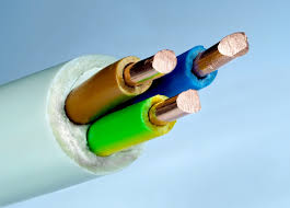 Solid core wires (like Phys Comp parts 2076, 2078, 2080, 2082) will hold a position they are bent into. They will break if bent back and forth repeatedly.
 Stranded wires (like Phys Comp parts 2086, 2087, and 2089) are made of many small wires twisted together. They will withstand many cycles of bending back and forth without breaking. They don’t hold a form when flexed, and will tend to return to a neutral straightish orientation.
In all cases, care must be taken that wires, and their connections, will not be pulled on, torqued much, crushed, or bent at a tight radius during the regular course of the project being used. “Strain relief” is the art and science of protecting wires and connectors from undue force, and if you want your creations to have reasonable longevity, you’ll be careful about it!
When wires are traveling through an enclosure wall, there are two approaches:
 Option one: keep the cable(s) intact all the way through the wall. A panel-mount “cable gland” (weird name; also called a “cord grip”) mounts into a panel and holds a cable firmly but without damaging it. The unbroken wire passes all the way through, from the outside to the inside of the enclosure. When the cable gland is tightened, it will hug the walls of the wire and seal out moisture/air from passing into the enclosure.
 Option two: use a panel-mount connector which can be plugged and unplugged. Phys Comp part 0693, for instance, allows up to 8 wires to be made into a connector. The connector has a panel mount side (pictured on the right here), which is affixed to the enclosure. This mates with a cord-end side (pictured on the left), which screws on to your cables.
Custom Cables
Custom cables are an important tool when you need connect sensors/buttons/lights/motors mounted around your project to a central protoboard. The locking connectors in the lab allow you to make cables that only plug in with the correct orientation and lock to prevent accidental removal. Think of them as connections that are almost as robust as soldering, but also allow you to disconnect them.
When you can disconnect various components from your main board, you are able to simplify assembly since each component can be mounted independently and then plugged in (this is especially helpful if you have some buttons that panel mount from the outside in, as well as others that mount from the inside out. Now you don’t have to deal with soldering wires through a hole in your enclosure). The disconnects also allow you to replace individual components without having to cut and re-solder wires. This is handy if something breaks, but also if you decide you want to use a button/sensor with a different form feel/function.
There are numerous different connector systems out in the world. Each has it’s own features, current ratings, advantages, disadvantages, gripes, tools, etc. To keep things simple, we have a limited selection Molex SL parts that should cover most of the usecases we’ll face
Crimps
At the heart of every custom cable are crimps. These are small metal parts that we can mechanically and electrically connect to a wire and then secure in a connector housing. “Crimping” a cable can be a finnecky process, but once you have it down, it isn’t very burdonsome.
These are the Molex SL crimps. They come in both “pins” and “sockets” (or “male” and “female”). Even though the ends are different, the part that attaches to the wire is the same.


To connect the crimp to the wire, we need to make both an electrical and mechanical connection. We’ll make these separately, but using the same tool. Each of the sets of wings on the backside of the crimp are used for one of these connections:

Cable Pin Counts
When you’re making a custom cable, you first need to determine how many pins you need. Essentially, how many jumper wires do you want to replace with a single cable. In the lab, we stock 3 different pin counts:
| Pin Count | Example Uses |
|---|---|
| 2 | Input power from a supply, power to a motor/output, button/switch connections |
| 3 | Servo motor connection, potentiometer connection |
| 4 | I2C sensor cable (Data, Clk, Gnd, Power) |
Connector Types
For every pin count there are 3 main connector types stocked in the lab:
| Type | Image | Use |
|---|---|---|
| Socket housing |  |
This is the most common connector. It holds sockets (similar to the sockets on your arduino Uno). It can connect to both pin housings and shrouded headers. |
| Pin Housing |  |
This holds pins (the pointy ones) and can only be connected to the socket housing. It’s useful when making extension cables where you need to connect two cables together. |
| Header (shrouded) |  |
This is similar to the header pins we usually solder to sensors/breakout boards, but this has a shroud which locks the matching socket housing in place. This is great for use with a protoboard |
Assembling the Cable
This is the crimp tool we have in the lab. Unlike others, it requires that we crimp the conductor and insulation of the wire independently.

- Strip ~3mm of insulation from the end of the wire (this is shorter than you think!). NOTE! You can only use crimps with stranded wire. Solid core wire does NOT work for crimps.
- Place the wire into the crimp so the stripped section aligns with the conductor crimp wings. The insulation crimp wings should be on either side of insulation and not bare wire!
- Using the smallest die on the crimper, compress the conductor crimp wings (you will need to squeeze the handles firmly). Give the crimp a light tug. It should be a strong enough connection to hold the crimp to the wire, even though we still need to make the true mechanical conection.
- Using the second smallest die on the crimper, compress the insulation crimp wings.
- Verify the wire/crimp connection looks good. There is no insulation under the conductor wings, there is insulation under the insulation wings, there aren’t any stray strands of wire outside the crimp, etc. It should look like:

- WIth the small retaining pin facing the side of the connector housing with square holes in the face, slide the crimp in until you hear a small click.
This one page guide from molex to crimping SL connectors uses a different tool than we have, but still has a great section on inspecting for a proper crimp.
Other Notes
After you have attached one connector, it’s good practice to hold the individual conductors together in some way. Occasionally, you will use jacketed cable where there is already a cable jacket holding the conductors together, but sometimes you need to do something yourself. One option is to twist the conductors together. This is best for longer cables. You can put all the individual wires into the chuck of a drill and spin them until they are tightly wound and hold their twist for the most part. Another option is to braid the conductors. If you have 2+ conductors you can hold the first connector in a vice/clamp and then braid the conductors before adding the second connector.
If the user should be able to open the box, don’t glue it shut
If you’ll ever want to get inside your enclosure, use a hinge or similar so that a door can be opened.
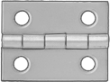 For a mechanical hinge: see suppliers on the useful links page for some choices; McMaster is an excellent source because they have a huge catalog and very well-organized search.
 You may also want a surface to be foldable or flexable using a “living hinge.” This refers to the technique of making lots of small cuts in a plane (typically done with a laser) which will allow it to flex.
A note on polish/finish
Consider the level of polish/finish you’re aiming for. You do not necessarily need to make a beautiful object—but if you have the time, thinking carefully about aesthetic concerns, and producing a handsome final piece will often greatly enhance the user’s experience of interaction with it.
Materials speak loudly. Consider a surface of your product finished with three different materials:
- A piece of varnished wood with exposed grain shows how it grew, and later, how it was cut from the tree; it will communicate warmth and tangibility, as well as referring to the craft of past generations.
- A piece of polished aluminum in the same place has another valence altogether: it may read like a part of a machine from the nineteenth century, or perhaps a reference to midcentury design trends of the 1950s and 60s.
- A piece of grey 3D-printed plastic will read totally differently for most users: it will communicate cutting-edge fabrication methods—or perhaps twenty-first century plastic consumerism.
Whatever your material choices are, know that they are choices. Even if you default to the easiest, cheapest, or simplest fabrication method available, your visual choices will be part of your users’ interpretation of your final creation. Be purposeful and cognizant of these decisions!
