Warp Field is an interactive experience for one person and a modular synthesizer, through the medium of a pair of scissors and a sheet of paper. Designed as an act of exploration, the performer sits with the paper in a private space and cuts the paper at their own pace, exploring the effects their choices make on the sounds created by the synthesizer. The performer knows that they must begin the experience by cutting from one end of the paper to the other, but is free to cut however they want in the spaces in between.
The way sounds reacts might not exactly be clear at first, but the more the performer cuts, the more they learn. Instead of a blank piece of paper, the sheet is decorated with stars and galaxies, likening the cut of the scissors to a spacecraft gaining knowledge from exploring the vast unknown. This is the meaning of the title Warp Field. Different areas trigger different changes in sound when cut, sometimes permanently. In this way, all actions made truly do matter. And because the paper is being destroyed in the process, these choices matter even more.
As an artist, I’ve always sought out ways of finding interaction that asks more of the person on the other side of the experience. Video games, for example, are successful at this, creating investment through the user’s own explorations and decisions. Instead of a passive experience, the relationship between art and audience is turned into an active one. Without someone to interact with it, the art wouldn’t exist. My goal with this, as with some other past works, is to find a way to take the this kind of relationship and applying it to music, blurring the lines between performer, audience, and composer.
Process Images
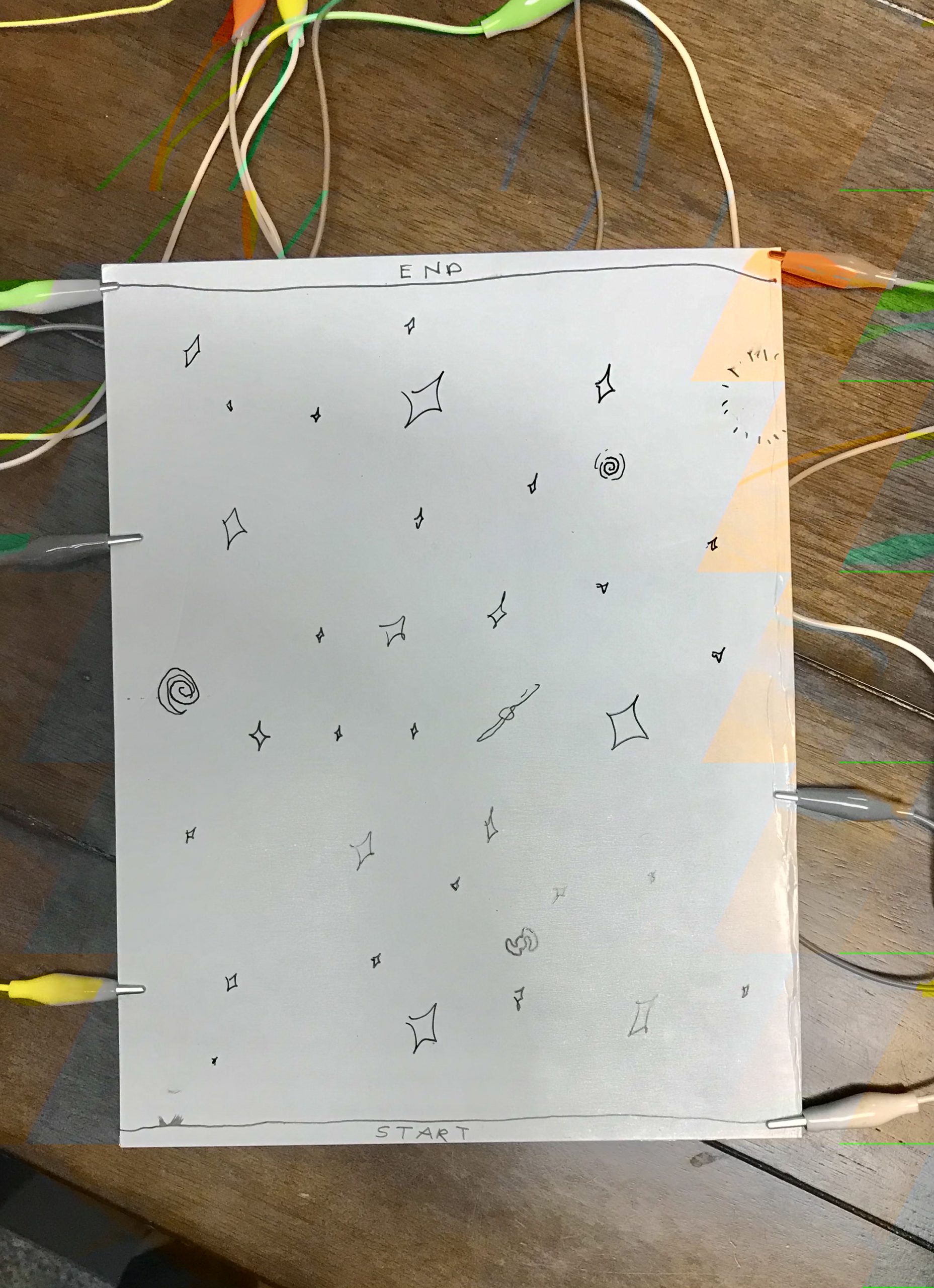
An early draft of what the sheet could have looked like. The Pen drawn paths were eventually abandoned for more free exploration.
Originally, the plan was for the signal to be transmitted through the body like so. However, this proved to not be feasible as the body introduced too much resistance.
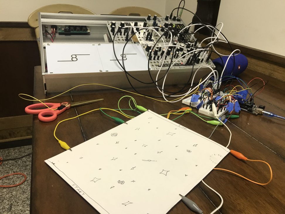
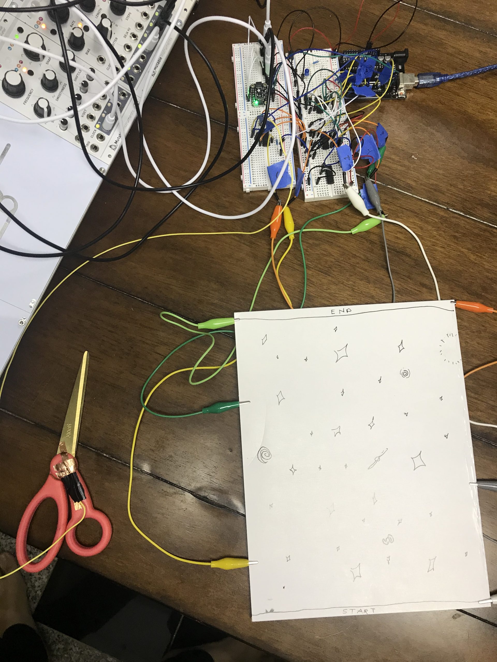
An idea of what the setup would be like. This ended up being fairly accurate. Stereo panning ended up not being used so the speakers were kept to one side in the final product.
One key decision point was in me realizing I could use my synthesizer to generate sounds in real time, as opposed to sound files like I had originally planned.
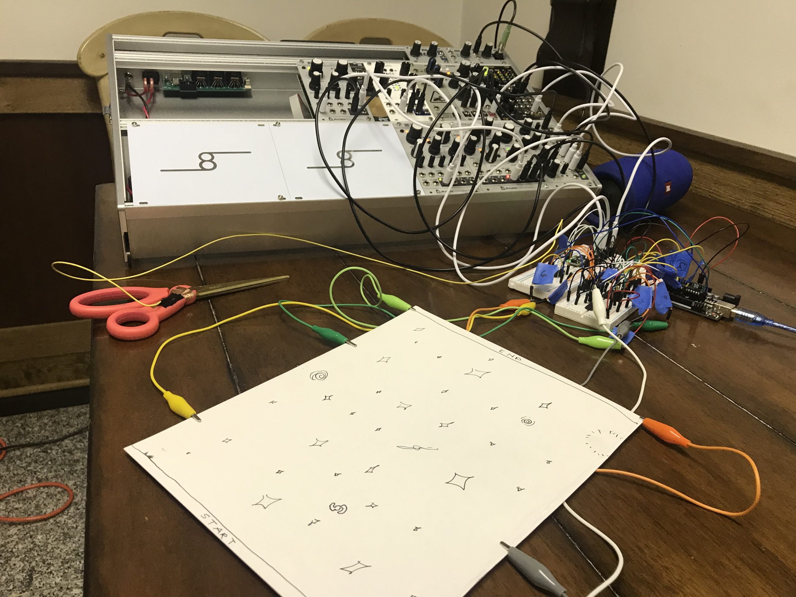
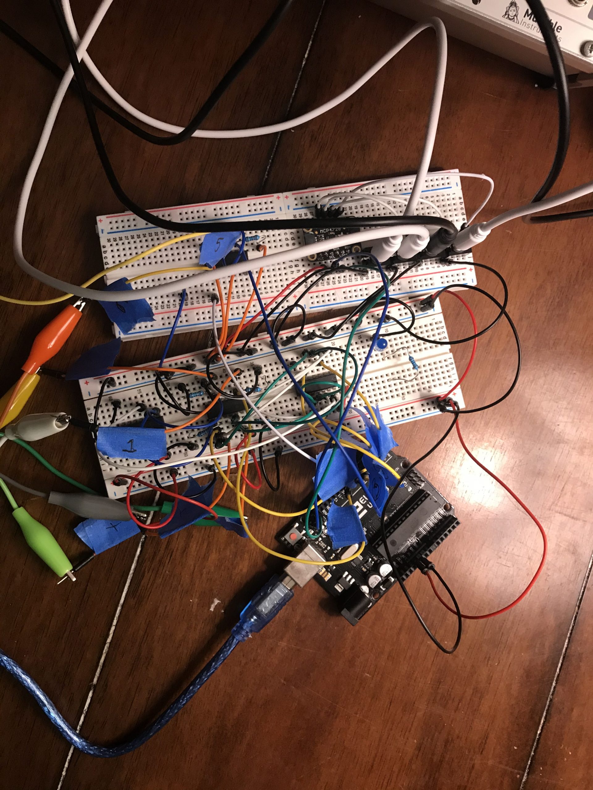
As shown in this draft image, the geometry of the circuit paths in the original idea was much more important. This also required the use of much more alligator clips going into the sheet. The final product ended up only having one power source.
Process Reflection
The easiest part of the process was probably working on the sound design at the end. That is my field of expertise – so it was easy for me to create the sounds and decide how to control that with the device I made. The hardest was definitely the circuitry aspect. I had no prior experience using logic chips, and things like Pull down resistors were confusing for me and took me many hours to figure out how to get all of logic chips working. I am definitely glad I did learn how to get them to work and build a complex circuit out of it! I definitely want to continue exploring circuitry and using the Arduino especially because I am starting to see the potential it can give me.
I think another challenge was in creating a good idea for the project itself! I spent so much energy on the original idea that I had a very strong idea of what the final project would end up looking like and how it would function. Obviously there were some changes along the way, but I hope I can continue to think up interesting ideas for the remaining projects.
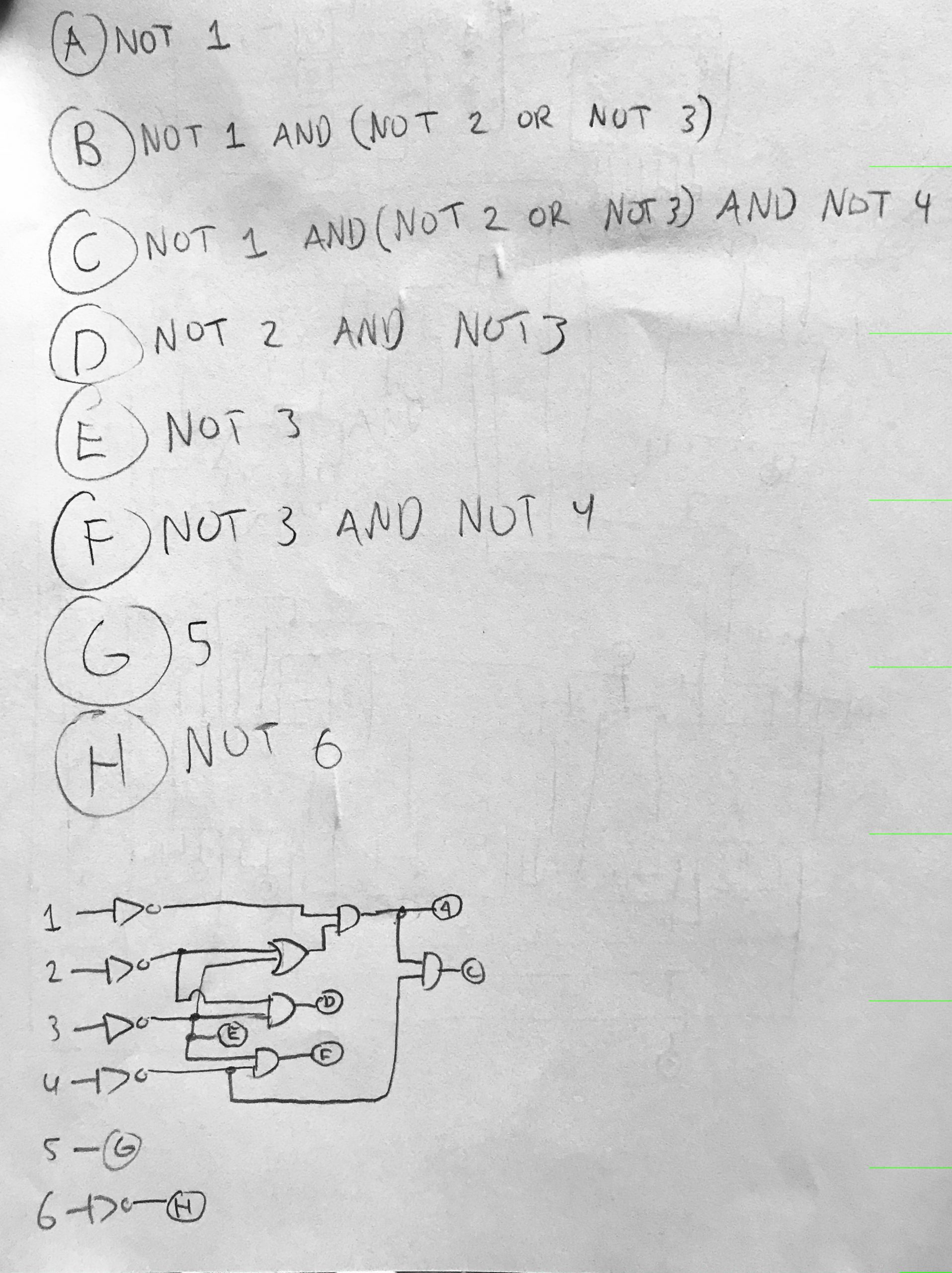
Logic Diagram
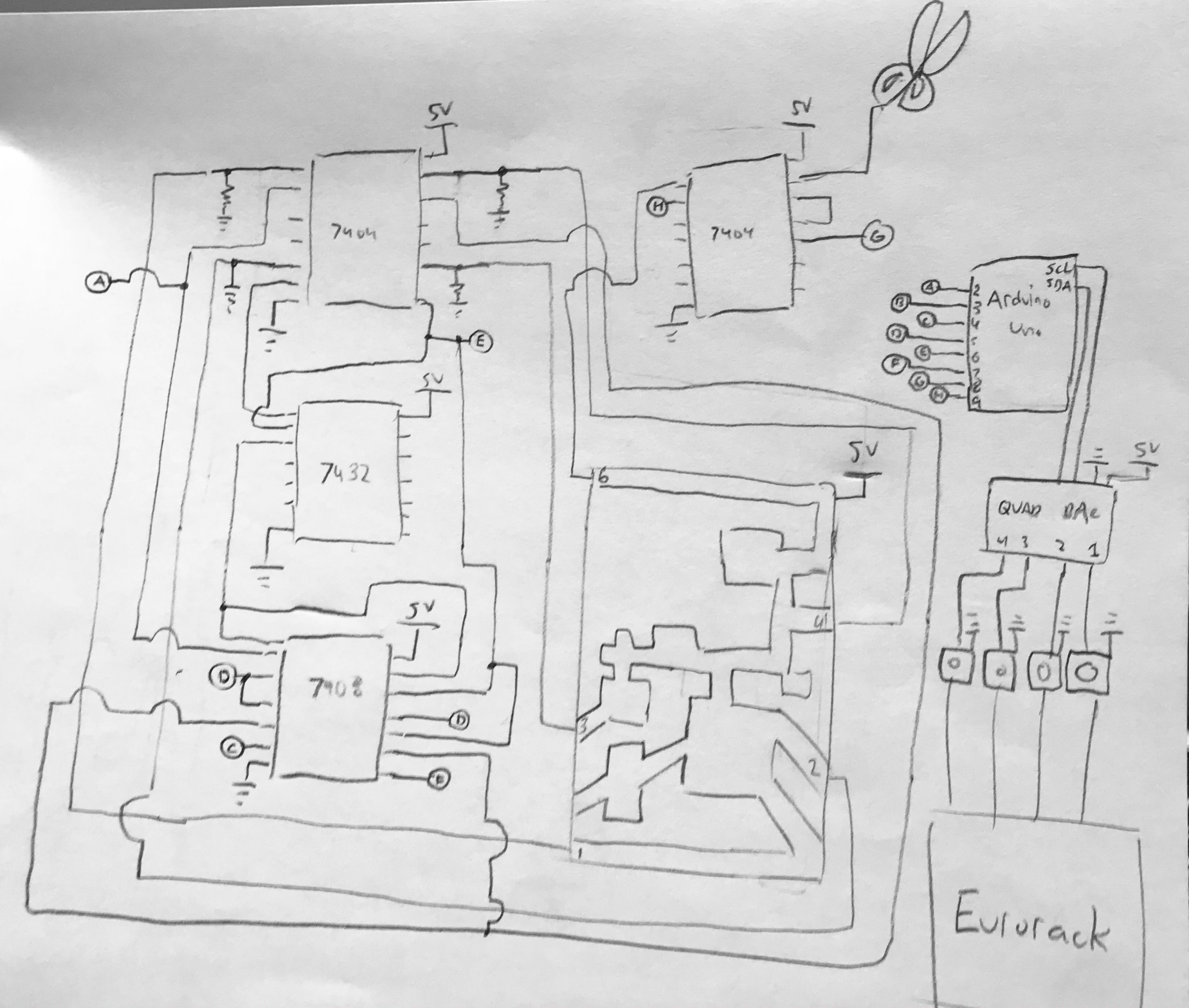
Electronic Schematic
Arduino Code
/* Warp Field
* William Lamkin
*
* This code takes inputs from the external Logic Gates and sends
* predetermined voltage values out of the 4 outputs of the
* Adafruit MCP4728 Quad DAC. These voltage signals are then
* sent into a Eurorack synthesizer to control sounds.
*/
#include <Adafruit_MCP4728.h>
#include <Wire.h>
//assign pin names
constint pinA = 9;
constint pinB = 2;
constint pinC = 3;
constint pinD = 4;
constint pinE = 5;
constint pinF = 6;
constint pinG = 7;
constint pinH = 8;
//defining variables for the values of pins
int A = 0;
int B = 0;
int C = 0;
int D = 0;
int E = 0;
int F = 0;
int G = 0;
int H = 0;
Adafruit_MCP4728 mcp;
voidsetup(){
//activating pins
pinMode(pinA, INPUT);
pinMode(pinB, INPUT);
pinMode(pinC, INPUT);
pinMode(pinD, INPUT);
pinMode(pinE, INPUT);
pinMode(pinF, INPUT);
pinMode(pinG, INPUT);
pinMode(pinH, INPUT);
// checks for I2C connection to the MCP4728 (code from Adafruit)
Serial.begin(115200);
while(!Serial)
delay(10); // will pause Zero, Leonardo, etc until serial console opens
Serial.println("Adafruit MCP4728 test!");
// Try to initialize!
if(!mcp.begin()){
Serial.println("Failed to find MCP4728 chip");
while(1){
delay(10);
}
}
//default values for the outputs
mcp.setChannelValue(MCP4728_CHANNEL_A, 0);
mcp.setChannelValue(MCP4728_CHANNEL_B, 0);
mcp.setChannelValue(MCP4728_CHANNEL_C, 0);
mcp.setChannelValue(MCP4728_CHANNEL_D, 0);
}
voidloop(){
//update pin state variables
A = digitalRead(pinA);
B = digitalRead(pinB);
C = digitalRead(pinC);
D = digitalRead(pinD);
E = digitalRead(pinE);
F = digitalRead(pinF);
G = digitalRead(pinG);
H = digitalRead(pinH);
// Had to mirror the logic of the gates in here since only one
// value can be sent to an output at a time
// Channel B controlled the lowpass filter cutoff on the drone
if(A == HIGH){
if(H == HIGH){
mcp.setChannelValue(MCP4728_CHANNEL_B, 0);
}
if(H == LOW){
if(B == LOW){
mcp.setChannelValue(MCP4728_CHANNEL_B, 1024);
}
elseif(B == HIGH){
if(C == LOW){
mcp.setChannelValue(MCP4728_CHANNEL_B, 2048);
}
elseif(C == HIGH){
mcp.setChannelValue(MCP4728_CHANNEL_B, 4095);
}
}
}
}
// Channel C controlled the amount of resonance on that filter
if(D == HIGH){
if(F == HIGH){
mcp.setChannelValue(MCP4728_CHANNEL_C, 4095);
}
elseif(F == LOW){
mcp.setChannelValue(MCP4728_CHANNEL_C, 2048);
}
}
// Channel D controlled the volume of the random pitch granular
if(E == HIGH){
if(H == HIGH){
mcp.setChannelValue(MCP4728_CHANNEL_D, 0);
}
elseif(H == LOW){
if(F == LOW){
mcp.setChannelValue(MCP4728_CHANNEL_D, 2048);
}
elseif(F == HIGH){
mcp.setChannelValue(MCP4728_CHANNEL_D, 4095);
}
}
}
// Channel A checks if the scissors are touching the circuit
if(G == HIGH){
mcp.setChannelValue(MCP4728_CHANNEL_A, 4095);
}
elseif(G == LOW){
mcp.setChannelValue(MCP4728_CHANNEL_A, 0);
}
}
/*  Warp Field
 *  William Lamkin
 *
 *  This code takes inputs from the external Logic Gates and sends
 *  predetermined voltage values out of the 4 outputs of the
 *  Adafruit MCP4728 Quad DAC. These voltage signals are then
 *  sent into a Eurorack synthesizer to control sounds.

*/

#include <Adafruit_MCP4728.h>
#include <Wire.h>

//assign pin names
const int pinA = 9;
const int pinB = 2;
const int pinC = 3;
const int pinD = 4;
const int pinE = 5;
const int pinF = 6;
const int pinG = 7;
const int pinH = 8;

//defining variables for the values of pins
int A = 0;
int B = 0;
int C = 0;
int D = 0;
int E = 0;
int F = 0;
int G = 0;
int H = 0;

Adafruit_MCP4728 mcp;

void setup() {

  //activating pins
  pinMode(pinA, INPUT);
  pinMode(pinB, INPUT);
  pinMode(pinC, INPUT);
  pinMode(pinD, INPUT);
  pinMode(pinE, INPUT);
  pinMode(pinF, INPUT);
  pinMode(pinG, INPUT);
  pinMode(pinH, INPUT);


  // checks for I2C connection to the MCP4728 (code from Adafruit)
  Serial.begin(115200);
  while (!Serial)
    delay(10); // will pause Zero, Leonardo, etc until serial console opens

  Serial.println("Adafruit MCP4728 test!");

  // Try to initialize!
  if (!mcp.begin()) {
    Serial.println("Failed to find MCP4728 chip");
    while (1) {
      delay(10);
    }

  }

  //default values for the outputs
  mcp.setChannelValue(MCP4728_CHANNEL_A, 0);
  mcp.setChannelValue(MCP4728_CHANNEL_B, 0);
  mcp.setChannelValue(MCP4728_CHANNEL_C, 0);
  mcp.setChannelValue(MCP4728_CHANNEL_D, 0);

}

void loop() {

  //update pin state variables
  A = digitalRead(pinA);
  B = digitalRead(pinB);
  C = digitalRead(pinC);
  D = digitalRead(pinD);
  E = digitalRead(pinE);
  F = digitalRead(pinF);
  G = digitalRead(pinG);
  H = digitalRead(pinH);


  // Had to mirror the logic of the gates in here since only one
  // value can be sent to an output at a time

  // Channel B controlled the lowpass filter cutoff on the drone
  if (A == HIGH) {
    if (H == HIGH) {
      mcp.setChannelValue(MCP4728_CHANNEL_B, 0);
    }
    if (H == LOW) {
       if (B == LOW) {
            mcp.setChannelValue(MCP4728_CHANNEL_B, 1024);
          }
       else if (B == HIGH) {
          if (C == LOW) {
            mcp.setChannelValue(MCP4728_CHANNEL_B, 2048);
          }
          else if (C == HIGH) {
            mcp.setChannelValue(MCP4728_CHANNEL_B, 4095);
          }
       }
    }
  }


  // Channel C controlled the amount of resonance on that filter
  if (D == HIGH) {
    if (F == HIGH) {
      mcp.setChannelValue(MCP4728_CHANNEL_C, 4095);
    }
    else if (F == LOW) {
      mcp.setChannelValue(MCP4728_CHANNEL_C, 2048);
    }

  }

  // Channel D controlled the volume of the random pitch granular
  if (E == HIGH) {
    if (H == HIGH) {
      mcp.setChannelValue(MCP4728_CHANNEL_D, 0);
    }
    else if (H == LOW) {
      if (F == LOW) {
        mcp.setChannelValue(MCP4728_CHANNEL_D, 2048);
      }
      else if (F == HIGH) {
        mcp.setChannelValue(MCP4728_CHANNEL_D, 4095);
      }
    }
  }

  // Channel A checks if the scissors are touching the circuit
  if (G == HIGH) {
    mcp.setChannelValue(MCP4728_CHANNEL_A, 4095);

  }
  else if (G == LOW) {
    mcp.setChannelValue(MCP4728_CHANNEL_A, 0);

  }


}
/* Warp Field
* William Lamkin
*
* This code takes inputs from the external Logic Gates and sends
* predetermined voltage values out of the 4 outputs of the
* Adafruit MCP4728 Quad DAC. These voltage signals are then
* sent into a Eurorack synthesizer to control sounds.
*/#include<Adafruit_MCP4728.h>#include<Wire.h>//assign pin namesconstint pinA =9;constint pinB =2;constint pinC =3;constint pinD =4;constint pinE =5;constint pinF =6;constint pinG =7;constint pinH =8;//defining variables for the values of pins int A =0;int B =0;int C =0;int D =0;int E =0;int F =0;int G =0;int H =0;Adafruit_MCP4728 mcp;void setup(){//activating pins
pinMode(pinA, INPUT);
pinMode(pinB, INPUT);
pinMode(pinC, INPUT);
pinMode(pinD, INPUT);
pinMode(pinE, INPUT);
pinMode(pinF, INPUT);
pinMode(pinG, INPUT);
pinMode(pinH, INPUT);// checks for I2C connection to the MCP4728 (code from Adafruit)Serial.begin(115200);while(!Serial)
delay(10);// will pause Zero, Leonardo, etc until serial console opensSerial.println("Adafruit MCP4728 test!");// Try to initialize!if(!mcp.begin()){Serial.println("Failed to find MCP4728 chip");while(1){
delay(10);}}//default values for the outputs
mcp.setChannelValue(MCP4728_CHANNEL_A,0);
mcp.setChannelValue(MCP4728_CHANNEL_B,0);
mcp.setChannelValue(MCP4728_CHANNEL_C,0);
mcp.setChannelValue(MCP4728_CHANNEL_D,0);}void loop(){//update pin state variables
A = digitalRead(pinA);
B = digitalRead(pinB);
C = digitalRead(pinC);
D = digitalRead(pinD);
E = digitalRead(pinE);
F = digitalRead(pinF);
G = digitalRead(pinG);
H = digitalRead(pinH);// Had to mirror the logic of the gates in here since only one// value can be sent to an output at a time// Channel B controlled the lowpass filter cutoff on the droneif(A == HIGH){if(H == HIGH){
mcp.setChannelValue(MCP4728_CHANNEL_B,0);}if(H == LOW){if(B == LOW){
mcp.setChannelValue(MCP4728_CHANNEL_B,1024);}elseif(B == HIGH){if(C == LOW){
mcp.setChannelValue(MCP4728_CHANNEL_B,2048);}elseif(C == HIGH){
mcp.setChannelValue(MCP4728_CHANNEL_B,4095);}}}}// Channel C controlled the amount of resonance on that filterif(D == HIGH){if(F == HIGH){
mcp.setChannelValue(MCP4728_CHANNEL_C,4095);}elseif(F == LOW){
mcp.setChannelValue(MCP4728_CHANNEL_C,2048);}}// Channel D controlled the volume of the random pitch granularif(E == HIGH){if(H == HIGH){
mcp.setChannelValue(MCP4728_CHANNEL_D,0);}elseif(H == LOW){if(F == LOW){
mcp.setChannelValue(MCP4728_CHANNEL_D,2048);}elseif(F == HIGH){
mcp.setChannelValue(MCP4728_CHANNEL_D,4095);}}}// Channel A checks if the scissors are touching the circuitif(G == HIGH){
mcp.setChannelValue(MCP4728_CHANNEL_A,4095);}elseif(G == LOW){
mcp.setChannelValue(MCP4728_CHANNEL_A,0);}}
Group Check-In 2: 9-30-20
By William Lamkin
Made significant progress from Monday in that I discovered how logic chips function! Got an AND gate to function with the scissors, showing its ability to be conductive, and also how that could successfully route through the human body. Video below:
I am still waiting on my Adafruit Quad DAC to come in, from which I could complete my circuit and be able to control my synthesizer, since it would allow my Arduino to send out a full range of voltages.
Process Blog Check-In 9-28-20
By William Lamkin
In reflecting on how to utilize ambient sound that adaptively changes, I’ve decided to use a modular synthesizer to generate sounds. I had toyed around with the idea of using an mp3 playing device that would work with an Arduino, but I realized that the technology involved with those wasn’t as fully interactive as I would like it to be. My goals for this project are for the actions of the user to have a significant effect on the sound.
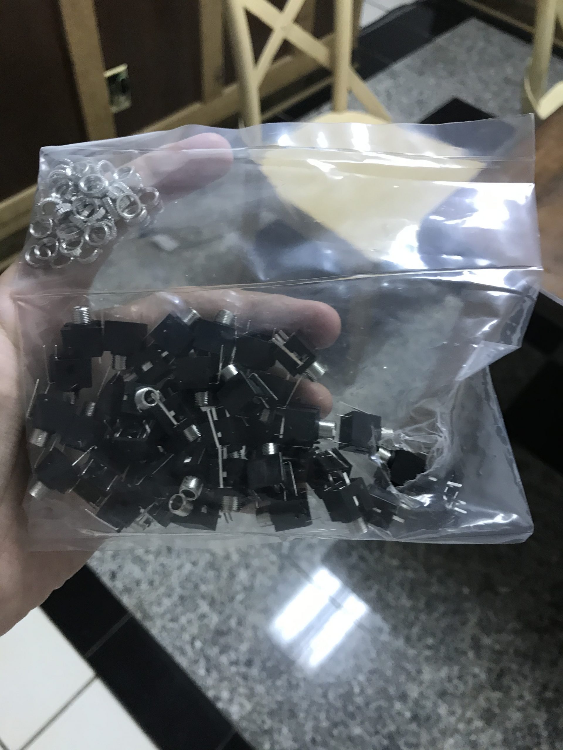
I will be using logic chips for all of connections, and these will be connected to the board to be cut via a alligator clips, and the output signals of these logic chips will then be sent into the inputs of the Arduino. The Arduino will send out voltages through an Adafruit Quad DAC which I have ordered and I will be able to connect to the synthesizer via these audio jack parts. In the link is a demo of the kinds of sounds that can be made and changed.
Here is a diagram of what I want the setup to be like! I do want it to be a dark and isolated experience so the user can focus on what they are doing. For documentation purposes, I will be recording a video of myself at home working on this.
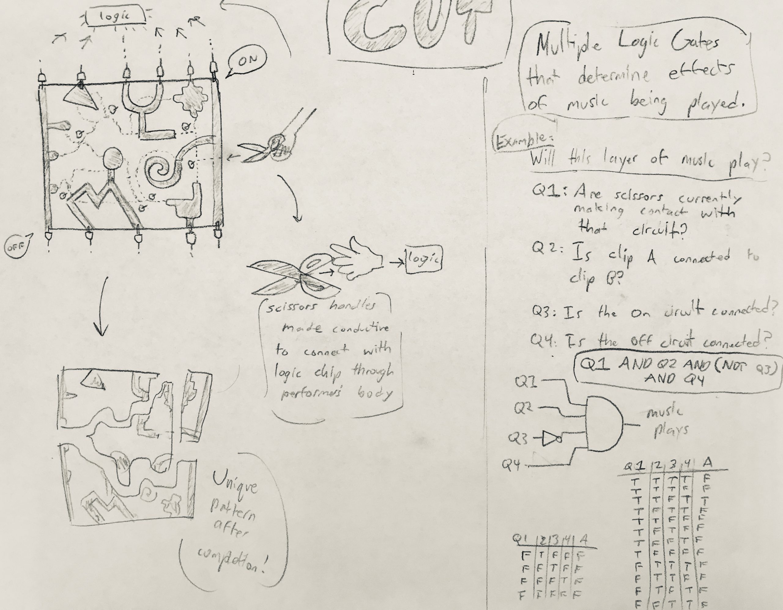
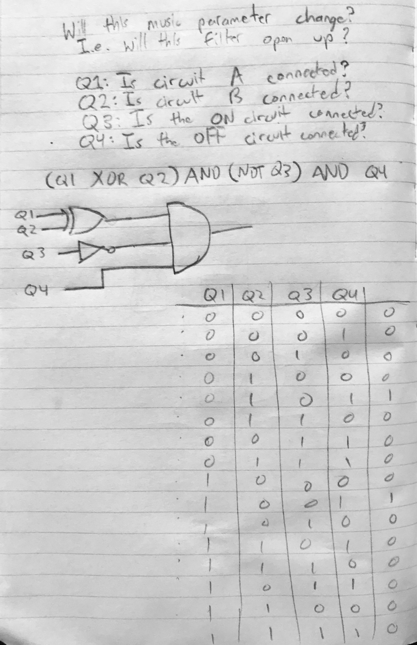
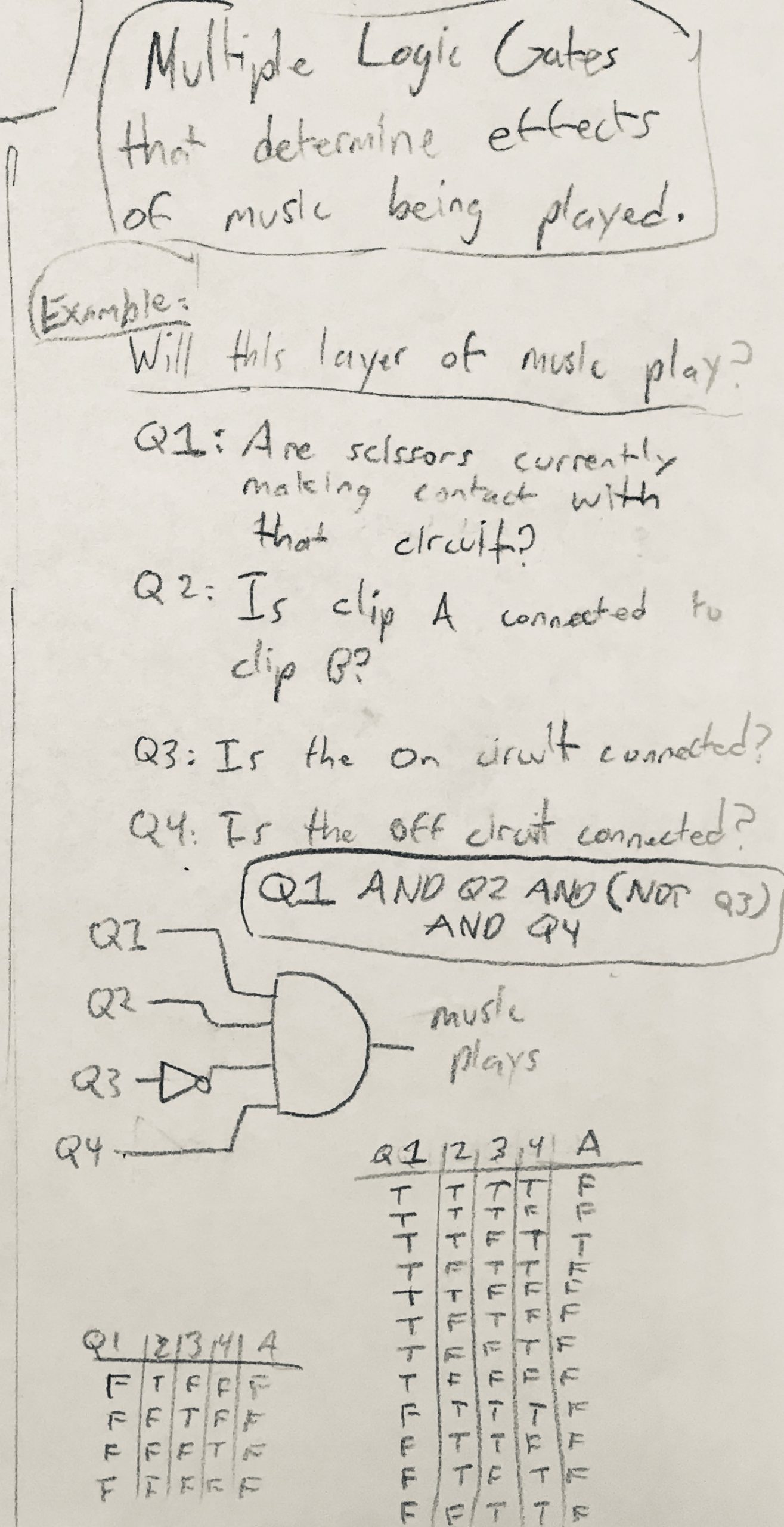
Here is an example logic problem for how a parameter of music could be changed.
In Process Critique: 9-23-20
By William Lamkin
Draft version of Cut, made using cardstock and conductive tape to create circuits. In essence, all circuits start ON (1), except one involving the scissors, and breaking them (0) triggers a reaction in ambient sound created from the experience interactively.
The side which starts the experience is labeled at the top “START”, and will be cut using specially created scissors to interact with it. Breaking the start circuit will begin the the output of music. Cutting along the dashed lines, at forks in the path, the player will be given prompts to choose a direction to go down cutting. Certain circuits are cut (turned off) to trigger an effect. Others are created through the act of cutting itself, because the scissors also have conductive tape on them that connects the blade of the scissors to the hand. The body is then used as a connection in itself to the other end of circuit. Therefore, circuits are actively created throughout the piece. Eventually the other end of the sheet is breached (labeled “END”) and this stops music playback.
Connections on scissors labeled below.
Multiple logic operations will be used through combinations of the different circuits. Here is one example of how one could work.
Group Check-In 1: 9-16-20
By William Lamkin
Cut is an experiment in creating an interactive work with permanent consequences exacted on the piece by the audience member. Intended for use by one person in a private space, a piece of cardstock has printed on it a branching pathway for the participant to cut along using scissors, along with pieces of texts that instruct which pathways to cut down. Attached to the surface at various points along this branching surface are pieces of a conductive material (such as aluminum foil or conductive tape). These are connected to a logic chip or an Arduino, allowing for these connections to be turned off when bisected by scissors. The participant will have to choose where they cut carefully, and as they cut, these severed connections have lasting changes on an ambient piece of music in the background, made either through Analog circuitry or an mp3 sampler chip like DFPlayer Mini. This musical part is what ties this more to my musical side – I love interactive music and as for what led me to this, I’ve always found destructive art fascinating. There’s more stakes for the participant. Choice is important and I want to illustrate that in this piece!
Bill of materials:
Cardstock/Cardboard (already have)
Aluminum Foil (already have)
Glue/Tape (already have
Scissors (already have this)
Logic chip(s) (part of take home kit)
Possibly Arduino/alligator clips (already have this)
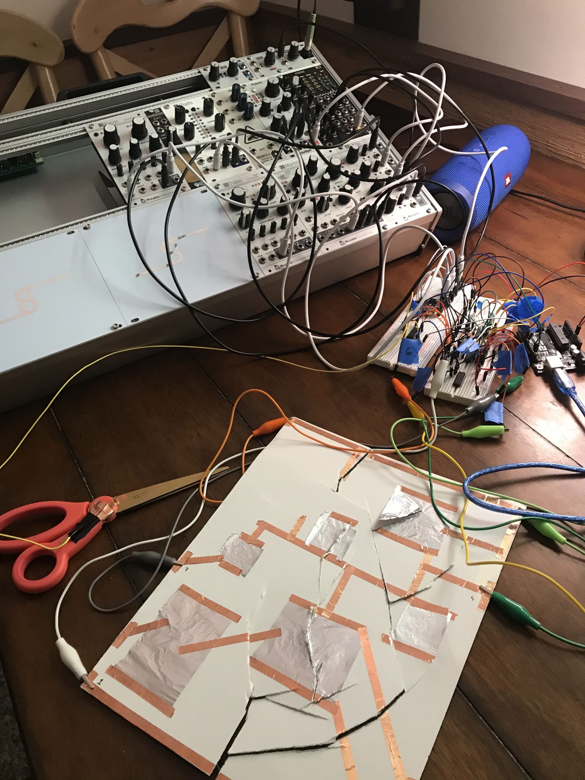
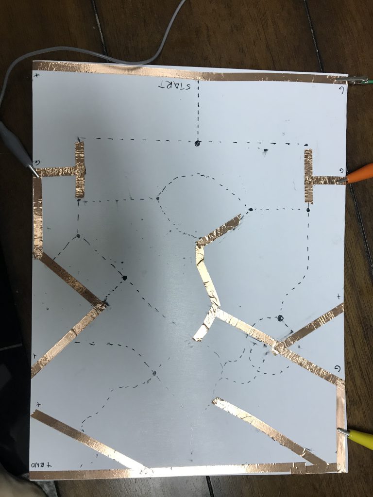
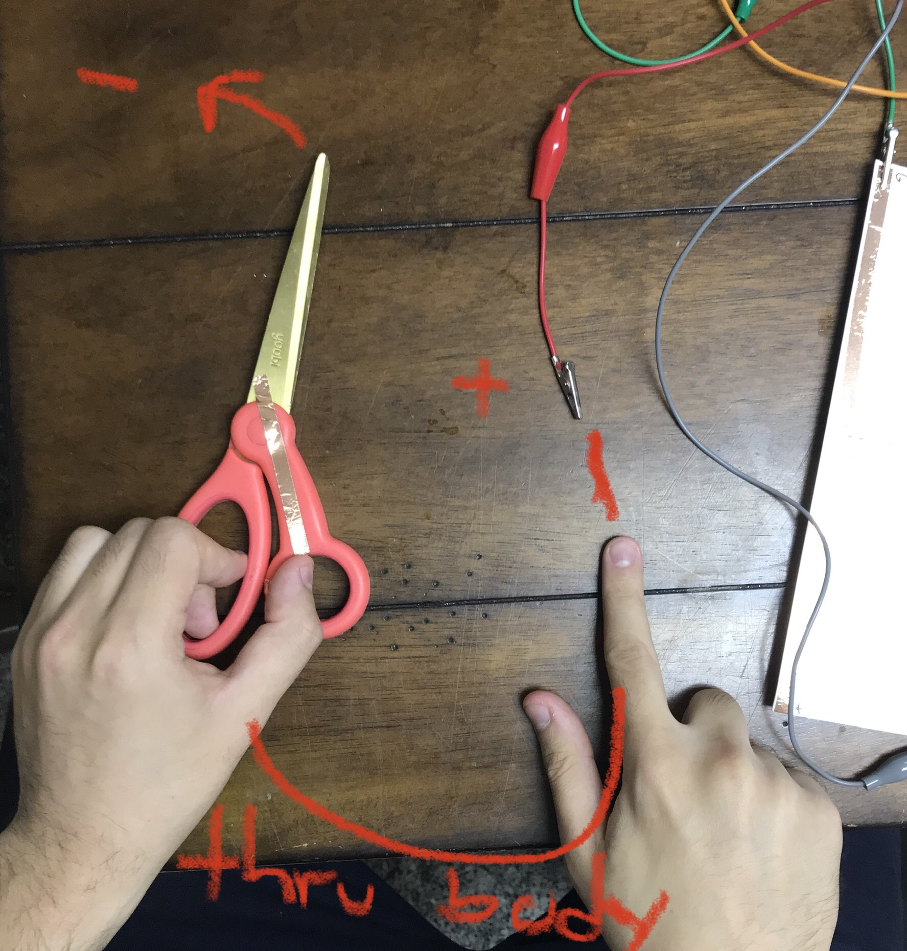 Originally, the plan was for the signal to be transmitted through the body like so. However, this proved to not be feasible as the body introduced too much resistance.
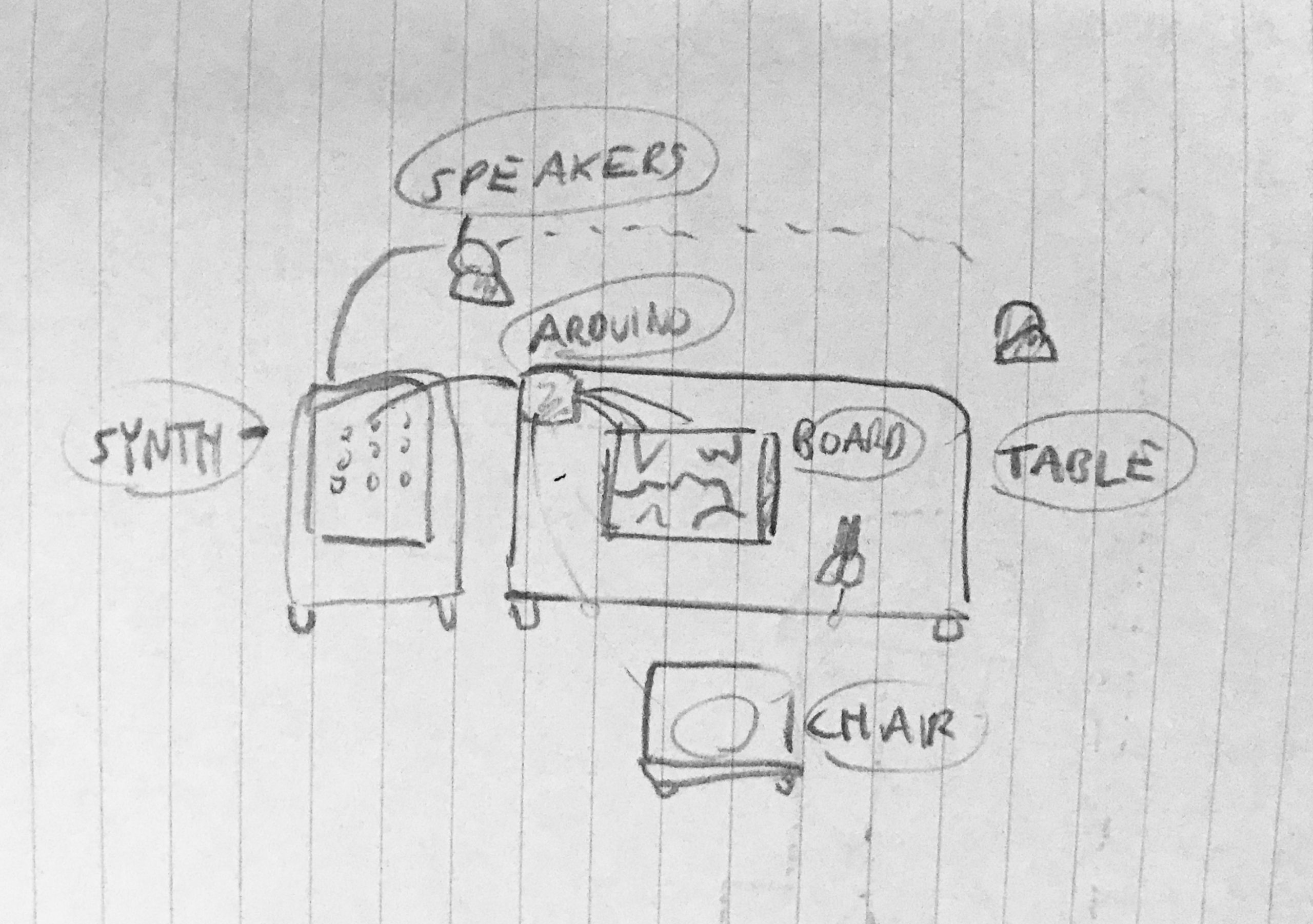

Comments are closed.