
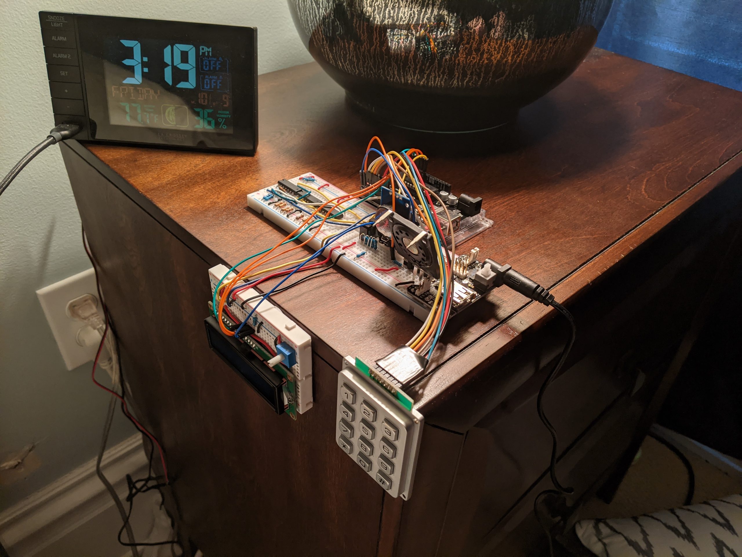
The main apparatus…
Description
This device was referred to as the “Workaholic’s Calendar” during development, but this has since been changed to “Workaholic’s Clock” since it really is just a clock that tells you whether or not you can go to work.
In order to be able to go to work, the following criteria must be met:
- You must not be sick.
- Hunt Library must be open.
- If Hunt Library is closed, you must input the correct 5-digit passcode to disarm security.
The device has 3 main inputs and is controlled by an Arduino and a hard-wired logic circuit. The first input is an infrared break-beam sensor, which is there to detect whether or not you have taken the tissue–doing so would indicate that you are sick. You will get fired if you decide to come in anyway. The second input is a real-time clock, which the Arduino polls in order to determine whether or not Hunt Library (my workplace) is open. If it is open, then pressing * on the keypad will tell the Arduino to probe the logic circuit. If Hunt is closed, then the Arduino will probe the logic circuit once a 5-digit code is entered . If the output of that circuit is high (true), then you can go to work because the necessary conditions were met. If the output is low (false), then you get fired, and a certain message will be displayed, along with an accompanying sound depending on the reason for which you were fired.
In the case where Hunt is open, there is no need to enter a code, and the only thing that would cause you to get fired is sickness.
In the case where Hunt is closed, there are a few more possibilities. You must enter a 5-digit code. If the code is incorrect and you are sick, then you reach the “critical failure” output, where you not only infect everyone but also get arrested by “The Crops.” If the code is incorrect, but you aren’t sick, then you are arrested by “The Crops.” If the code is correct, but you are sick, then you infect everyone. In any of these cases, you get fired.
If Hunt is closed, but you enter the correct code to disarm security and you aren’t sick, then you can come in to work (sneakily, you devil).
Here are some shots of the device working under certain circumstances…
When Hunt is open, but you’re sick…
When you enter the correct code to disarm security, but you’re sick…
When you aren’t sick, but you enter the wrong code to disarm security…
When you are sick AND you enter the wrong code to disarm security…
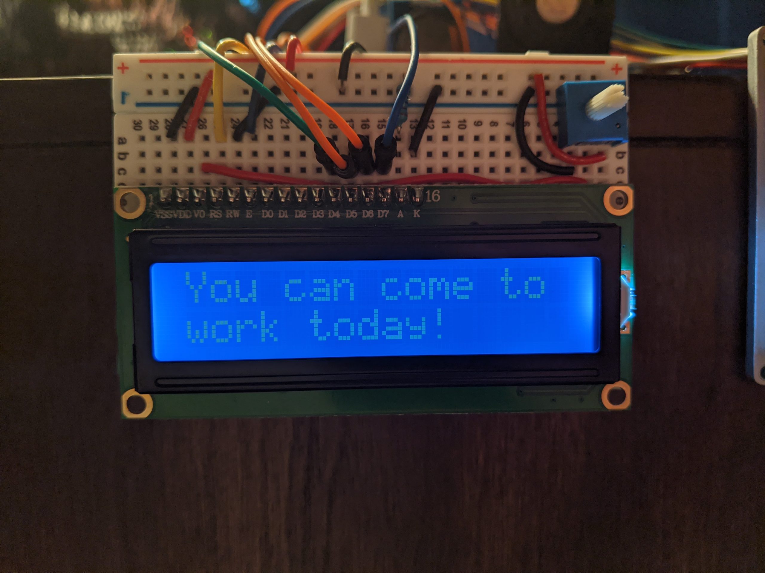
When you aren’t sick and you properly disarm security…
When Hunt is open and you aren’t sick…
Process Images
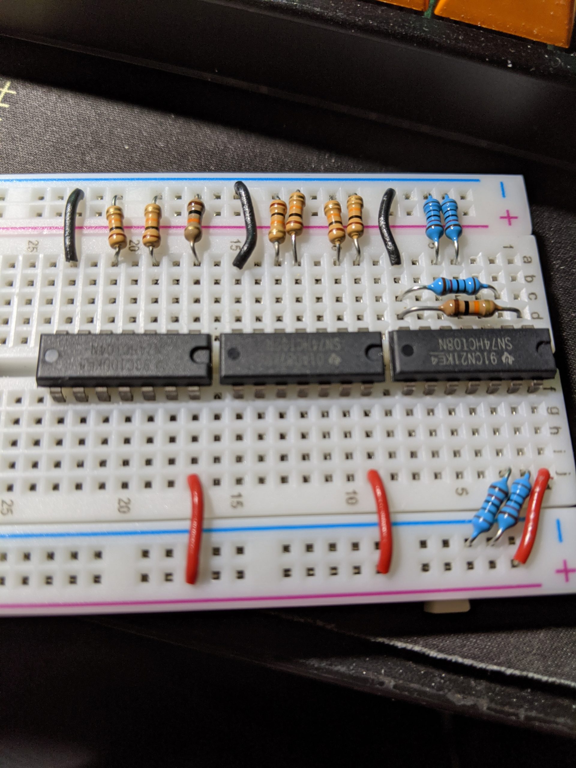
Here is the hard-wired logic circuit after completion. When I first wired it up, I accidentally pulled the outputs low, rather than the inputs. This picture is from after I remedied that. From right to left, 7408 quad-AND gate, 7432 quad-OR gate, 7404 hex inverter (six NOT gates). All inputs are pulled low using 10k ohm resistors.
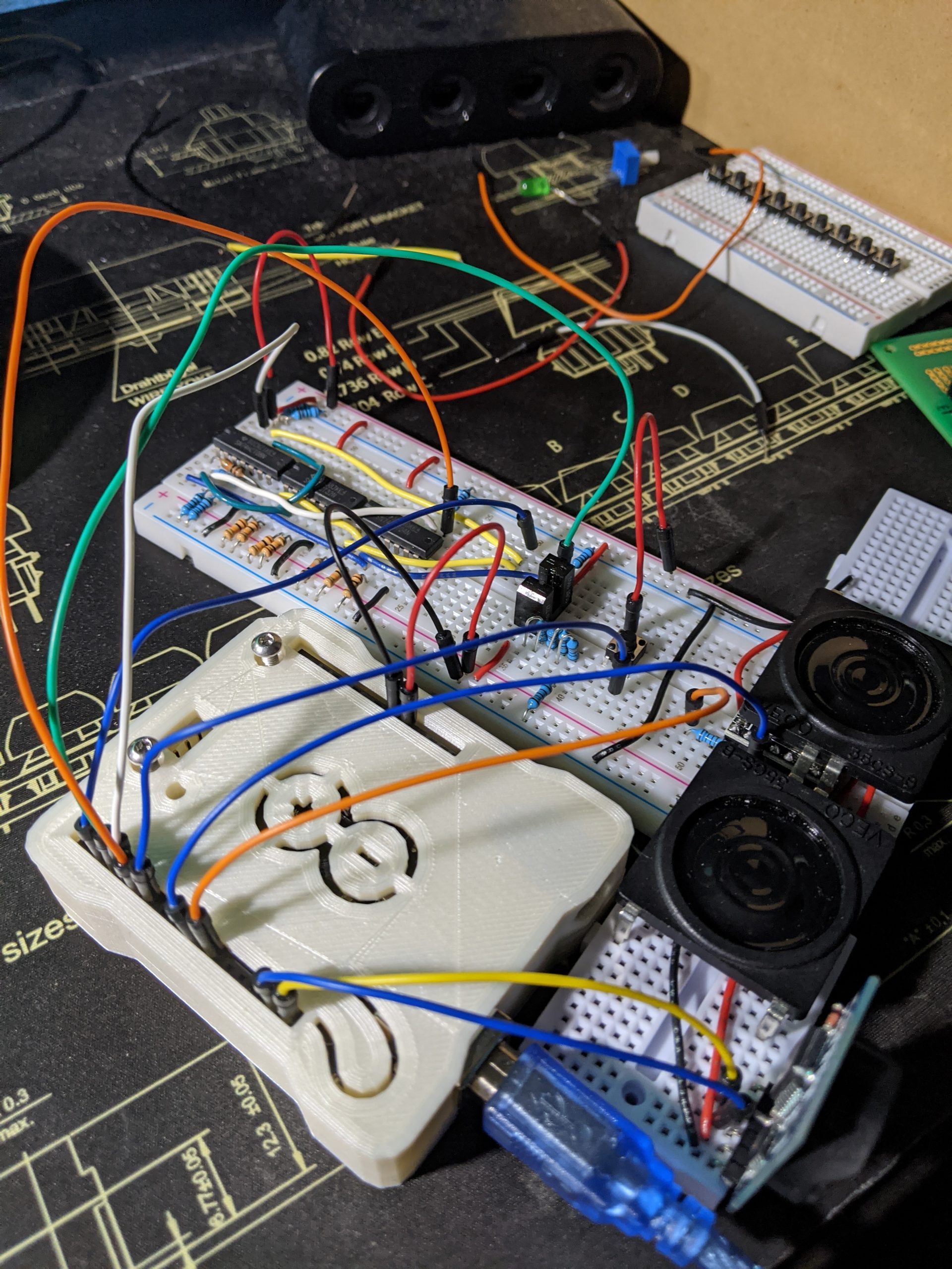
Here’s the device after initially wiring up the Arduino. The only components missing are the LCD and keypad. As you can see, the wiring is quite messy, but more alarmingly, the power is all coming from the Arduino. This is not enough to power everything properly and is ultimately what caused the problem shown in the video below… pardon my French…
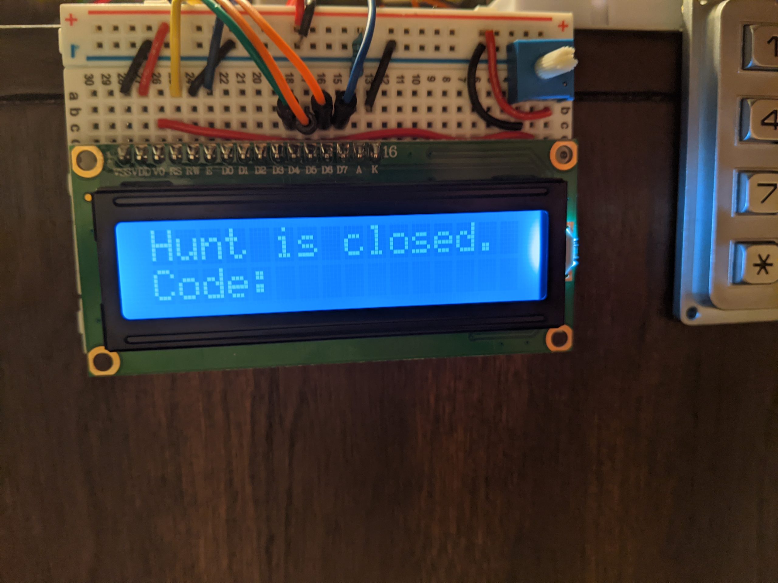
Here’s the device after I got the keypad and LCD working. This was the final major hurdle in the build process. I actually had to start using pins 0 and 1 on the Arduino for communicating with the DFPlayer Mini so that I would have enough pins that weren’t A4 and A5 (which you can’t use when using I2C devices like the RTC). To get around problems when uploading code to the Arduino, I just unplug pins 0 and 1 and then plug them back in once the Arduino is ready.
And this was the most satisfying part–getting to come in to work with all parts working correctly.
Process Reflection
The hardest part, after all was said and done, was getting everything to look somewhat neat, while still remaining in the realm of breadboards and jumpers. I had originally planned to enclose parts within their own custom-fabricated enclosures to tidy the device up, but due to my own poor time management and the challenging circumstances brought about by the COVID-19 pandemic, obtaining such parts would prove impossible. As a result, breadboards and jumpers ended up being the final aesthetic. Another issue (closely related to the previous one) was that I never managed to separate the break-beam sensor from the breadboard, as I didn’t have a suitable enclosure that would allow me to thread a tissue through it. I still plan on addressing this at some point when things are a little less frantic, but for now, it is what it is.
I ended up learning (or in some cases, re-learning) quite a lot about the limitations of the Arduino Uno platform, mostly relating to the pinout of its microcontroller. For instance, I re-learned that you can’t use pins A4/A5 and SDA/SCL at the same time, as they conflict. I also learned that you CAN use pins 0 and 1, so long as you unplug whatever device is connected to them whenever you need to upload code to the Arduino, and you don’t use the built-in serial monitor/plotter. Lastly, I learned that quite a few components are picky about how much power they receive and just won’t work right if you don’t give them enough. This ultimately stopped me from using the Elegoo Power Supply Module, as it wouldn’t supply enough power to the DFPlayer Mini given the audio setup I wanted to use. This was the case even when it was plugged into a 12V, 2A DC power supply, which should’ve been more than enough.
Despite the issues encountered, I’m actually pretty happy not just with the outcome, but also with what I learned about working with dedicated logic ICs and re-learned about working with the Arduino.
Code
Main program:
/*
   Workaholic's Clock (62-362 Project 1)
   Seth Geiser (sgeiser)

   Collaboration: Reference code and the guides I used for setting and accessing the RTC, setting, storing, and reading the passcode and keypad input, as well as outputting to the LCD can be found at these links:
   RTC: https://create.arduino.cc/projecthub/MisterBotBreak/how-to-use-a-real-time-clock-module-ds3231-bc90fe
   Keypad and passcode: https://www.instructables.com/Arduino-password-lock/
   LCD: Used guide from the Elegoo Super Starter Kit UNO R3 Project.

   Pin mapping:

   pin      | mode       | description
   ---------|------------|------------
   SDA/SCL   I2C          Real-time Clock
   0         RX           DFPlayer Mini TX
   1         TX           DFPlayer Mini RX
   2-8       I/O          Keypad
   9         INPUT_PULLUP Read output of main hard-wired logic...
   10        OUTPUT       Send hi/lo to main logic based on RTC
   11        INPUT        Read state of sick sensor for determining cause of firing (in part to determine which sound to play)
   12        LCD          LCD RS
   13        LCD          LCD Enable
   A0        LCD          LCD D4
   A1        LCD          LCD D5
   A2        LCD          LCD D6
   A3        LCD          LCD D7

*/
#include <ds3231.h>
#include <Wire.h>
#include <Keypad.h>
#include <LiquidCrystal.h>
#include <EEPROM.h>
#include <SoftwareSerial.h>
#include <DFRobotDFPlayerMini.h>

const int passLen = 5;

const int readOutput1 = 9;
const int huntPin = 10;
const int sickPin = 11;

LiquidCrystal lcd(12, 13, A3, A2, A1, A0);

char password[passLen];
char pass[passLen], pass1[passLen];
int i = 0;
char customKey = 0;

bool arrested = false;
bool infected = false;

const byte ROWS = 4; // four rows
const byte COLS = 3; // four columns
char hexaKeys[ROWS][COLS] = {
  {'1', '2', '3'},
  {'4', '5', '6'},
  {'7', '8', '9'},
  {'*', '0', '#'}
};

byte rowPins[ROWS] = {5, 3, 2, 7};
byte colPins[COLS] = {4, 8, 6};

// initialize a new instance of class Keypad
Keypad customKeypad = Keypad( makeKeymap(hexaKeys), rowPins, colPins, ROWS, COLS);

struct ts t; // Be sure to set the RTC using setRTC.ino

// RX, TX, disconnect when uploading sketch!!!
SoftwareSerial mySoftwareSerial(0, 1);
DFRobotDFPlayerMini myDFPlayer;

void setup() {
  mySoftwareSerial.begin(9600);
  Wire.begin();
  lcd.begin(16, 2);
  DS3231_init(DS3231_INTCN); // Initialize connection to RTC...
  pinMode(huntPin, OUTPUT);
  pinMode(sickPin, INPUT);
  pinMode(readOutput1, INPUT_PULLUP);

  if (!myDFPlayer.begin(mySoftwareSerial)) {
    // Use softwareSerial to communicate with DFPlayer Mini.
    while (true);
  }

  // Set serial communictaion time out 500ms
  myDFPlayer.setTimeOut(500);
  // Set volume value (range 0-30).
  myDFPlayer.volume(15);
  myDFPlayer.EQ(DFPLAYER_EQ_NORMAL);
  myDFPlayer.outputDevice(DFPLAYER_DEVICE_SD);

  lcd.print("CMU IDeATe");
  lcd.setCursor(0, 1);
  delay(1000);
  lcd.print("BOOTING DEVICE");
  delay(2000);
  lcd.clear();
  DS3231_get(&t); // Probe RTC
  if (t.hour >= 19 || t.hour <= 8) {
    digitalWrite(huntPin, HIGH); // Hunt is closed, Q3=T
    lcd.setCursor(0, 0);
    lcd.print("Hunt is closed.");
    lcd.setCursor(0, 1);
    lcd.print("Code: ");
    for (int j = 0; j < passLen; j++) {
      pass[j] = EEPROM.read(j); // Read password from built-in EEPROM
    }
  }
  else {
    digitalWrite(huntPin, LOW); // Hunt is open, Q3=F
    lcd.setCursor(0, 0);
    lcd.print("Welcome to Hunt.");
    lcd.setCursor(0, 1);
    lcd.print("Press '*'");
  }
}

void loop() {
  customKey = customKeypad.getKey(); // Read keypad...
  if (digitalRead(sickPin)) {
    infected = true;
  }
  else if (!digitalRead(sickPin)) {
    infected = false;
  }
  if (t.hour >= 19 || t.hour <= 8) { // Hunt closed...
    if (customKey) {
      password[i++] = customKey;
      lcd.print(customKey);
    }
    if (i == passLen) {
      i = 0;
      delay(200);
      for (int j = 0; j < passLen; j++)
        pass[j] = EEPROM.read(j);
      if (!strncmp(password, pass, passLen)) {
        i = 0;
        lcd.setCursor(0, 0);
        lcd.print("Passkey Accepted,");
        lcd.setCursor(0, 1);
        lcd.print("Welcome 2 IDeATe");
        delay(3000);
        digitalWrite(huntPin, LOW); // Open Hunt Library, disarm security...
        submit();
      }
      else {
        i = 0;
        lcd.clear();
        lcd.print("Access Denied...");
        delay(3000);
        arrested = true;
        submit();
      }
    }
  }
  else if (customKey == '*') {
    submit();
  }
}

void submit() {
  lcd.clear();
  if (digitalRead(readOutput1)) {
    // Logic is outputting LOW into a NOT-gate. Since the pin is being pulled up, pin 9 is connected to the output of the NOT-gate...
    lcd.setCursor(0, 0);
    lcd.print("You're fired!");
    lcd.setCursor(0, 1);
    if (arrested && infected) {
      lcd.print("Busted AND sick.");
      myDFPlayer.play(2); // 0002_get_out.mp3
    }
    else if (infected) {
      lcd.print("You're sick.");
      myDFPlayer.play(4); // 0004_bruh.mp3
    }
    else if (arrested) {
      lcd.print("Busted!");
      myDFPlayer.play(1); // 0001_crops.mp3
    }
  }
  else { // Logic is outputting HIGH into a NOT-gate...
    lcd.setCursor(0, 0);
    lcd.print("You can come to");
    lcd.setCursor(0, 1);
    lcd.print("work today!");
    myDFPlayer.play(3); // 0003_scatman_world.mp3
  }
}
Set real-time clock:
#include <Wire.h>
#include <ds3231.h>

struct ts t;

void setup() {
  Serial.begin(9600);
  Wire.begin();
  DS3231_init(DS3231_INTCN);
  /*----------------------------------------------------------------------------
  In order to synchronise your clock module, insert timetable values below !
 ----------------------------------------------------------------------------*/
  t.hour=12;
  t.min=7;
  t.sec=0;
  t.mday=9;
  t.mon=10;
  t.year=2020;

  DS3231_set(t);
}

void loop() {
  DS3231_get(&t);
  Serial.print("Date : ");
  Serial.print(t.mday);
  Serial.print("/");
  Serial.print(t.mon);
  Serial.print("/");
  Serial.print(t.year);
  Serial.print("\t Hour : ");
  Serial.print(t.hour);
  Serial.print(":");
  Serial.print(t.min);
  Serial.print(".");
  Serial.println(t.sec);

  delay(1000);
}
Initialize EEPROM with default password of “12345”:
#include<EEPROM.h>

void setup() {
  // Passcode will be 5 digits long
  for (int j=0;j<5;j++) {
    EEPROM.write(j, j+49);
  }
}

void loop() {

}
Test password storage + retrieval and optionally change password stored in EEPROM:
/*
    +------------------------------------------------------------------------+
    |                                                                        |
    |               ARDUINO LOCK SYSTEM FIRMWARE v1.1.0                      |
    |                       BY: DIY MECHANICS                                |
    |    --------------------------------------------------------------      |
    |  written_by: suhail  project:HOME AUTOMATION:-passcode lock sytem v1.1 |
    |  facebook.com/suhail jr.                      twitter.com/suhail jr.   |
    |             visit more @ www.diymechanics.wordpress.com                |
    +------------------------------------------------------------------------+
*/

///////////////////////////////////////////////////////////////////////////////

#include <Keypad.h>
#include <LiquidCrystal.h>
#include <EEPROM.h>

//////////////////////////////////////////////////////////////////////////////

LiquidCrystal lcd(12, 13, A3, A2, A1, A0);
const int passLen = 5;
char password[passLen];
char pass[passLen], pass1[passLen];
int i = 0;
char customKey = 0;

//////////////////////////////////////////////////////////////////////////////

const byte ROWS = 4; // four rows
const byte COLS = 3; // four columns
char hexaKeys[ROWS][COLS] = {
  {'1', '2', '3'},
  {'4', '5', '6'},
  {'7', '8', '9'},
  {'*', '0', '#'}
};

///////////////////////////////////////////////////////////////////////////////

byte rowPins[ROWS] = {5,3,2,7}; // connect to the row pinouts of the keypad
byte colPins[COLS] = {4,8,6}; // connect to the column pinouts of the keypad
//initialize an instance of class NewKeypad
Keypad customKeypad = Keypad( makeKeymap(hexaKeys), rowPins, colPins, ROWS, COLS);

////////////////////////////////////////////////////////////////////////////////////

void(* resetFunc) (void) = 0;
void setup() {
  lcd.begin(16, 2);
  lcd.print("STARK-TECHNOLOGY");
  lcd.setCursor(0, 1);
  delay(4000);
  lcd.print("BOOTING DEVICE");
  delay(1000);
  lcd.clear();
  lcd.print("KEYPAD-LOCKED");
  lcd.clear();
  lcd.print(" Passcode Please:");
  lcd.setCursor(0, 1);
  for (int j = 0; j < passLen; j++) {
    pass[j] = EEPROM.read(j);
  }

  ////////////////////////////////////////////////////////////////////////////////////

}
void loop()
{
  customKey = customKeypad.getKey();
  if (customKey == '#') {
    change();
  }
  if (customKey == '*') {
    resetFunc();
  }
  if (customKey) {
    password[i++] = customKey;
    lcd.print(customKey);
  }

  if (i == passLen) {
    i = 0;
    delay(200);
    for (int j = 0; j < passLen; j++) {
      pass[j] = EEPROM.read(j);
    }
    if (!(strncmp(password, pass, passLen))) {
      i = 0;
      lcd.clear();
      lcd.print("Passkey Accepted");
      lcd.setCursor(0, 1);
      lcd.print("#-Change");
      lcd.print("*-Lock");
    }
    else {
      lcd.clear();
      lcd.print("Access Denied...");
      lcd.clear();
      lcd.print("restarting...");
      delay(5000);
      i = 0;
      resetFunc();
    }
  }
}

////////////////////////////////////////////////////////////////////////////////////

void change() {
  int j = 0;
  lcd.clear();
  lcd.print("Current Passcode:");
  lcd.setCursor(0, 1);
  while (j < passLen) {
    char key = customKeypad.getKey();
    if (key) {
      pass1[j++] = key;
      lcd.print(key);
    }
    key = 0;
  }
  delay(500);

  if ((strncmp(pass1, pass, passLen))) {
    lcd.clear();
    lcd.print("Wrong Passkey...");
    lcd.setCursor(1, 1);
    lcd.print("DENIED");
    delay(2000);
    customKey = 0;
    resetFunc();
  }
  else {
    j = 0;
    lcd.clear();
    lcd.print("New Passcode:");
    lcd.setCursor(0, 1);
    while (j < passLen) {
      char key = customKeypad.getKey();
      if (key) {
        pass[j] = key;
        lcd.print(key);
        EEPROM.write(j, key);
        j++;
      }
    }
    lcd.print("  Done......");
    delay(1000);
    resetFunc();
  }
}
Comments are closed.