- Narrative description.
- Force Simulator.
- Our project inspires wonder by creating an unexpected and seemingly impossible result through gesture. Children will be able to make things fly remotely.
- Location: Slanted wall room or hallway.
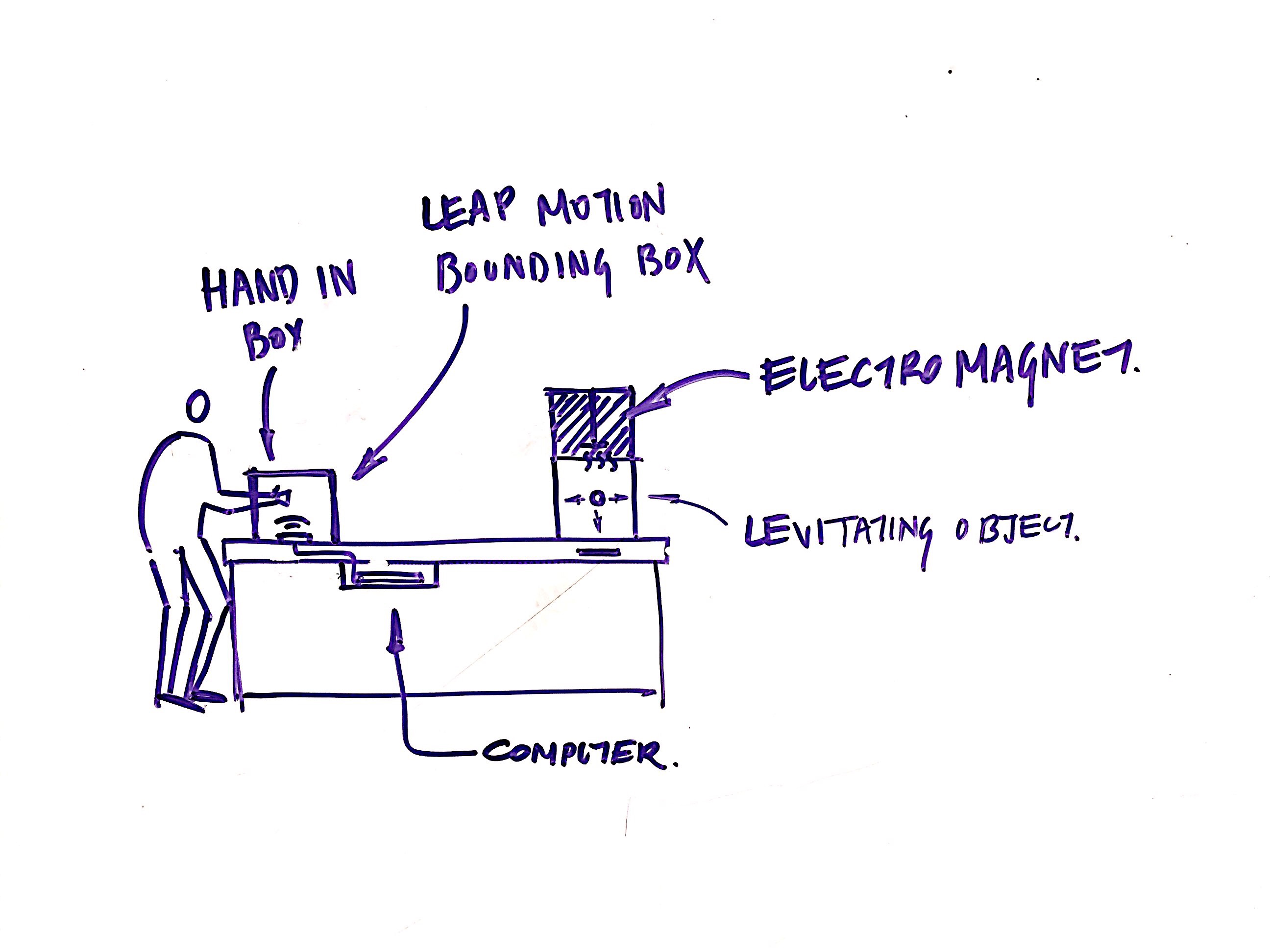
- When approaching the experience, the visitor would see either a box or an empty fixed glove that they can put their hand into. When they place their hand in the box/ glove, the object on the opposite side of the table would immediately react and begin to levitate. With simple gestures and positional changes,
- Kids being able to realize that they are making things fly. We think this would be very exciting for them, and cause much desire to return to the machine.
- Technical outline.
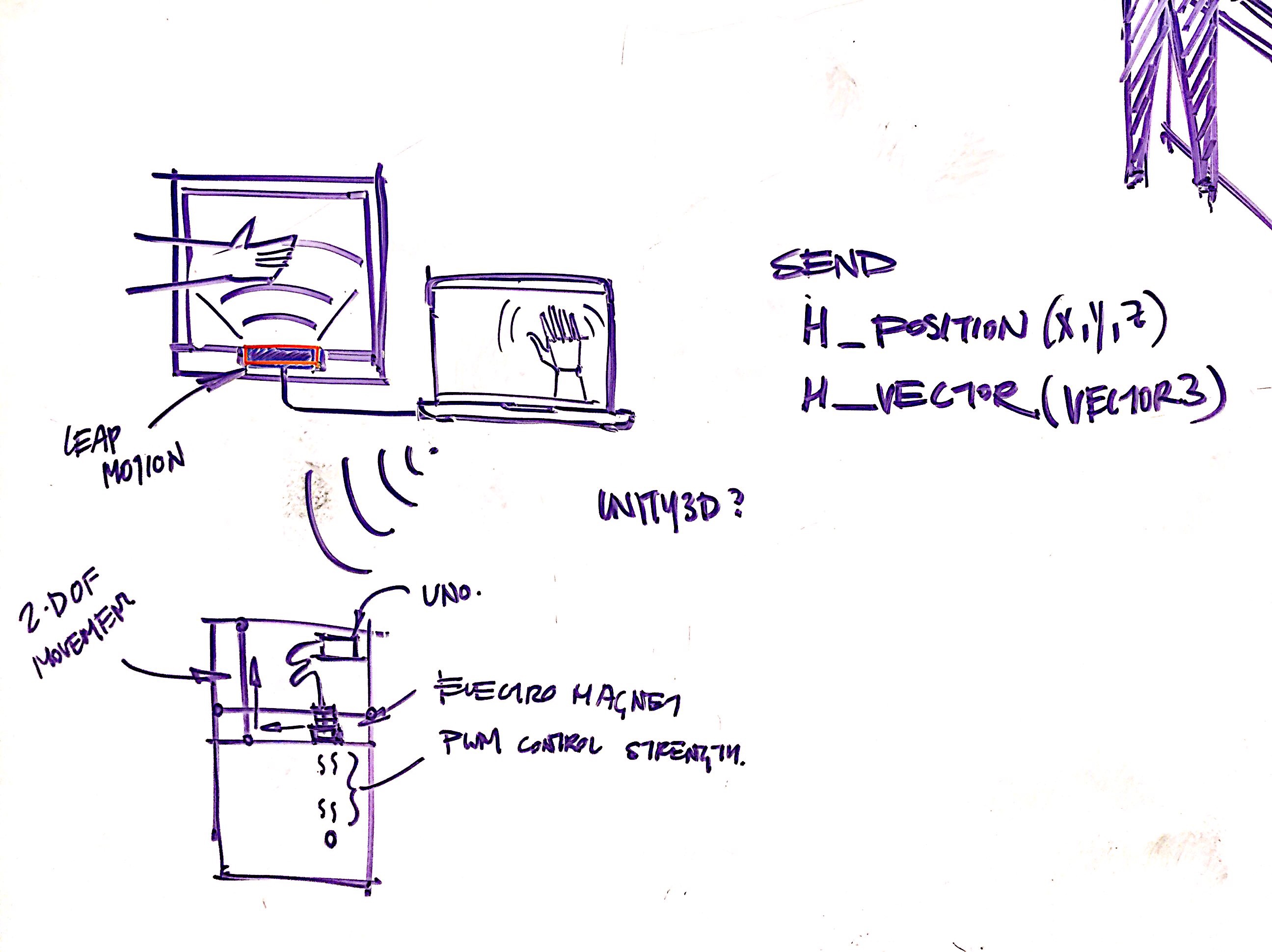
- Short summary of the first-draft technical solution. Using a leapmotion, we will send hand y coordinates to tell the output, either a fan or an electromagnet, to raise or lower an object in a closed environment. There could also be a small display, from the leapmotion output, showing a “sci-fi” hand mimicking the user’s motions.
- What kind of materials, structure, and mechanism? We need acrylic to make the bounding box, wood for the main module container, and cloth sheets for secrecy.
- What kind of sensors, actuators, and algorithms? The primary sensor would be the leap motion controller. To cause the object to levitate, we would either use an electromagnet or a fan. This levitation mechanism would be moving on a xyz axis based on the hand positioning.
- What are the key technical challenges? Getting the fan or electromagnet to reach the desired effect of continuous levitation.
- Project management.
- Designated individual responsibilities, as applicable. Warren- Electromagnetic effect and voltage calculations. Soonho — Leap Motion and Housing
- Objectives for the proof-of-concept demonstration. Floating magnets with variable height based off of current. Leap Motion input translated into some sort of meaningful data.
- Objectives for the first on-site test. Functional interaction between leap motion and electromagnets
- Known unknowns and contingencies. What cannot be decided now but may be revealed by a proof-of-concept test? What will be the possible alternatives from which to choose? Materials for building the housing units for our components. Method for moving around the magnetic rig.
- Budget outline.
- Identification of any special materials to be purchased or obtained.
- Bill of materials, including approximate quantities.
- Approximate cost estimates and total spending.
- If you exceed the amount promised from the course budget, please explain how the group will negotiate out-of-pocket spending.
| Part | CostxUnit | Quantity |
| Uxcell Electromagnet | 12.50 | 2 |
| Leapmotion | 70 | 1 |
| Total | 95 |
- Timeline. Please specify dates for the following milestones:
- Proof-of-concept test to clarify known unknowns. 10/30
- Design of custom parts. 11/3
- Purchasing of special materials or parts.11/3
- Fabrication of custom parts.11/10
- Mechanical and electrical assembly. 11/17
- Programming. 11/24
- Lab testing and debugging. 11/24
- On-site testing (see Fall 2017 Calendar).
- Sketches.
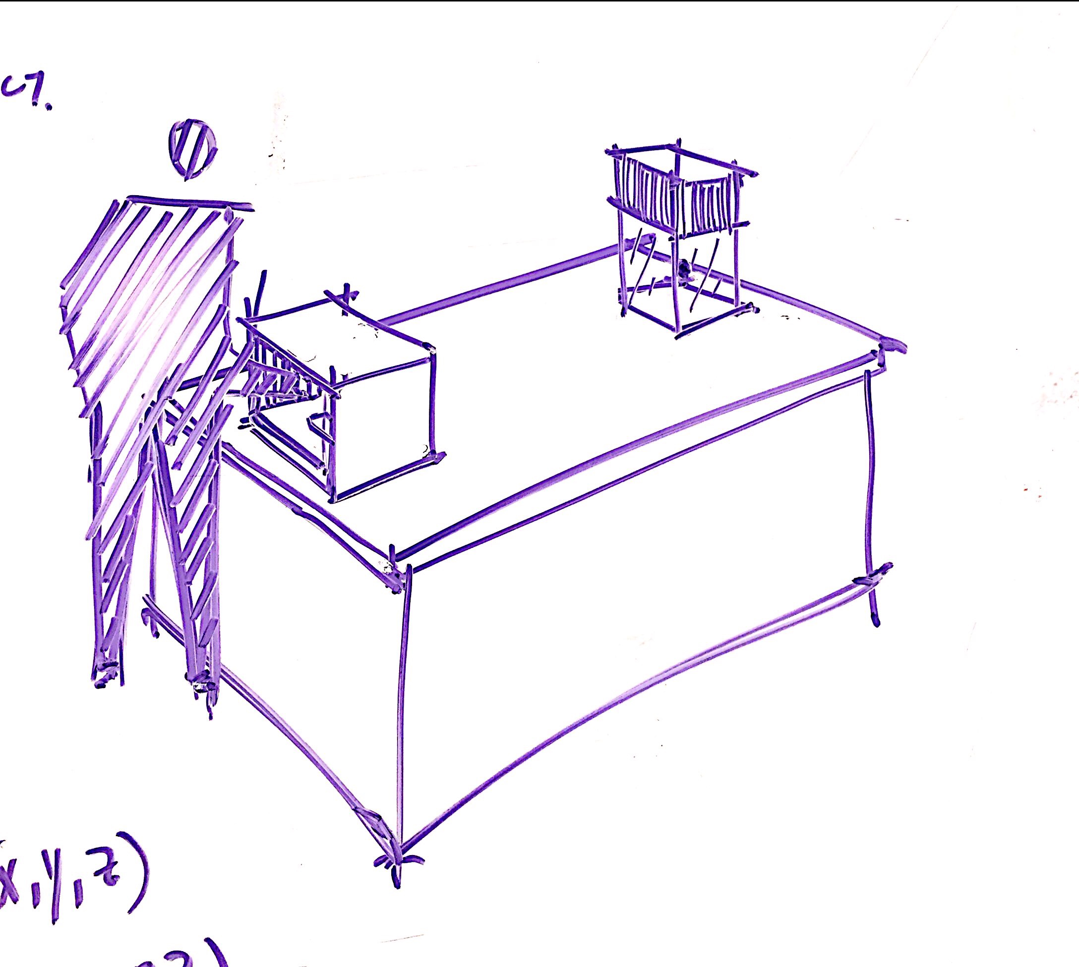
- Isometric or perspective view of the overall device or installation. Please include scale and units. Roughly a two foot module held on a table. There will be a bounding box in front of the electromagnet array that will be designated for gesture interaction, roughly a 1 foot cube.
Leave a Reply
You must be logged in to post a comment.