Webots Modeling

New for 2026. Draft notes - work in progress.

Exploring a machine idea using the Webots open source robot simulator could involve creating a new robot model. Please see Robot Simulation Design for an introduction to the general principles involved in simulation design. These notes are a brief, practical guide to implementing a rigid-body simulation model within the Webots system.

The Scene Tree

The Webots Scene Tree is a graph-based representation of an entire simulation. An individual robot is represented by a Robot node which typically appears at the root level of the scene. The Robot sub-tree may be entirely contained in the world file and interactively edited in the GUI, but may also be generated by a proto script and edited via a text editor. Either way, the following notes will help you parse and edit the robot tree structure.

ZYY Arm Kinematics and Geometry

The following example is extracted from the ZYY Robot Arm Model to highlight the tree nodes essential for the kinematic representation of the arm. Each Robot and Solid node is a container corresponding to a single rigid body. Each Shape node specifies geometry available for rendering, contact detection, or mass properties. Each HingeJoint node connects two rigid bodies with a joint.
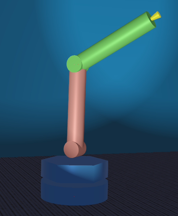
../_images/zyy-arm.png

digraph zyy_kinematics { node [fontsize=10] edge [fontsize=8] dpi="72" size="7,7!" // declare all nodes Robot [ label = "Robot (fixed base)"] Shape0 [ label = "Shape (base cylinder)"] Joint1 [ label = "HingeJoint 1 (shoulder Z)"] Joint2 [ label = "HingeJoint 2 (shoulder Y)"] Joint3 [ label = "HingeJoint 3 (elbow Y)"] Solid1 [ label = "Solid (rotating platform)"] Solid2 [ label = "Solid (proximal arm link)"] Solid3 [ label = "Solid (distal arm link)"] Shape1 [ label = "Shape (shoulder cylinder)"] Shape2 [ label = "Shape (proximal link cylinder)"] Shape3 [ label = "Shape (distal link cylinder)"] // declare all edges Robot -> Joint1 [label = "children"] Joint1 -> Solid1 [label = "endPoint"] Solid1 -> Joint2 [label = "children"] Joint2 -> Solid2 [label = "endPoint"] Solid2 -> Joint3 [label = "children"] Joint3 -> Solid3 [label = "endPoint"] Robot -> Shape0 [label = "children"] Solid1 -> Shape1 [label = "children"] Solid2 -> Shape2 [label = "children"] Solid3 -> Shape3 [label = "children"] label = "Essential kinematics and geometry of the ZYY Arm model. Other nodes have been omitted for clarity." }

ZYY Arm Dynamics and Contact

Following is an SVG figure showing more of the ZYY tree, now including the dynamics and contact nodes essential for physical simulation. It may be easier to read by opening the frame in a separate window, if your browser allows. This still omits other slots and nodes for other Webots properties, e.g. sensors.

  • Each Shape is a container for geometry (e.g. Cylinder) and rendering properties (Appearance)

  • Each Shape is contained within a Pose which positions the geometric coordinate frame for the primitive within the rigid body coordinate frame.

  • Each Solid includes Physics to enable dynamics and specify mass properties for a single rigid body.

  • Each Solid includes a boundingObject slot to specify collision geometry. In this model, the same geometry is used for calculating mass properties.

  • Each HingeJoint includes an actuator in the device slot. Note that the actuator has no intrinsic mass or geometry.

  • The boundingObject slots use a DEF/USE mechanism to link to the Shape objects. Each Shape includes a named DEF, each boundingObject uses a named USE to invoke it.

digraph zyy_physics { node [fontsize=10] edge [fontsize=8] dpi="72" size="24,24!" // declare all nodes Robot [ label = "Robot (fixed base)"] Shape0 [ label = "Shape (base cylinder)"] Joint1 [ label = "HingeJoint 1 (Z shoulder)"] Joint2 [ label = "HingeJoint 2 (Y shoulder)"] Joint3 [ label = "HingeJoint 3 (Y elbow)"] Solid1 [ label = "Solid (rotating platform)"] Solid2 [ label = "Solid (proximal arm link)"] Solid3 [ label = "Solid (distal arm link)"] Shape1 [ label = "Shape (shoulder cylinder)"] Shape2 [ label = "Shape (proximal link cylinder)"] Shape3 [ label = "Shape (distal link cylinder)"] Pose0 [ label = "Pose (base geom location)"] Pose1 [ label = "Pose (platform geom location)"] Pose2 [ label = "Pose (proximal link geom location)"] Pose3 [ label = "Pose (distal link geom location)"] Physics0 [ label = "NULL (base is immobile)"] Physics1 [ label = "Physics (platform mass properties)"] Physics2 [ label = "Physics (proximal link mass properties)"] Physics3 [ label = "Physics (distal link mass properties)"] JointParameters1 [ label = "JointParameters (joint 1 axis and limits)" ] JointParameters2 [ label = "JointParameters (joint 2 axis and limits)" ] JointParameters3 [ label = "JointParameters (joint 3 axis and limits)" ] Motor1 [ label = "RotationalMotor (motor1 gains and limits)"] Motor2 [ label = "RotationalMotor (motor2 gains and limits)"] Motor3 [ label = "RotationalMotor (motor3 gains and limits)"] Appearance0 [ label = "Appearance (base color)"] Appearance1 [ label = "Appearance (platform color)"] Appearance2 [ label = "Appearance (proximal link color)"] Appearance3 [ label = "Appearance (distal link color)"] Cylinder0 [ label = "Cylinder (base geometry)"] Cylinder1 [ label = "Cylinder (platform geometry)"] Cylinder2 [ label = "Cylinder (proximal link geometry)"] Cylinder3 [ label = "Cylinder (distal link geometry)"] // ================================================================ // declare all edges // key kinematic chain Robot -> Joint1 [label = "children"] Joint1 -> Solid1 [label = "endPoint"] Solid1 -> Joint2 [label = "children"] Joint2 -> Solid2 [label = "endPoint"] Solid2 -> Joint3 [label = "children"] Joint3 -> Solid3 [label = "endPoint"] // each Pose positioning geometry inside a Solid Robot -> Pose0 [label = "children"] Solid1 -> Pose1 [label = "children"] Solid2 -> Pose2 [label = "children"] Solid3 -> Pose3 [label = "children"] // each Pose contains a Shape Pose0 -> Shape0 [label = "children"] Pose1 -> Shape1 [label = "children"] Pose2 -> Shape2 [label = "children"] Pose3 -> Shape3 [label = "children"] // each Shape contains an appearance Shape0 -> Appearance0 [label = "appearance"] Shape1 -> Appearance1 [label = "appearance"] Shape2 -> Appearance2 [label = "appearance"] Shape3 -> Appearance3 [label = "appearance"] // each Shape contains a geometric primitive Shape0 -> Cylinder0 [label = "geometry"] Shape1 -> Cylinder1 [label = "geometry"] Shape2 -> Cylinder2 [label = "geometry"] Shape3 -> Cylinder3 [label = "geometry"] // each Joint has an axis and location Joint1 -> JointParameters1 [label = "jointParameters"] Joint2 -> JointParameters2 [label = "jointParameters"] Joint3 -> JointParameters3 [label = "jointParameters"] // each Joint has an actuator device Joint1 -> Motor1 [label = "device"] Joint2 -> Motor2 [label = "device"] Joint3 -> Motor3 [label = "device"] // each Solid has physics properties Robot -> Physics0 [label = "physics"] Solid1 -> Physics1 [label = "physics"] Solid2 -> Physics2 [label = "physics"] Solid3 -> Physics3 [label = "physics"] // each Solid has contact geometry Robot -> Pose0 [label = "boundingObject"] Solid1 -> Pose1 [label = "boundingObject"] Solid2 -> Pose2 [label = "boundingObject"] Solid3 -> Pose3 [label = "boundingObject"] label = "ZYY Arm model tree including physics. Still other nodes have been omitted for clarity." }

Actuator Model

The Motor actuator model in Webots defaults to position control using a simulated PID controller calculated inside the physics loop. The default parameters include PID gains [10,0,0] (i.e. undamped position control), and maxVelocity of 10 (about 95 RPM), and no position or acceleration limits.

The motor devices are identified by name, e.g.:

from controller import Robot
robot = Robot()
motor = robot.getDevice('motor1')

A Motor device can be switched to velocity mode by setting the position target to infinity:

motor.setPosition(math.inf)

A Motor device can be switched to pure torque or force mode by calling setTorque, bypassing the PID control, e.g.:

motor.setTorque(0)

The Clock Robot Model controller demonstrates torque mode by implementing PD position control in Python. Note that this controller runs at the event loop step rate which might be considerably slower than the underlying physics step rate.

Related topics from the Motor scene tree node documentation:

Course Model Examples

A few of the simulation models created for the course include related commentary on the design:

Webots Documentation

The online Webots User Guide includes tutorials which walk through many of the software features. The specific tutorial most closely to this discussion is Tutorial 6: 4-Wheeled Robot which walks through the creation of a a four-wheeled cart.

The online Webots Reference Manual includes much more detail needed to create simulation models. A few sections of particular interest:

  • Nodes describes all primitive scene tree data elements

  • PROTO documents the model scripting file format