Project Team: Dyani Robarge & Jack Fogel
Human Machine Virtuosity, Spring 2017
ABSTRACT
The Augmented Carve seeks to develop a woodworking tool guidance system for aiding in the construction of 3D aggregated irregular geometries, in this case branches. The motion capture system tracks the location and orientation of both tool, a ryoba pull saw, as well as individual wood parts. A projection directs the user where to make half lap cut to join two beaches together, ultimately creating the structure designed on the computer through a series of members.
OBJECTIVES
Rather than working with dimensional lumber, the half lap joinery connects a dense collection of large, irregular tree branches. Working with a catalog of highly-unique parts adds an extra challenge in building this augmented construction system. Our objective is to use this augmented system to make accurate, complex carves which vary in size, location and orientation. Our hope is that the precision of these complex intersections can be translated smoothly from digital model to physical work space.
IMPLEMENTATION
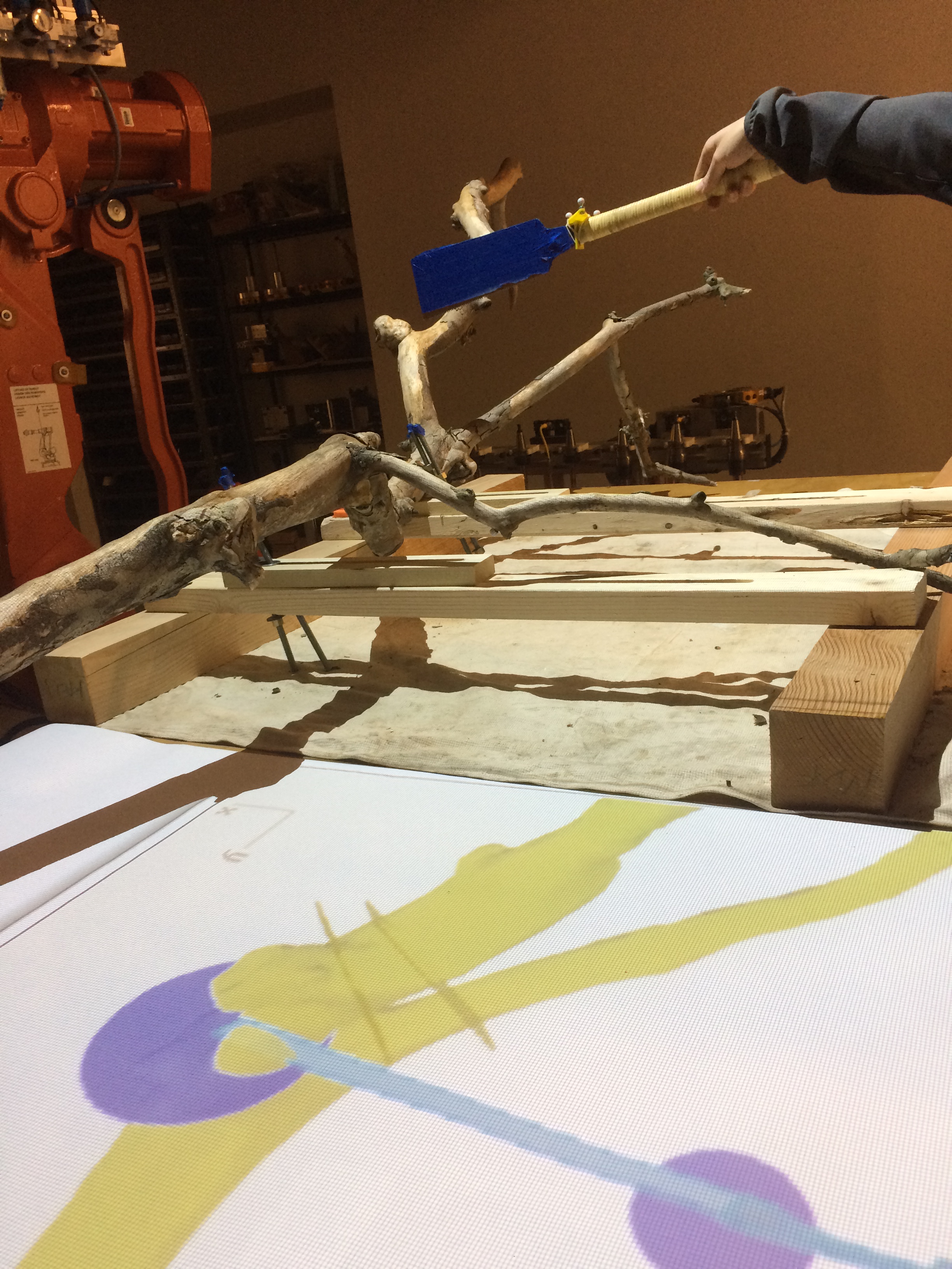
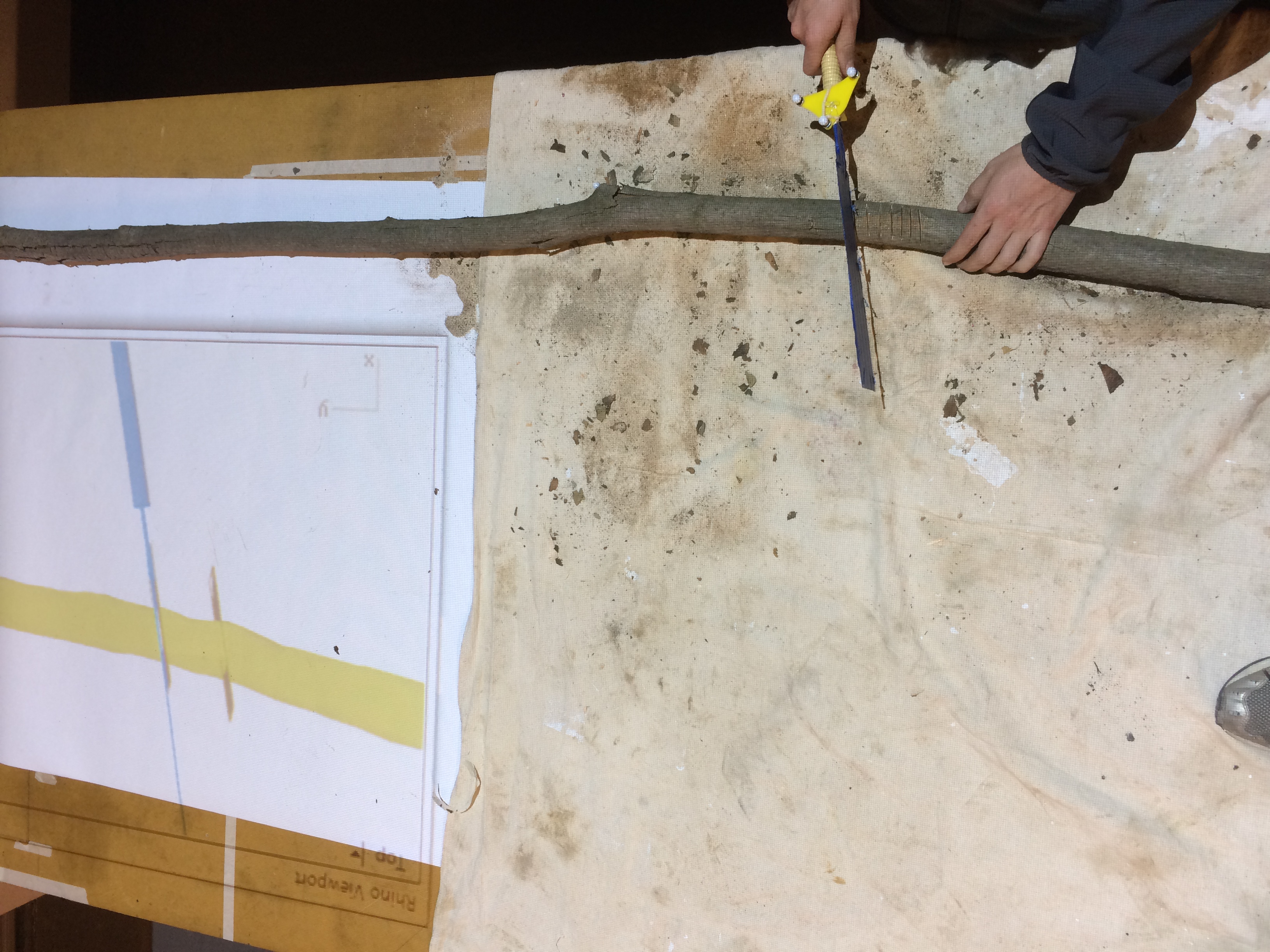
To start, individual branches are made into high-resolution digital models through the use of open source photogrammetry software. Once the mesh models are properly scaled and cataloged, 3-4 nodes are placed on each digital branch model. Holes are drilled into the physical branches concurrently to ensure an accurate representation of the motion capture nodes in digital space. Once the nodes are fixed in place, the branch and ryoba saw can be linked and tracked as ‘rigid bodies’ within the motion capture software. Using a projector, tracking data is displayed on the work table next to the user.
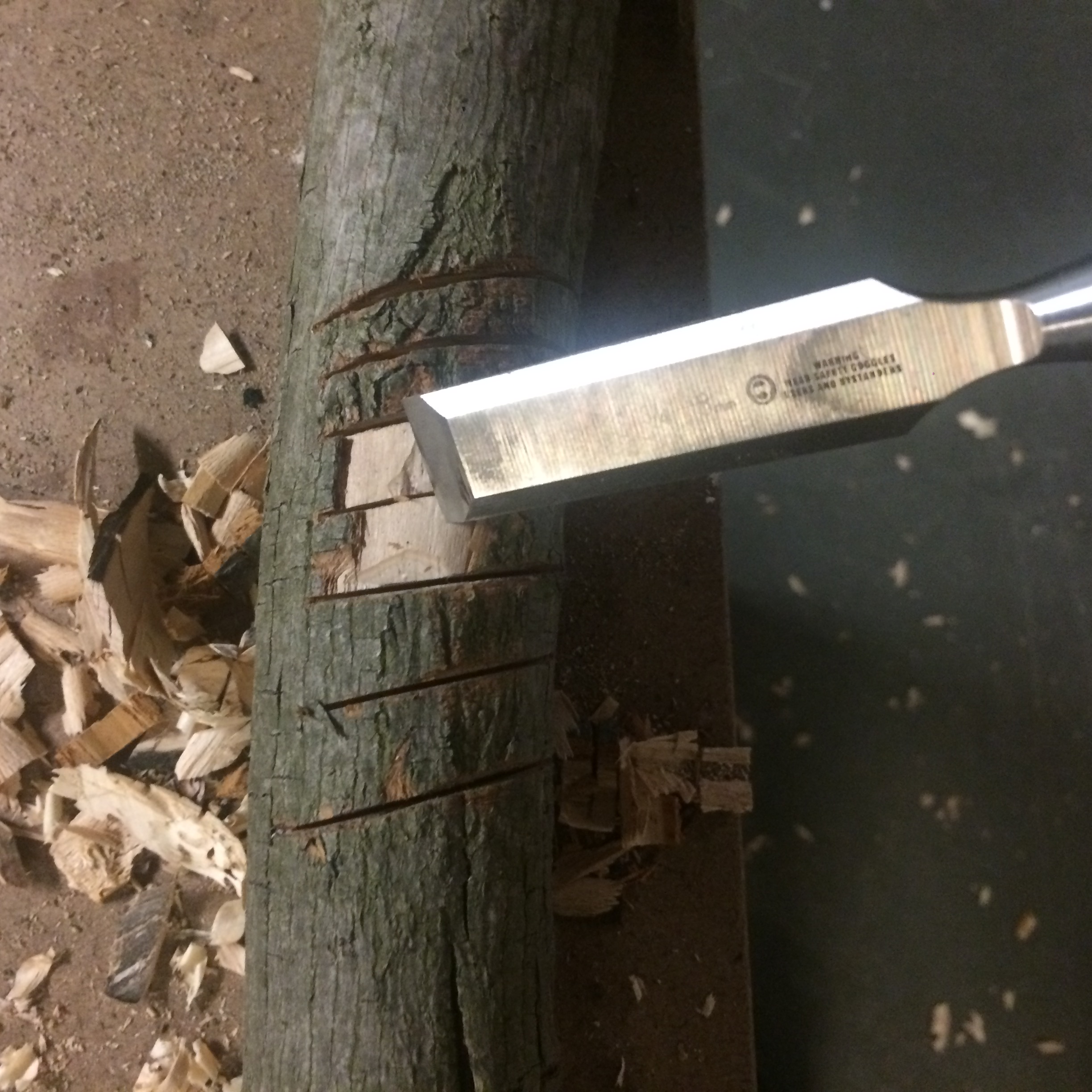
The worker then affixes the branch securely to the table, making sure to keep the carve areas visible and accessible. Our team initially designed a fixture to affix each branch to the work table, but after several carve tests with branches of various sizes we quickly found the fixture to be an unnecessary element in the process. Once the worker has their branch securely fastened, the saw can be aligned to each cut area.
As the user moves their tool and a branch into the work cell, a dynamic user interface occurs. The camera zooms in onto individual carve regions and out to view the entire work space depending on the proximity of the tool to each carve region. Carve regions are marked by two outer alignment curves. The lines help the worker guide their tool in space. Circles above the saw endpoints act as a virtual level by giving clear indication of correct approach angles for each unique carve. Relaying real-time feedback of the tool’s movements through space allows the motion capture system to guide the user as they work.
OUTCOMES
We feel that this woodworking guidance tool provides intuitive feedback to the user and yields relatively accurate results, however there is room for much improvement. The low resolution of the projector greatly affected the tolerance of cut location, however we aimed to make most of the cuts smaller so with a small adjustment they would fix snug. The interface is very clear to us to use as we designed it, however its unclear if others would have the same ease of use as we did not test it with others. Overall, there are several features we noted throughout the process of creating this system which could be improved and expanded upon, but as the project stands it accomplishes much of what we had hoped.
CONTRIBUTION
Early in the project, Jack built a working prototype of the table clamp fixture. Dyani generated the overall assembly of branches and outlined carve regions for each. The two shared equal responsibility in the development of the overall workflow, its layout as a projected user interface, as well as prototyping different versions of the system’s Grasshopper script.