Cake City
by Lissa Biltz, Victoria Yong, and Robert Zacharias
Due: 5/11/2017
Abstract
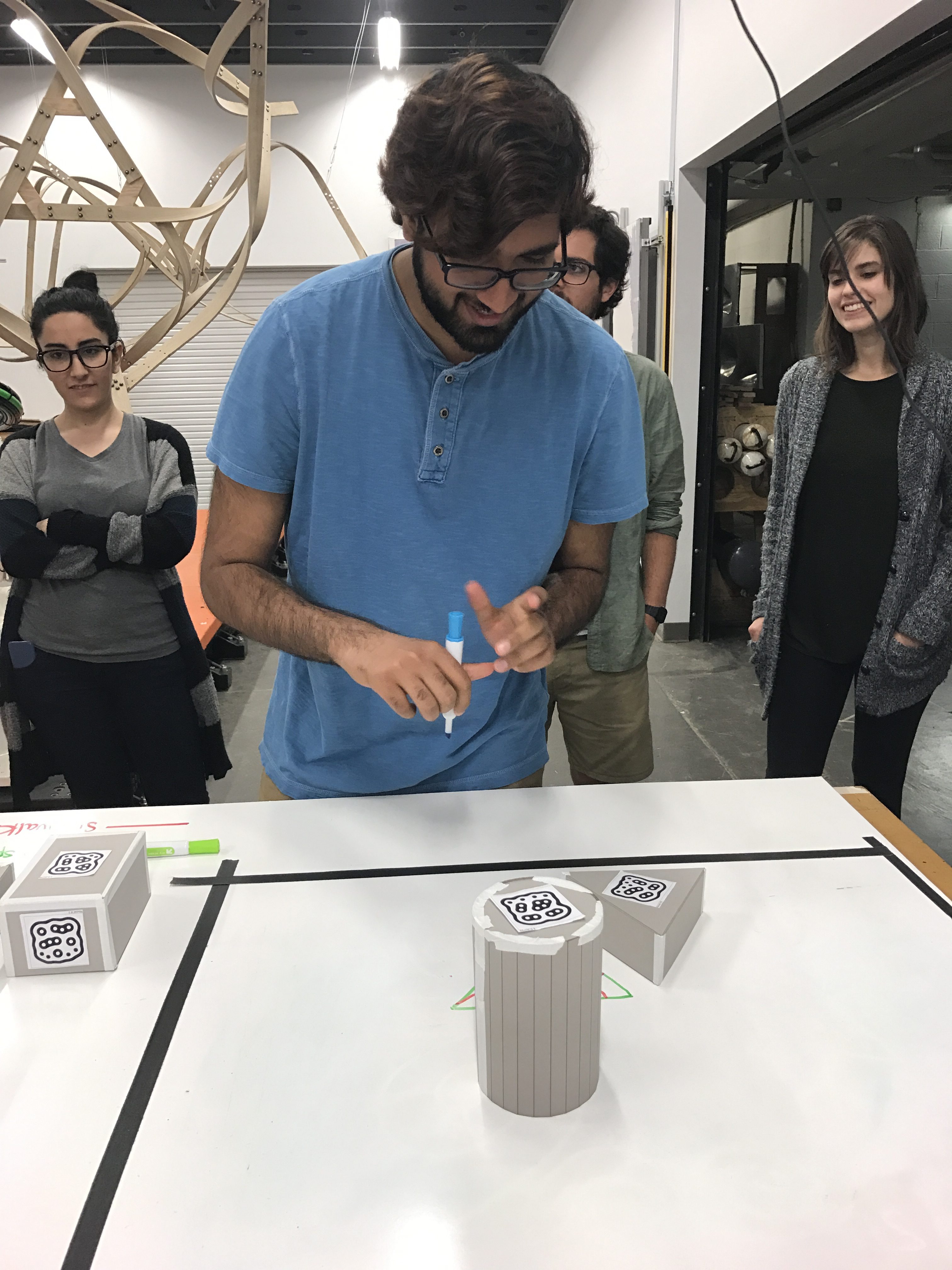
This project aimed to provide a playful method of designing a city block on a piece of cake using playful user input and a frosting-based output generated by an ABB robot and a Grasshopper script. On a plain white surface, a user arranges a set of cardboard building models, and using dry-erase markers draws walking paths, green spaces, and water bodies around the buildings. An image of the scene is captured from above and software identifies the position and orientation of the buildings and marker drawings. An ABB robot with a custom end-of-arm effector extrudes cake frosting in the form of the buildings and other drawn features. The model is scaled down by a factor of four and extruded onto the top of a flat cake, thereby making a cake city block.
Objectives
- Use fiducial-reading system to identify the orientation and position of known shapes and import their geometry into Rhino
- Use computer vision to capture colored paths drawn on whiteboard
- Pipe a city block consisting of legible frosted shapes generated from the above data onto a cake, using a custom end effector on an ABB industrial robot
Implementation
Motion and Depth Capture
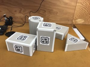
We laser cut models that represented buildings and attached uniquely numbered fiducial markers to each one. By attaching different markers to different faces, the boxes could be reoriented about their own axes to simulate differently proportioned buildings: whichever marker faced up was the one that was used for building identification.
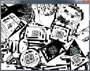
Building forms were scaled to have similar dimensions so as to increase likelihood of successful modeling of a city block. Choosing to build model buildings using regular volumes like a cylinder, rectangular prism, and triangular prism meant that the models were simple to design and construct. We used the reacTIVision system, version 1.5.1 (http://reactivision.sourceforge.net/), to generate and track fiducials, each of which was associated with predefined planes in Rhino.
Color and Vision Capture
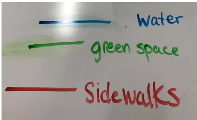
Sidewalks, water elements, and green spaces are represented by three different color whiteboard markers (red, blue and green respectively) These colors were chosen because they were intuitive, but also different enough to work effectively in computer vision.

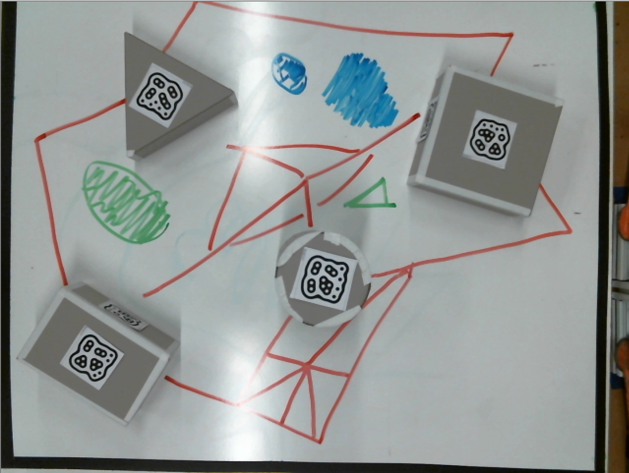
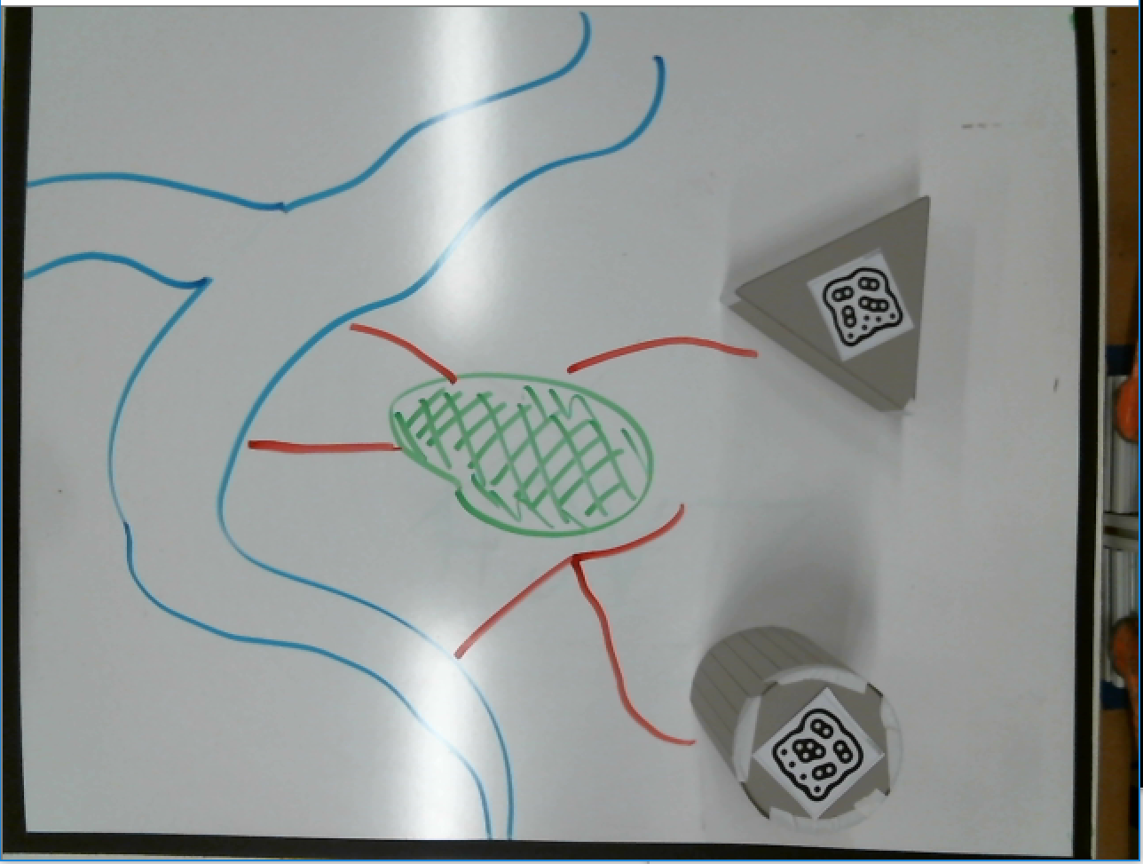
A webcam views the colored paths from above as they are drawn, and a python2 program using OpenCV3 installed via Anaconda (https://anaconda.org/menpo/opencv3). First the initial image is split into three images, each with only one color. Each image is then converted to grayscale, and the openCV drawContours function detects each path and saves a .data file of all points of each color.
Grasshopper then takes these data files and converts them into a tree, so each path is easily converted to robot code.
Frosting Extrusion System
Physical considerations and fabrication
We went through an iterative design process to create an end-of-arm effector for the ABB robot capable of extruding frosting using a commercially available frosting press (Wilton 415-0906 Dessert Decorator Plus).
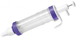
In order not to compromise food safety, we did not want to modify the frosting press in any way, for instance by replacing the pushing rod with our own rack and pinion. We chose a linear actuator to apply pressure to the frosting push rod; after comparing different models available, we settled on an 8″ travel linear actuator from Firgelli Automations, drawing up to 5A at 12V, capable of delivering 35 lbs. of force (part number FA-PO-35-12-8). Frosting, especially if it’s chilled and is being forced through a small cupcake frosting orifice, is actually quite resistive to flow and so at times the linear actuator may have been running at or near its rating.
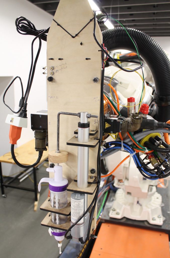
We developed digital models of the physical configuration of our end-of-arm assembly; we hand-drilled the base plate with holes corresponding to the mount points for the linear extruder and frosting press, and mounted custom lasercut parts to secure both of these parts. Mechanical plans, including Solidworks part files and DXF lasercut plans, are available in the project Github repository: https://github.com/robzach/cakeCity.
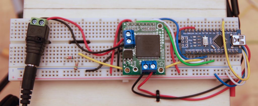
Electronics
Our end effector needed to receive properly synchronized control signals from the same source that was running the main motion process on the robot, so it was vital that the signals come through an onboard facility of the robot. Thankfully, our ABB IRB-6640 is configured with digital outputs that can deliver signals to the end effector. Using a simple voltage divider, the ABB’s 24V signal was brought down to a 5V signal appropriate to the logic level of an Arduino Nano. The control scheme was extremely simple: if the Arduino received a 10 millisecond high pulse, it would stop the extruder motor; if it received a 20 millisecond high pulse, it would continuously advance it at a given rate which we had previously determined empirically (and which was hardcoded into the firmware). We used a high-current H-bridge motor driver to deliver power to the motor (Pololu part 705, a carrier board for the VNH3SP30).
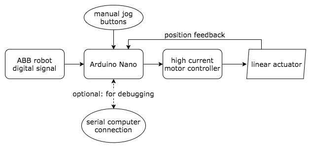
The motor advance was rate-controlled using position feedback from the linear actuator’s built-in multiturn pot; this proved to be important because of the nonlinear, resistive nature of the frosting load. For convenience, our end-of-arm tool also included momentary pushbuttons to jog the actuator in either direction. (The jog buttons were especially useful for deinstalling and installing the frosting extruder, which needed occasional refilling during robot operations.)
Firmware note
A single misread “start” or “stop” command could significantly disrupt the robot output, because until it receives a different command, the effector script is designed to continue in its current state indefinitely. For this reason, and because the Arduino often had a somewhat “busy” control loop that it would be running to keep the motor in the properly commanded position, we used an interrupt-driven scheme to read the widths of incoming pulses as reliably as possible. Here is the general logic of the ISR (interrupt service routine) that was called on every change in the pulseIn pin:
void readPulse(){
  static unsigned long startTime = 0;
  static uint8_t lastState = 0; // state of the pin last time the interrupt was triggered

  uint8_t readState = (PIND & (0b00000100)); // port access is quicker than digitalRead

  if (readState != lastState) {
    if (readState) startTime = micros(); // if just went high, start timer
    else {
      diff = micros() - startTime; // if just went low, stop timer and count difference
      // use "diff" to drive motor outside of ISR
    }
    lastState = readState;
  }
}
Note that the global variable diff should be declared as a volatile since its value will be affected by the ISR. The interrupt-driven model is a superior scheme to using the Arduino’s built-in pulseIn() function, because that function is blocking: if left in its default configuration it can hang for up to 1 second while waiting for the second half of an already-begun pulse to complete. Firmware is available on the project Github page, as linked above.
ABB Rapid Code Generation
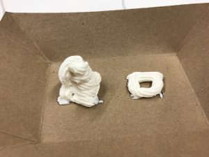
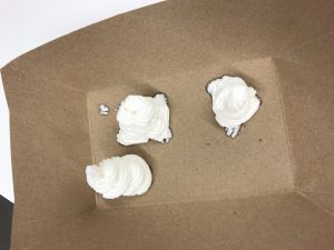
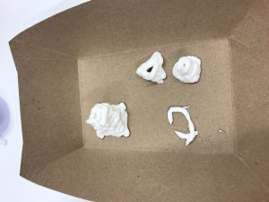
Once the building and colored drawing path data was acquired, it was scaled down by a factor of four to fit on the cake. The reacTIVision and OpenCV data were interpreted separately and were in two different files before they were sent to the robot. While it was clear that the color capture data was meant to be translated into two-dimensional polylines with subdivisions, generating the buildings would be a challenge as they were meant to be a series of offset rings of frosting to be stacked in three-dimensional figures. Before deciding how to script the offset lines, we manually frosted buildings to see which pattern would be the most legible. We settled for separating the polygonal geometric figures into line segments with their own entry and retract points instead of compiling them into a typical cupcake swirl since we assumed that frosting could not turn a sharp corner.
A series of pathways was then generated in Grasshopper to emulate the most effective pattern that we had piped by hand. These pathways were initially polylines, which were then separated into line segments or individual curves. The overall forms are slightly tapered to allow the frosting rings to sit on each other without falling over.

These paths were then divided, generating planes at their endpoints and in the cylinder’s case, midpoints.
After carefully separating each geometric input into classes (boxes, prisms, cylinders, polylines), we input the planes into a HAL code template that would create a series of movements and frosting extrusion commands to be written into Rapid code. Each plane became a command for the robot to move to a certain position on the table. Then, commands for starting (ToolOn) and stopping (ToolOff) the flow of frosting were methodically woven into the series of planes so that the machine would extrude frosting at the right moments to generate lines on the cake. In order to organize the paths, the code was partitioned so that every item in a particular group would be extruded before moving onto the next group. The paths were frosted in this order: box, prism, cylinder, then polyline.
Outcomes
We succeeded in creating a frosting apparatus that could extrude frosting on command. We also successfully captured image data from reacTIVision and OpenCV to be converted to ABB Rapid instructions, resulting in code that placed frosting on a cake in a pattern that we correctly generated. What had been gathered of the color data was smoothly represented by the frosting patterns.
However, we were not able to create scaled building figures from frosting. There had been so many planes (at least 2,000 per building!) generated from the desired offset pattern that the Grasshopper script crashed each time we attempted to convert the data to HAL code. We had to settle for extruding a single frosting ring for each figure, so we had building footprints instead of full buildings. Additionally, the color capture data for our demo was incomplete because shadows had been cast over the lines. While the machine extruded frosting in the patterns that we intended, excess frosting was pushed out even when ToolOff commands had been sent to the robot. The shapes were illegible because of this.
Contributions
Lissa worked on OpenCV/Python color capture, created the SolidWorks model of the plate to be attached to the robot, and compiled and edited the video.
Victoria worked on ReacTIVision/Grasshopper geometry capture, created the building model inputs, and compiled the two image capture Grasshopper scripts into a single file to generate the ABB Rapid code.
Zach (“Robert”) focused on frosting extruder design, fabrication, electronic implementation, and firmware development.
Related Works
Dinara Kasko’s architectural pastries: http://www.dinarakasko.com/
Unibot Cake Decorator: https://www.youtube.com/watch?v=xdLIRwdCSyM