INTRODUCTION
For the final project in 60-223: Introduction to Physical Computing, each group was tasked with developing a project to assist the life of a client living with a disability. Our client, Amy Shannon, is severely paralyzed in numerous parts of her body including her hands. An avid creative at heart, Amy expressed to us during our interviews that she would love to be able to participate in creative activities, including tasks that require extensive manual dexterity like drawing and painting. In the past, she’s tried to use a painting device called a mouth stick, but has found it rather uncomfortable and inhibiting. Our group fixed in on developing a suitable system that can provide an experience as close to actual hand painting as possible in the form of a painting rig and a control mechanism capitalizing on our client’s available motion ranges. Given the restrictions of remote learning, we were unable to produce a final physical product, but this would certainly be an exciting next step!
WHAT WE BUILT
Our Art Enabler project allows the user to paint using a pair of wireless controllers and a mechanical painting rig that can be mounted onto a painting easel. To best explain how this painting experience is possible, we will explore each of the 3 Art Enabler project components: the controllers, the painting rig, and the interface code.
THE CONTROLLERS
There are two wireless controllers within our project system that act as the primary user interface – the Pressure Controller and the Primary Controller. The Pressure Controller has a simple handle attached to a slider. Moving this slider can control the Z-axis movement of the drawing utensil, making it either be closer or further away from the canvas to let the user have a wider possible range of mark-making. The Primary Controller has a joystick that can be shifted to make the drawing utensil move around the canvas. It also features a clamp that allows the controller to be attached to an average wheelchair armrest and a telescoping neck that lets the user move the controller’s position up or down to better accommodate their arm.
Both controllers also feature a power switch that the user can toggle to turn the device on or off to save battery life!
THE PAINTING RIG
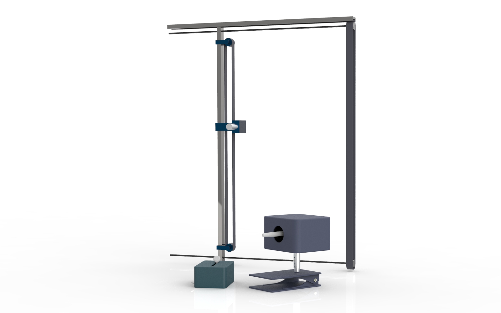
The mechanical painting rig can be attached to the user’s painting easel and holds the desired drawing utensil. It has two belts to control the X- and Y-axis position of the utensil to allow the user to draw what they would like! When they move the controller, the motors on the rig make the utensil holder move up, down, left, and right accordingly. The utensil holder itself also features a spring, which pressure changes based on the input of the Pressure Controller, allowing for the drawing utensil to move closer or further from the canvas.
INTERFACE CODE
This code is what makes the magic happen! Within each of the physical components, there is an Arduino and a radio module, which allows all of them to communicate with each other to send and receive informational inputs. This code takes the positions of the joystick and the slider and then sends these inputs to the rig, which adjusts its position based on these inputs.
By combining all three of these components, the user can paint or draw without needing to pick up a paintbrush or pend themselves!
A quick animation to show how moving the joystick on the right controller moves the painting rig
All three components of the Art Enabler
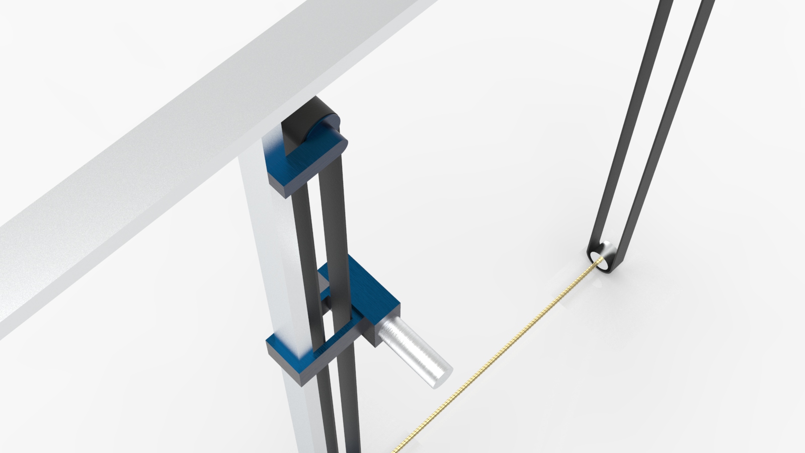
The painting rig with two belts to control the X and Y-axis movement of the drawing utensil
How the painting rig may look like when in use on an easel
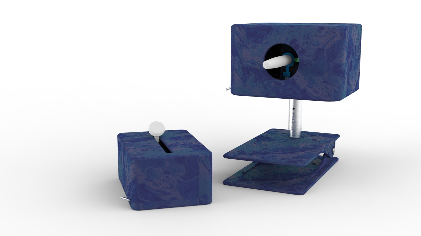
The two controllers: On the left, the Pressure Controller can manipulate the Z-axis position. On the right, the Primary Controller can change the X- and Y-axis position. The Primary Controller can clamp onto a standard wheelchair arm.
As we were unable to create this project physically, we cannot show a video of the interactions that take place within the final project scope. Therefore, we will describe the overall interactions here to better explain the concept in context. This system requires some assisted setup before it can be operated, but, once it is set up Amy can use it almost totally independently from there on out. To complete this setup, someone (most likely either Amy’s aid or parent) must attach the painting rig to the intended drawing easel, place the drawing utensil in the holder, and place the controllers by Amy’s wheelchair or on them, using the integrated clamps. After the setup is complete and Amy decides that she would like to draw, she can position herself in front of the easel (however close or far away that she would like) and turn on both of the controllers by flipping the power switch. To start to paint, she can push the Pressure Controller’s slider until the utensil touches the canvas at the desired pressure. Then, she can move the joystick to move the drawing utensil and begin to make her marks. The movement of the rig is mapped to the velocity of the joystick’s movement (a common practice in many video games, so hopefully it is a fairly familiar interaction) so that if Amy moves the joystick a little to the left, for example, the rig will start to move slowly towards the left until the joystick returns to the center or changes direction. If she moves the joystick very much to the left, the rig will then move quickly in that direction until the joystick returns to the center or changes direction. The joystick has a spring attached to it so that if she lets go of it at any time, it will snap back to the center and stop the rig from moving further. When she’s happy with the stroke she made, to make a new mark, Amy can use the Pressure Controller to lift the drawing utensil off of the canvas and then the Primary Controller to move it to a new position.
This process of lifting and moving utilizing the two controllers should allow Amy to draw what she would like and when she would like after a little practice to familiarize herself with the controls and movements. Hopefully, after creating a few art pieces for practice, these interactions will become more fluid and natural to allow for greater artistic expression without any need for a mouthstick!
HOW WE GOT HERE
While we came up with the idea for the Art Enabler fairly quickly after our first interview with Amy, the details and interactions of it have evolved tremendously as we continued to develop the project. At the start, we were aiming to have a single, arm-mounted controller that allowed Amy to move her arm and have that be the input that would control the mechanical rig that would be able to move along the X- and Y-axis.
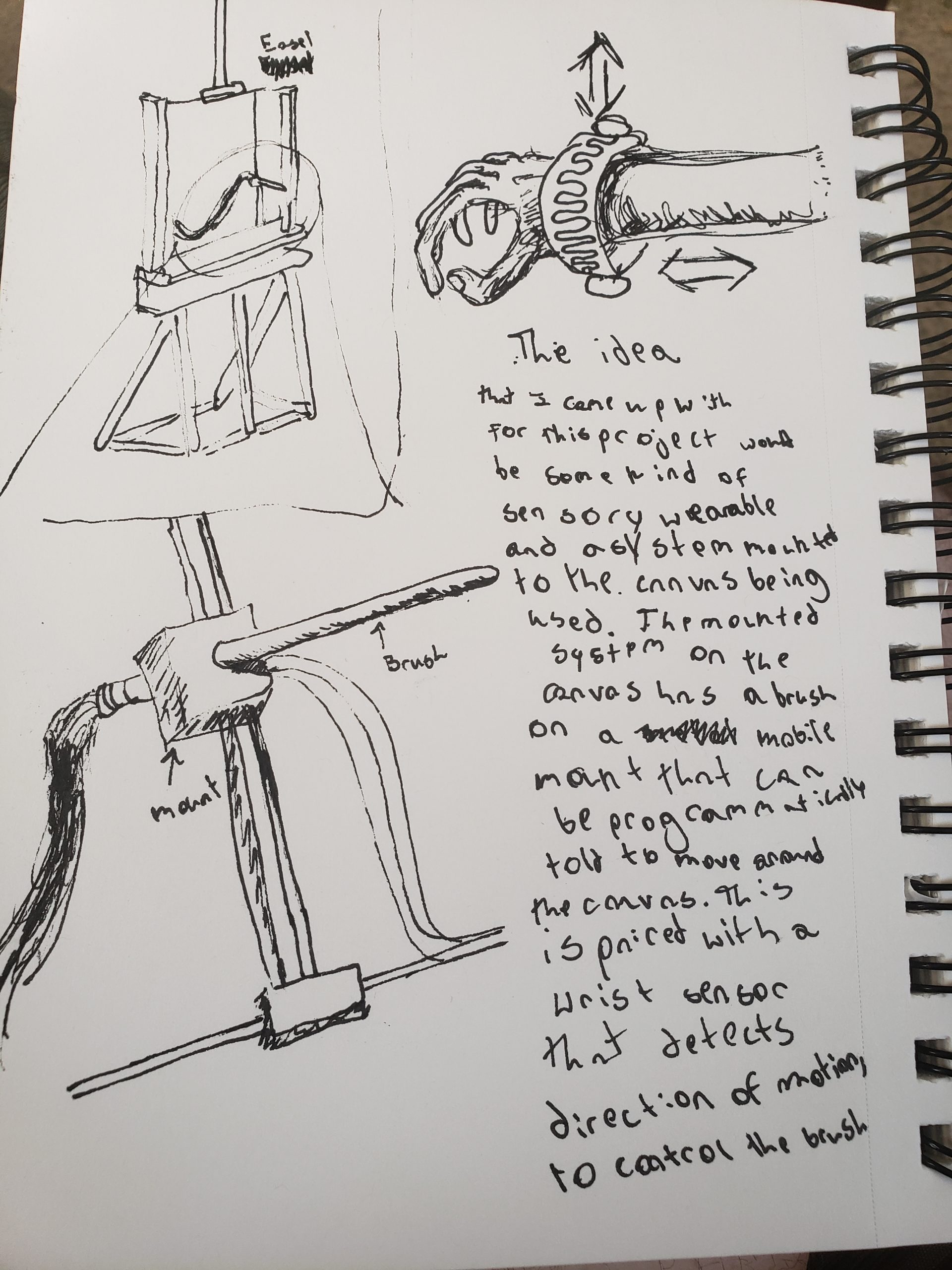
Initial concept sketch
An example of our first interaction concept
However, after talking to Amy again, we realized that it would be tiring for her to hold her arm up for long enough to create a painting. Furthermore, as we continued to flesh-out our concept further and began to explore different types of sensors that could make a user input wirelessly control the painting rig, we realized that an arm-mounted controller wouldn’t provide the desired smooth drawing experience we were aiming for (this is, even if we could get such a device to work using IR sensors). Amy also expressed concern about being able to control the pressure of her mark-making like she would be able to achieve with a mouth-stick.
In light of these new insights, we pivoted our concept, deciding we needed to rethink the controllers and also the rig’s range of movement.
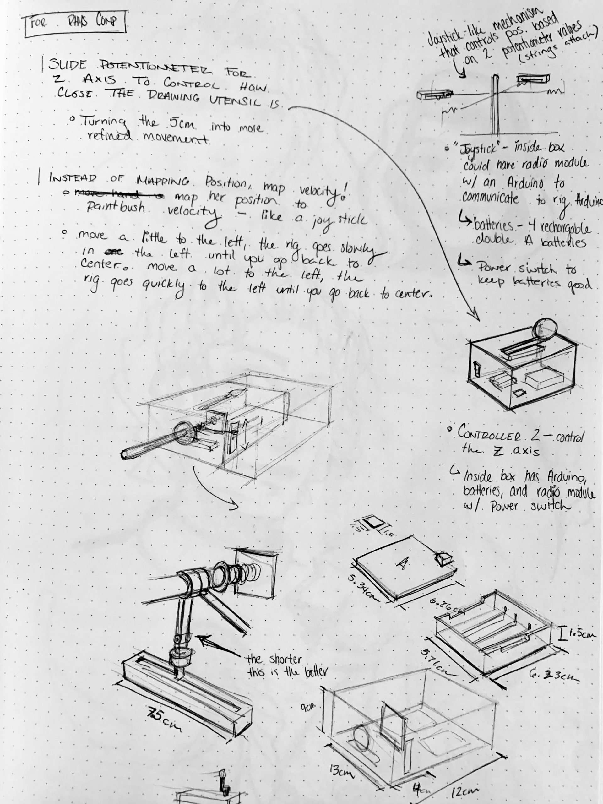
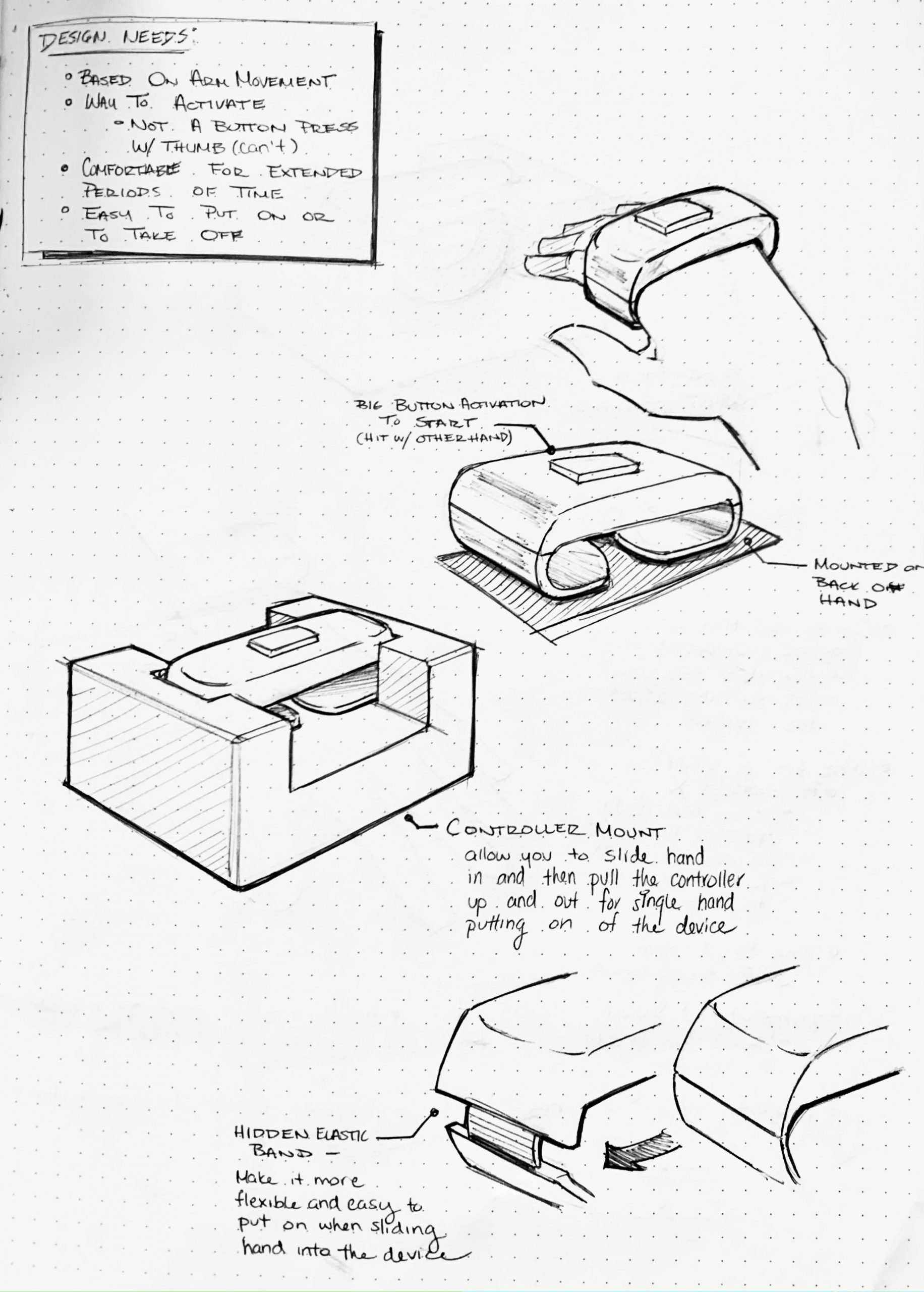
Sketch Page of brainstorming new types of controllers and interactions
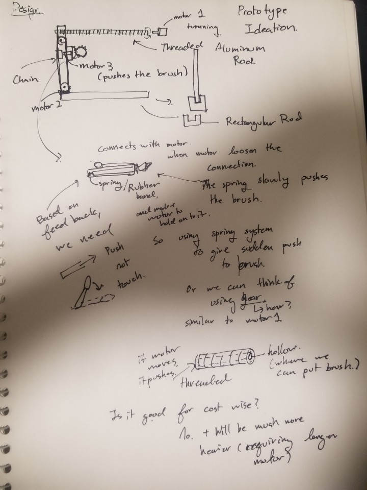
Ideation of Prototype and detailed plannings for each Mechanical Sections
For the controllers, we decided to use potentiometer values to control the axis positions. We had to devise a way to create our own version of a joystick – which would resemble a paintbrush – in accordance with this, along with thinking about how to design the form of the controllers in order to best suit Amy’s range of motion (we would have changes in this area if we are to continue this project, but that will be touched upon in the Reflections and Lessons Learned section of this documentation page). To make the wireless communication work, we employed to use of 3 Arduinos – one in each project component – and 3 RF transceivers which could be utilized to have the Arduinos “talk” to each other.
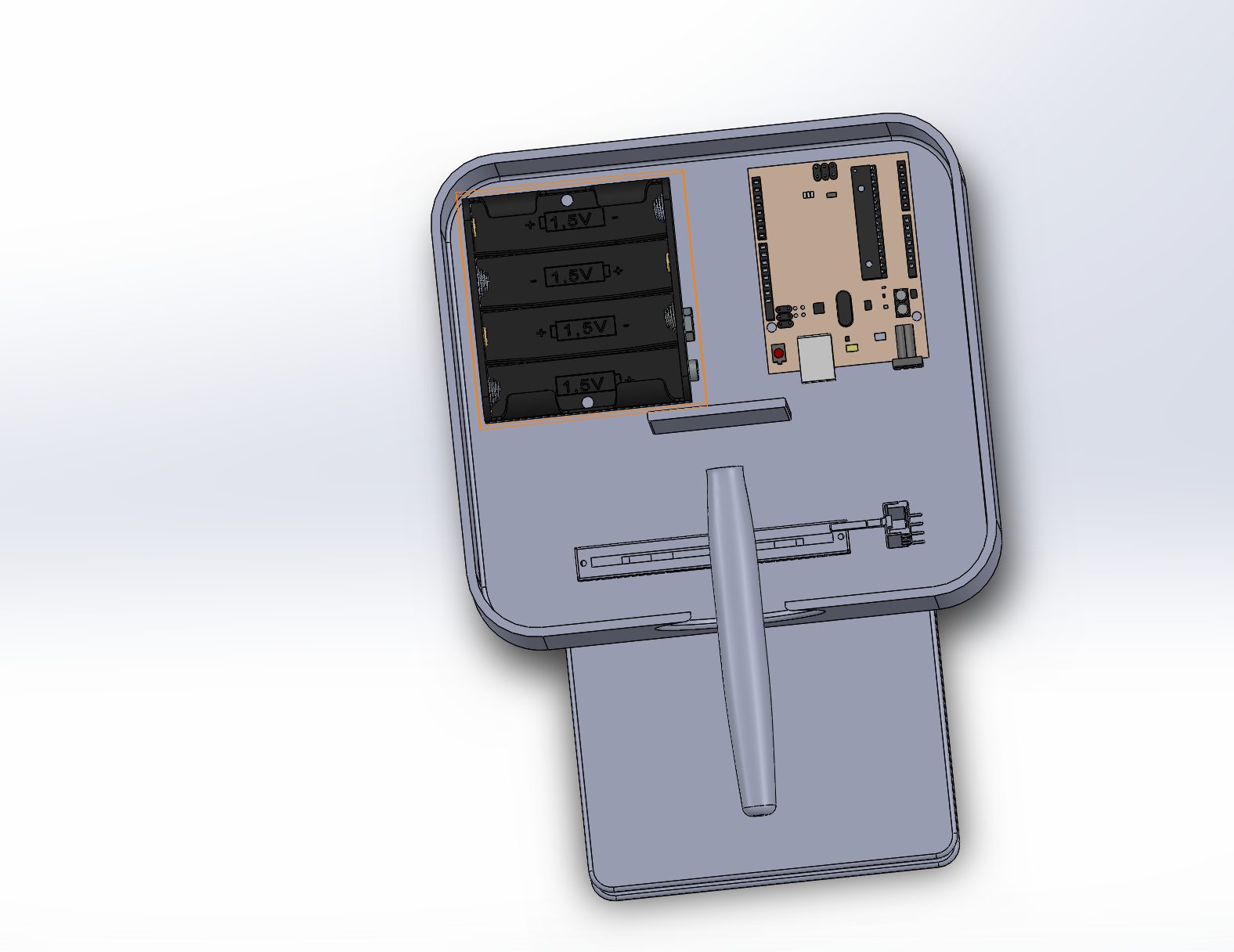
Working on the controller’s CAD to ensure that all components could fit into the exterior frame and that the joystick could move the two slide potentiometers
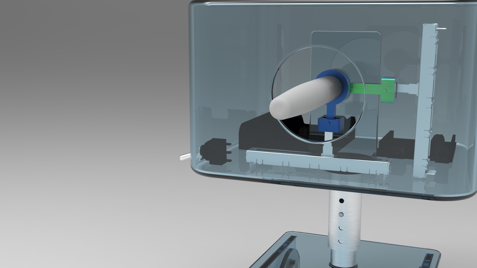
Working on the controller’s CAD to ensure that all components could fit into the exterior frame and that the joystick could move the two slide potentiometers – clear view of the controller
For the mechanical rig, we decided that we needed to accommodate for some type of pressure sensitivity. As we were still working through the problem of how to lift the drawing utensil off and onto the canvas to better replicate a typical drawing experience (which isn’t only one continuous line), we decided to integrate these two issues into one solution: the Pressure Controller and adjustable spring within the rig’s drawing utensil holder. These would allow the user to move the utensil as close to or as far away from the canvas as they would like, allowing for them to “lift” the utensil off the canvas or draw fainter stokes.
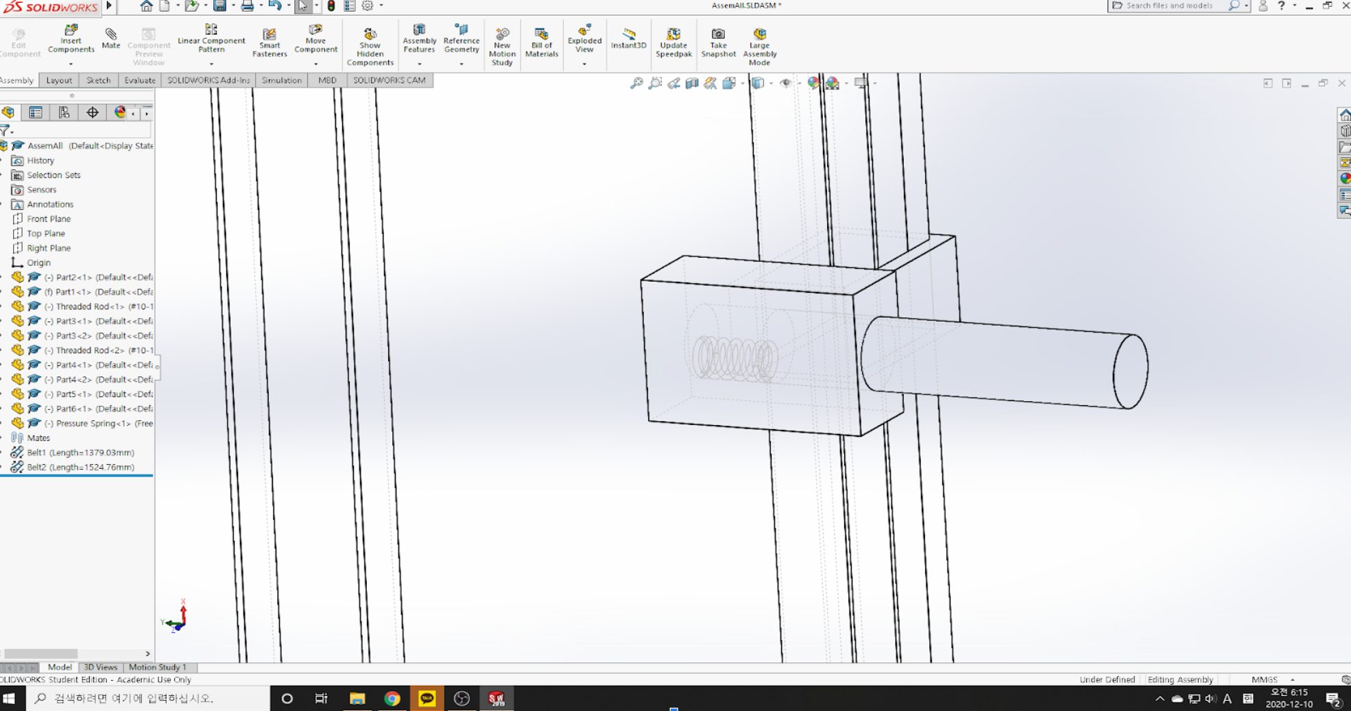
The rig’s new spring
We also worked closely with our professor, Zach, to iterate on the mechanical rig’s CAD to ensure that there was smooth, discrete movement along every axis. With our first rig design, which only featured one belt, when Amy moved the controller, the rig would move smoother and quicker in one axis compared to the other. After talking with Zach about this issue that came to light, we again pivoted towards our final two-belt design, with each driven by its own motor. One of these belts would allow the rig to move along two threaded rods to go left and right. The other drives the up and down motion of the device.
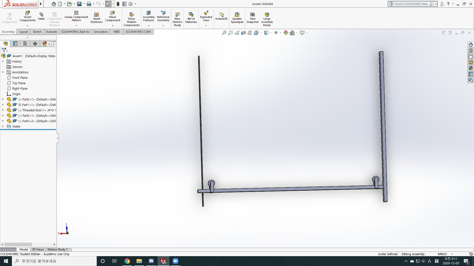
First Rig Design
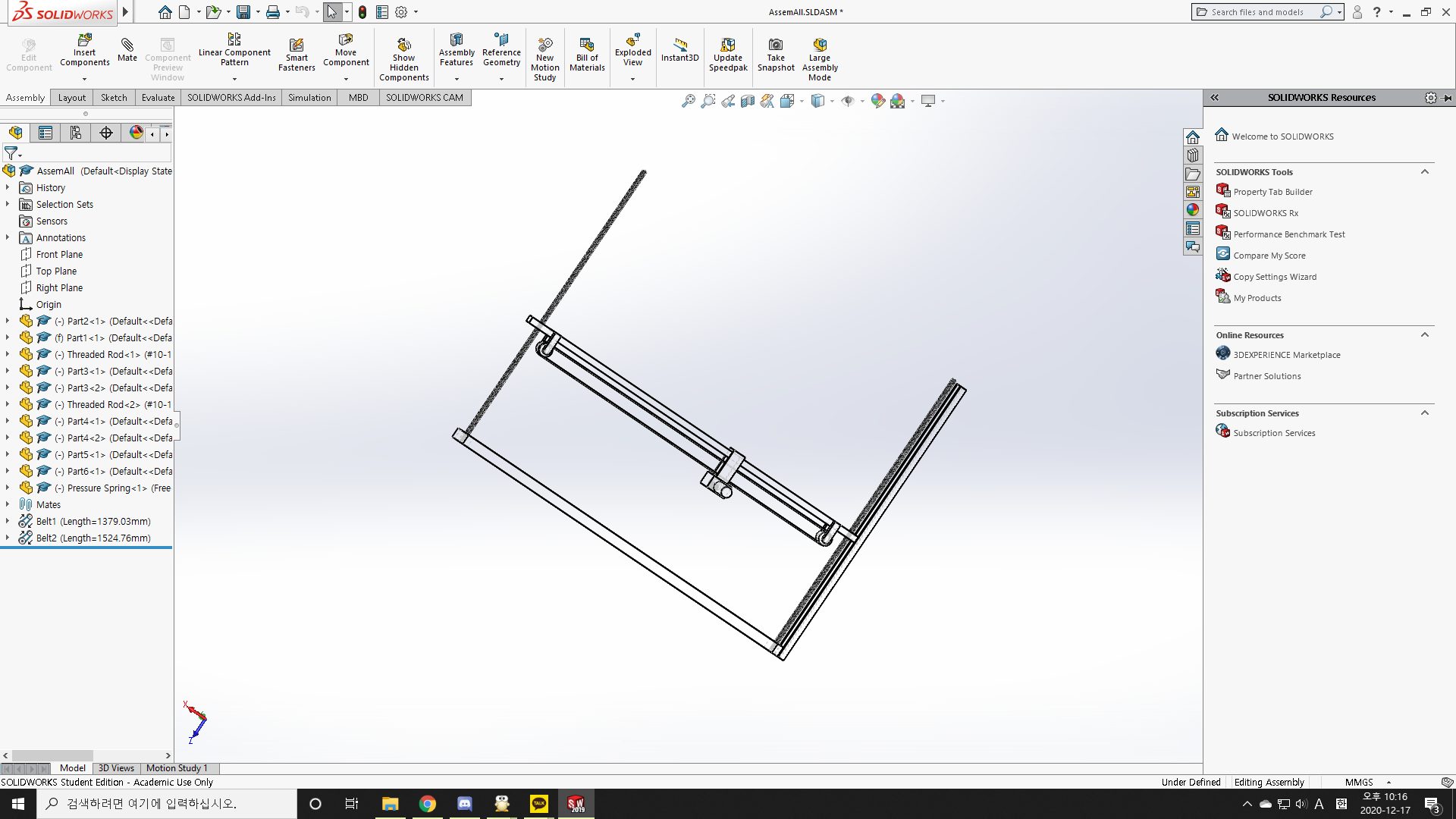
Final Rig Design
Once we figured out our components and sensors, it was time to write the code to bring it all together. However, we discovered that it is hard to write code without being able to physically test its viability. Utilizing TinkerCAD, we were able to make some interaction mock-ups to test our ideas but, in the end, this part of our project has the most theoretical functionality.
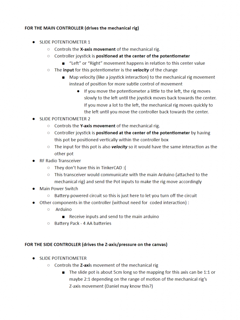
A document detailing the different electronic components and what each should do to ensure proper alignment with the physical components and the coded components
REFLECTIONS and LESSONS LEARNED
After the final presentation, we got a lot of positive feedback from other people. Someone said this would be a great idea and the most marketable product out of the presented items. However, to produce this as a market product, the rig section seemed a little unstable compared to the controller section. This might have happened due to less supporting structure for the rig connected to the canvas. Therefore, if we have a little more time with this final project, we would have built and designed the supporting structure section of our machine.
Also, working remotely with other people created a lot of communication issues among group members. We mostly used zoom and text messages to communicate with each other about our project’s progress. We also used class time to divide our works and share comments between our original works. However, we did not have a chance to combine all of our works until the day before the actual presentation. Also, it took several hours to receive a response from team members after sending a text message. Fortunately, we had enough time to discuss our own products and share ideas with team members but we had a lot of communication issues between team members.
Lastly, working with Amy provides more insight into different types of clients. Through the interview, we were able to learn what kind of hardship do paralyzed people face in daily life. For instance, Amy was having a hard time holding some items due to her spine injuries. To draw pictures, she used a special mouthstick to hold brushes. However, this action made her jaws tedious and limited her drawing hobbies. Through this project, we have suggested some possibilities she might able to use to solve her uncomfortable situation.
TECHNICAL DETAILS
Code
/* Art Enabler Prelim Code */

// Preface to the code shown here:
/* First and foremeost, this code is intended to drive a system
 * that can't realistically be assembled in TinkerCAD.
 * As a result, there is a lot of 'hacking' going on to
 * to at least produce the requisite result for the project.
 *
 * The reason that it can't be assembled in rather simple -
 * none of the required components exist in TinkerCAD,
 * and the closest availabe replacements aren't nearly wieldy
 * in the TinkerCAD environment.
 *
 * All single lines of code in multiline style comments are
 * for operations not supported in TinkerCAD
 *
 * | PINS |
 * POSPIN_X : Reads sensory data to set internal X position
 * POSPIN_Y : Reads sensory data to set internal Y position
 * POSPIN_Z : Reads sensory data to set internal Z position
 *
 * PX : Workaround pin to directly send X pos info to motor
 * PY : Workaround pin to directly send Y pos info to motor
 * PZ : Workaround pin to directly send Z pos info to motor
 */

// Radio control code adapted from:
// https://create.arduino.cc/projecthub/MisterBotBreak/how-to-communicate-using-433mhz-modules-9c20ed

// Smoothing code adapted from:
// https://courses.ideate.cmu.edu/16-223/f2020/text/code/FilterDemos.html

// Libraries
/* #include "VirtualWire.h" */

// Pin assignment
const int POSPIN_X = A0;
const int POSPIN_Y = A1;
const int POSPIN_Z = A2;

/* const int TRANPIN = 2; */

// Following pins are used for sending data to the "stepper" motor
// as a TCAD workaround
const int PX = A3;
const int PY = A4;
const int PZ = A5;

// Global settings
/* In a world where this is being built, it would be worthwhile
 * to add some additional hardware components to adjust settings
 */
static float resolution = 100; // Mapping resolution, gets around map type constriction

static float scale_z = .1; // Scales motion off canvas
static float scale_x = .001; // Scales planar motion
static float scale_y = .001;

static float min_x = 0.0;
static float max_x = 1.0;

static float min_y = 0.0;
static float max_y = 1.0;

static float min_z = 0.0;
static float max_z = 1.0;

static float pos_x;
static float pos_y;
static float pos_z = 0; // Corresponds to off canvas

// These variables were shoddily taped on after realizing TinkerCAD
// is insufficient:
static float prev_x = 0;
static float prev_y = 0;
static float prev_z = 0;

void setup()
{
  // Default to center
  pos_x = max_x / 2;
  pos_y = max_y / 2;

  pinMode(A0, INPUT);
  pinMode(A1, INPUT);
  pinMode(A2, INPUT);

  pinMode(2, OUTPUT);

  // Setup radio transmission
  /* vw_setup(2000); */

  // Patch for TCAD
  pinMode(PX, OUTPUT);
  pinMode(PY, OUTPUT);
  pinMode(PZ, OUTPUT);
}


// Smooths input based on a previous value
float smoothing(float input, float prev, float coeff=0.1)
{
  float difference = input - prev;  // compute the error
  prev += coeff * difference;       // apply a constant coefficient to move the smoothed value toward the input
  return prev;
}


// Used to clamp ranges
float clamp(float input, float rangemin, float rangemax) {
  float value = max(input, rangemin);
  value = min(value, rangemax);
  return value;
}


// Obtains and maps a given pin, assuming the input is a position
float map_pin_read(const int PIN)
{
  int reading = analogRead(PIN);
  float map_val = map(reading, 0, 1023, (int) -resolution, (int) resolution) / resolution;
  return map_val;
}


float update_pos(float pos_v, float min_v, float max_v, float scale_v, const int POSPIN_V)
{
  float dv = scale_v * map_pin_read(POSPIN_V); // Get pin input and map to a val
  pos_v = smoothing(pos_v + dv, pos_v);
  pos_v = clamp(pos_v, min_v, max_v);
  return pos_v;
}


void update_poses()
{
  pos_x = update_pos(pos_x, min_x, max_x, scale_x, POSPIN_X);
  pos_y = update_pos(pos_y, min_y, max_y, scale_y, POSPIN_Y);
  pos_z = update_pos(pos_z, min_z, max_z, scale_z, POSPIN_Z);
}


void transmit_pos() {
  float poses[3] = {pos_x, pos_y, pos_z};
  /* vw_send((byte *) poses, 3 * sizeof(float)); */
  /* vw_wait_tx(); */
}

// In all honesty these functions could absolutely be broken,
// but it exists only as a compatability measure for TinkerCAD
// after having written other code intended for a real system.
int SPEED_COMP(float old_val, float new_val, float v_max) {
  float res = resolution;
  float diff = new_val - old_val;
  return map(diff, 0, res * v_max, 0, 1023 * res) / res;
}

// Compatability function to circumvent lack of IR receivers
void TCAD_COMP() {
  // Calculate difference between new val and old for speed calc
  int X_SPD = SPEED_COMP(pos_x, prev_x, scale_x);
  int Y_SPD = SPEED_COMP(pos_y, prev_y, scale_y);
  int Z_SPD = SPEED_COMP(pos_z, prev_z, scale_z);

  // Store previous values
  prev_x = pos_x;
  prev_y = pos_y;
  prev_z = pos_z;

  analogWrite(PX, X_SPD);
  analogWrite(PY, Y_SPD);
  analogWrite(PZ, Z_SPD);
}

void loop() {
  delay(20);
  update_poses();
  /* transmit_pos(); */

  /* BELOW INCLUDED FOR TCAD COMPATABILITY */
  TCAD_COMP();
}
Schematic and design files
Controller CAD Google Drive Link
https://drive.google.com/drive/folders/19qEuezqMGOownMQQUnk6_TxUlWhi9VCs?usp=sharing
Rig CAD Google Drive Link
https://drive.google.com/drive/folders/1j7hFiTiPuqBnq-hJt8R1rr6JDi5l3Oel?usp=sharing