1. Introduction
For the final project of our Physical Computing class, we were tasked with building an assistive device specifically catered towards one person with disabilities in partner groups. Our group was partnered with a client named Brenda, and upon learning about the circumstances of our assignment, we initially interviewed her to get a better sense of her disabilities and brainstorm ideas of potential assistive technologies that could assist her in her daily life.
More details about our interview results can be found here: https://courses.ideate.cmu.edu/60-223/f2020/work/interview-with-brenda/
After ideating, revising, and finally settling on an idea, and due to the remote nature of our class, we individually created prototypes to test various functionalities of our idea, more details of which can be found here: https://courses.ideate.cmu.edu/60-223/f2020/work/team-brenda-2-prototype-documentation/
2. What We Built
Our final project assistive device is a danger sensor, akin to the back dash cams that cars possess, meant to help Brenda detect any obstacles or fallen objects behind her out of visibility due to her chair. More specifically, our device takes advantage of distance sensors mounted behind Brenda’s assistive chair to sense for any inconsistencies behind her and alert Brenda of any obstacles through a vibration and a light visualizer to gauge the position and distance of those items sensed behind her.
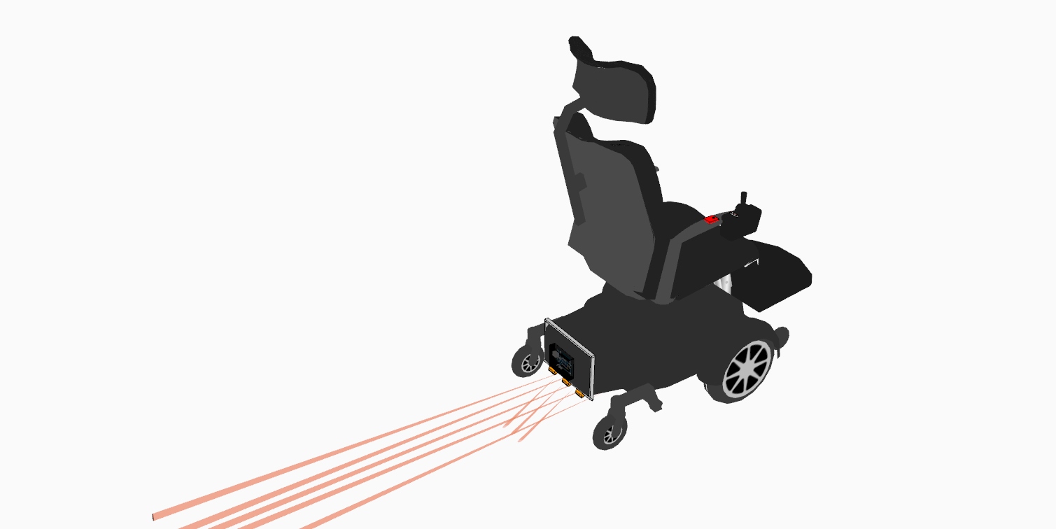
IR Option (perspective)
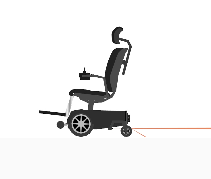
IR Option (Side)
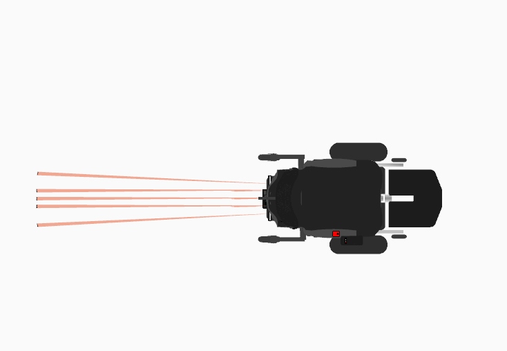
IR Option (Top)
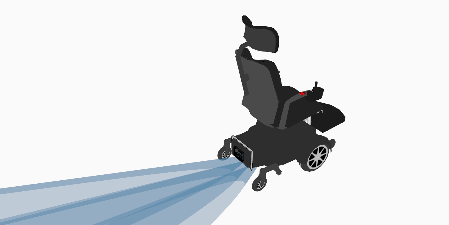
Ultrasonic Option (Perspective)
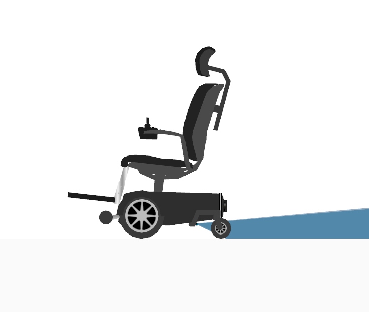
Ultrasonic Option (Side)
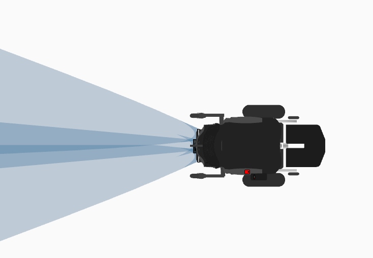
Ultrasonic Option (Top)
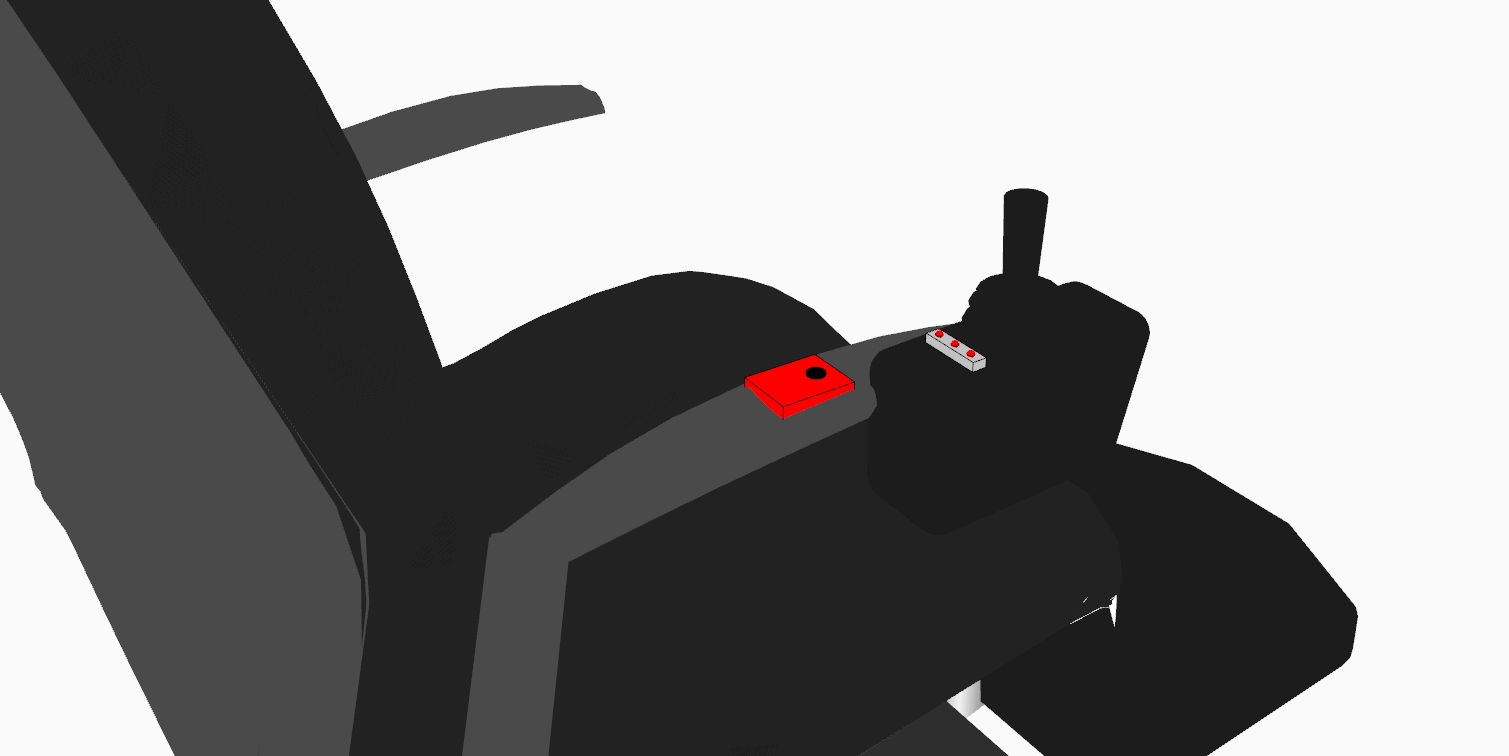
Communication Module (Vibrator + Three LED’s)
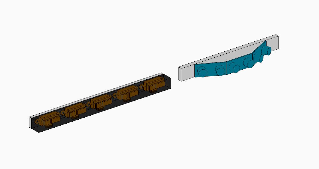
Left: Mounting for IR sensors Right: Mounting for US sensors
3. How We Got Here
Our project development could be largely broken down into five parts following the initial interview with Brenda: Initial Design Idea, Pivoting Part, Prototyping, Research and Design Development.
- Initial Design Idea
We had the first interview with Brenda to gauge what kind of trouble that she has in her daily life and to brainstorm ideas for solutions. She presented us with a multitude of problems that we could try to address. Only problem was that most of them seemed addressable only through mechanical means rather than electrical. (Full interview documentation could be found here)
Out of the several different ideas that she gave us, we decided to address her problem with the current footholders she has. These footplates are hard for her to reach down – and she also has a problem of not being able to fold them up herself. She always needs an assistant to do so, which made her wish the process could be automated, and that she doesn’t have to lift her feet every time.
As an initial design, we decided to develop an automated foot-holder system that uses the IR remote control and a telescoping system that would expand and contract at her wish.
However, we soon realized that the solution would include a mechanical system that would be too hard for us to solve. The system itself would be hard to design, and we would have to prove that it would hold the weight of her feet. These things were way out of scope of our capabilities. We had to make a choice here to abandon this idea and pursue a different one.
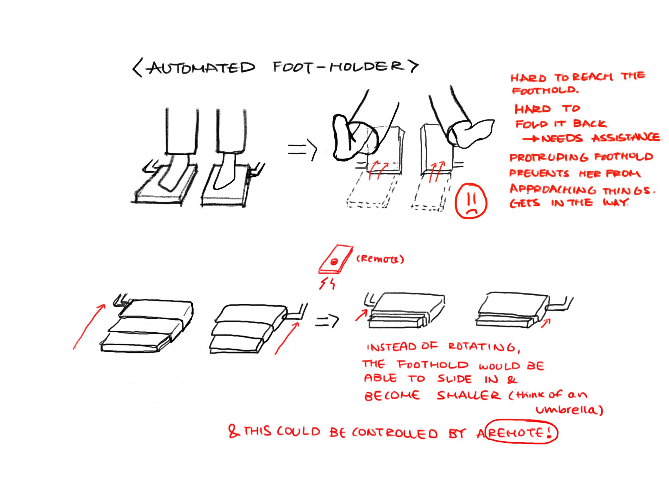
Sketch describing our initial design idea – an automatic foot holder!
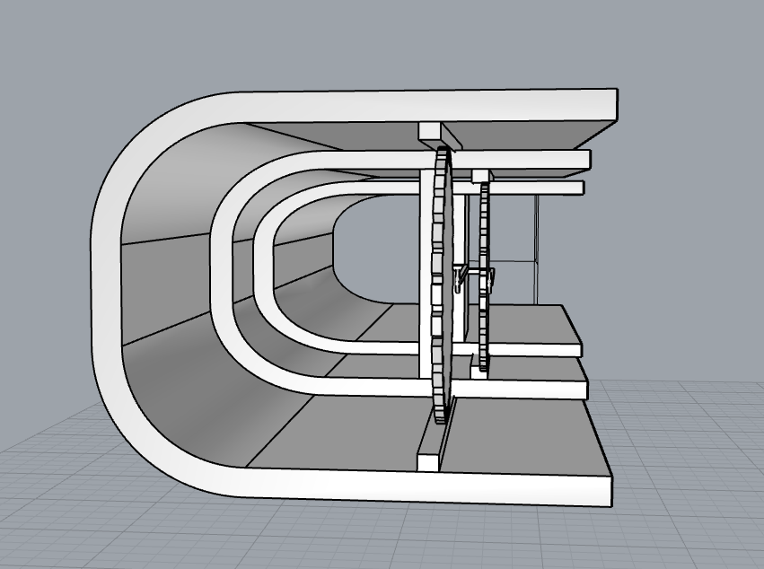
Telescoping Mechanism (front, folded)
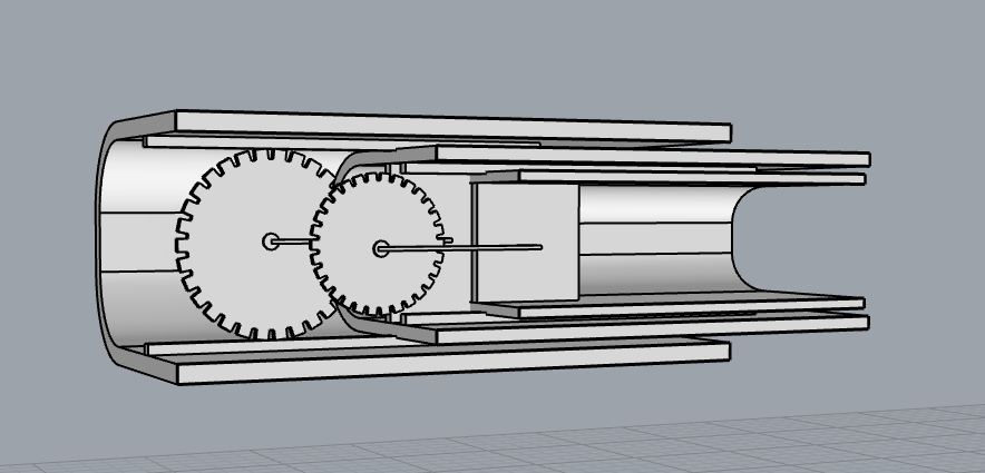
Telescoping Mechanism (side, folded)
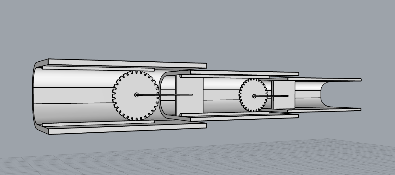
Telescoping Mechanism (side, unfolded)
- Pivoting Part
After realizing that the initial idea wouldn’t work, we decided to hold a second interview with Brenda. Fortunately this time, after speaking with her and letting her know that we needed a solution that includes electrical components rather than mechanical, we were able to get quite a few new ideas that fit the scope of this project. (Full second interview documentation could be found here) Out of the few options that we had, we decided to address her problem of having difficulties seeing behind her because of the fixed headrest and the immobility of the left side of her body. She’s just learned to be careful when looking back or moving backwards. We thought of making something of a car backcam that would let her know of what’s behind her. But instead of a camera, we decided to use a set of ultrasonic sensors to sense the objects behind her. As an output system, we decided to use a set of LEDs and a speaker to let the user know of the proximity to the objects.
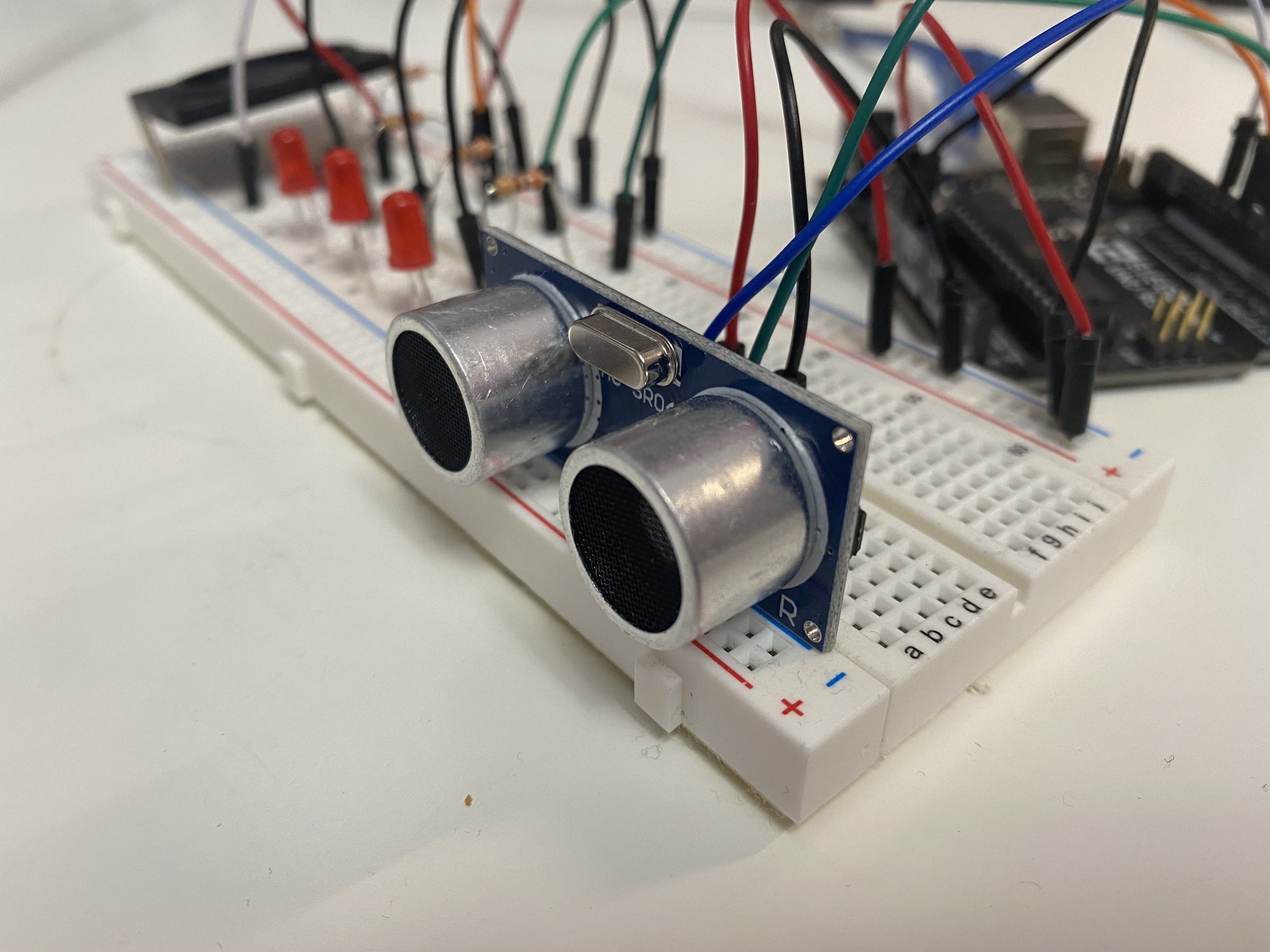
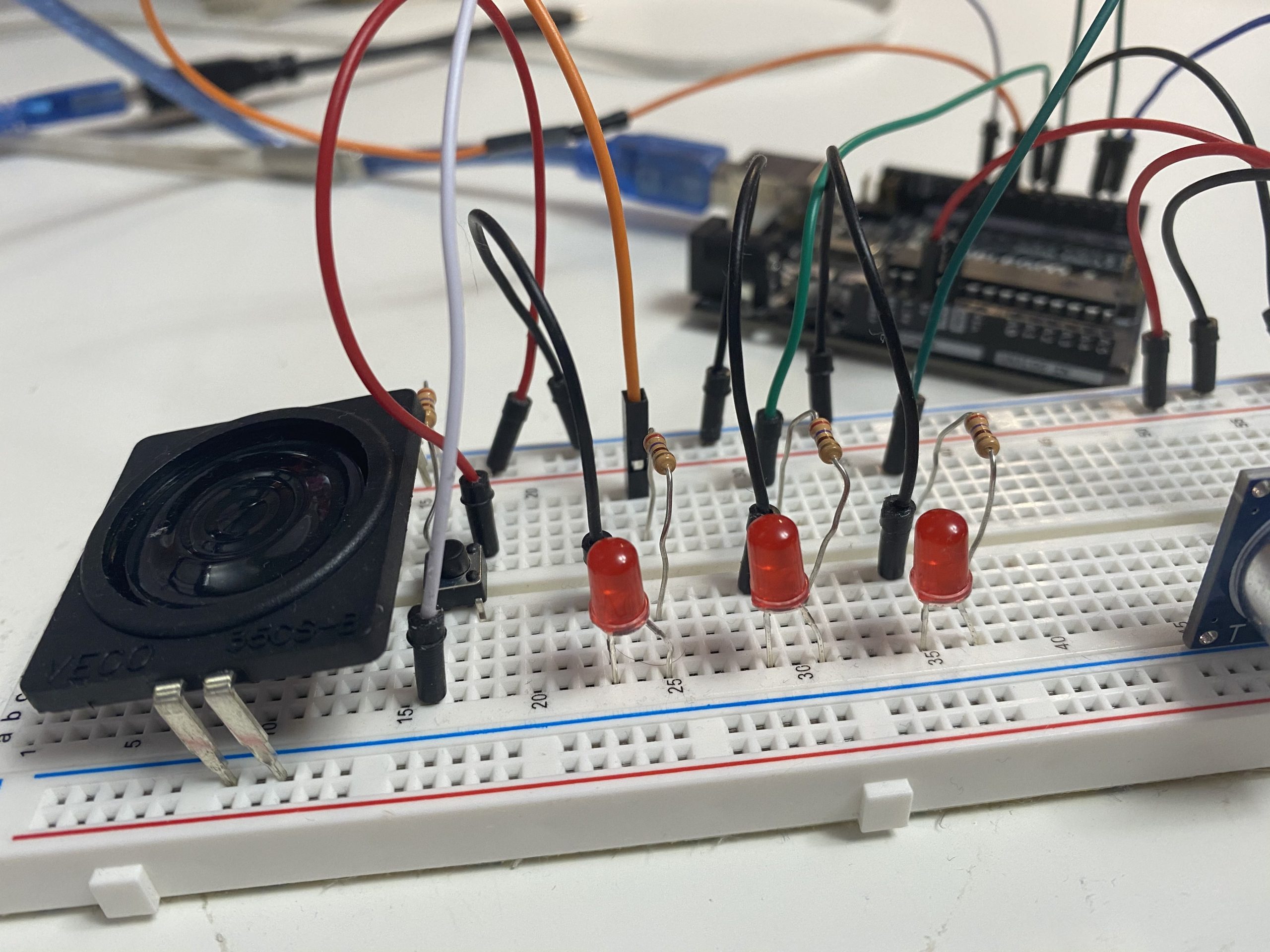
- Prototype
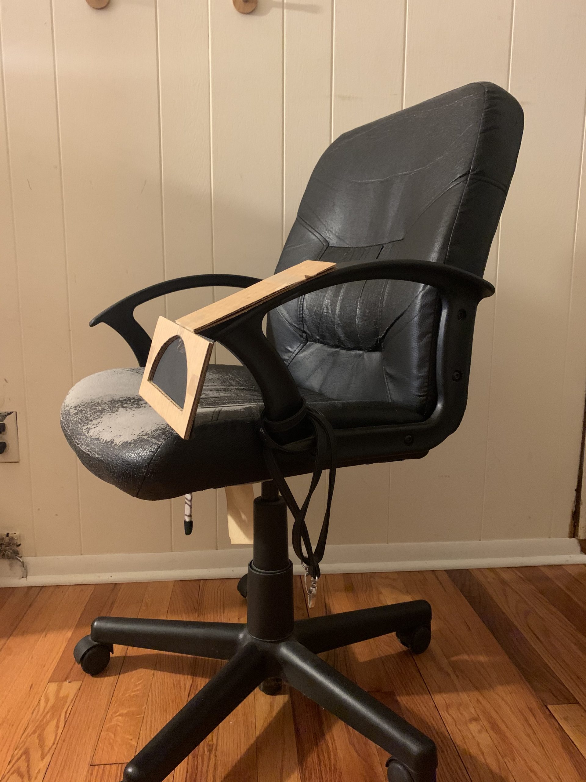
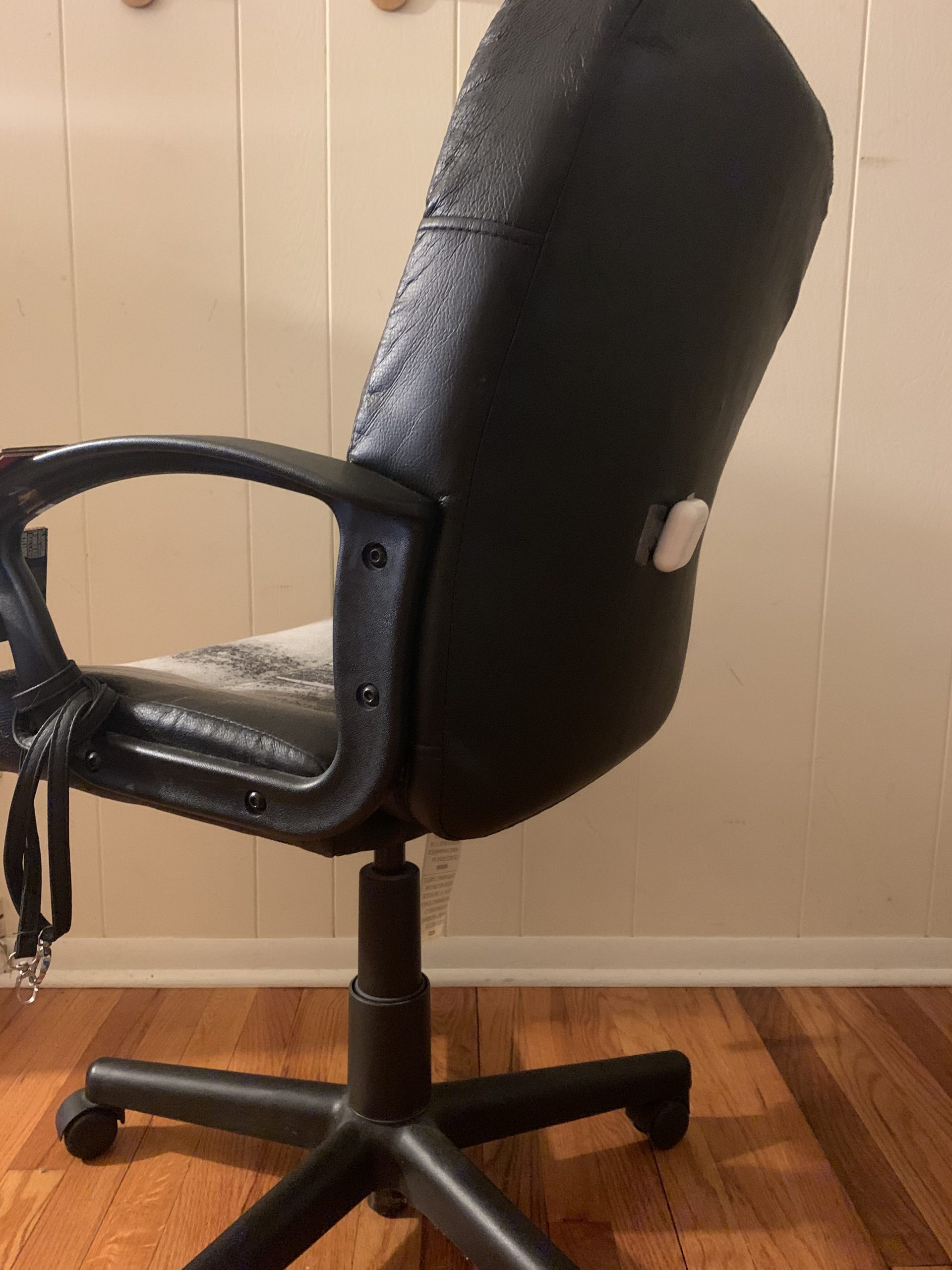
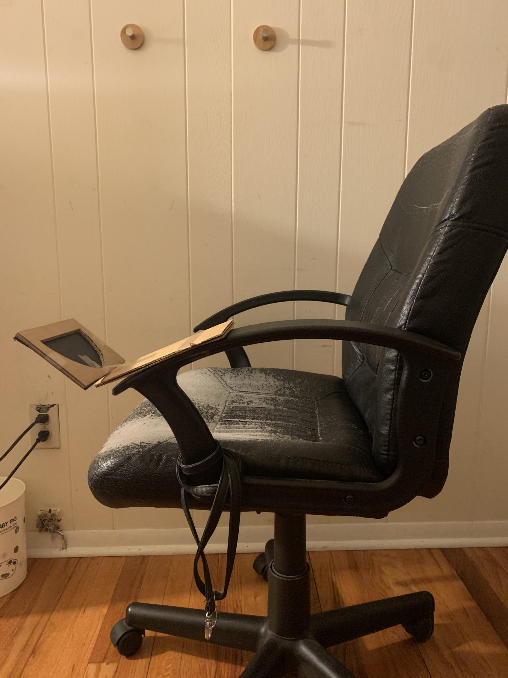
Following the general description of our initial design sketch, we developed a prototype as illustrated below. The ultrasonic sensors would be attached on the back of the wheelchair. The speaker + visualizer module (made of three LED’s with a diffusing material on top of them) would be mounted at the end of the armrest and would communicate with the user about the proximity of the objects. The visualizer would be in a shape of a semicircle, divided into three with each third representing each ultrasonic sensor. Each of them would have three states: white (no objects close by) dim red (pink) (objects are kind of close by) and red (objects are very close). The speaker would have a corresponding output. No sound (no objects close by) slow beeping (objects are kind of close by) and high-pitched, fast beeping (objects are very close).
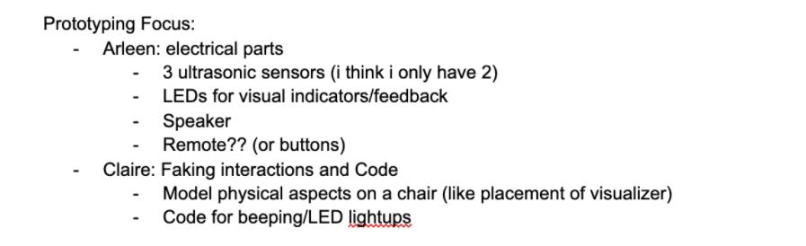
Division of Work for Prototype
Close-up of the single ultrasonic sensor I had modeling the part of the device meant to have the arrangement of 3 ultrasonic sensors.
Close-up of the LED arrangements and speaker placed there modelling the alert/visualization system for the user depending on the ultrasonic sensor feedback.
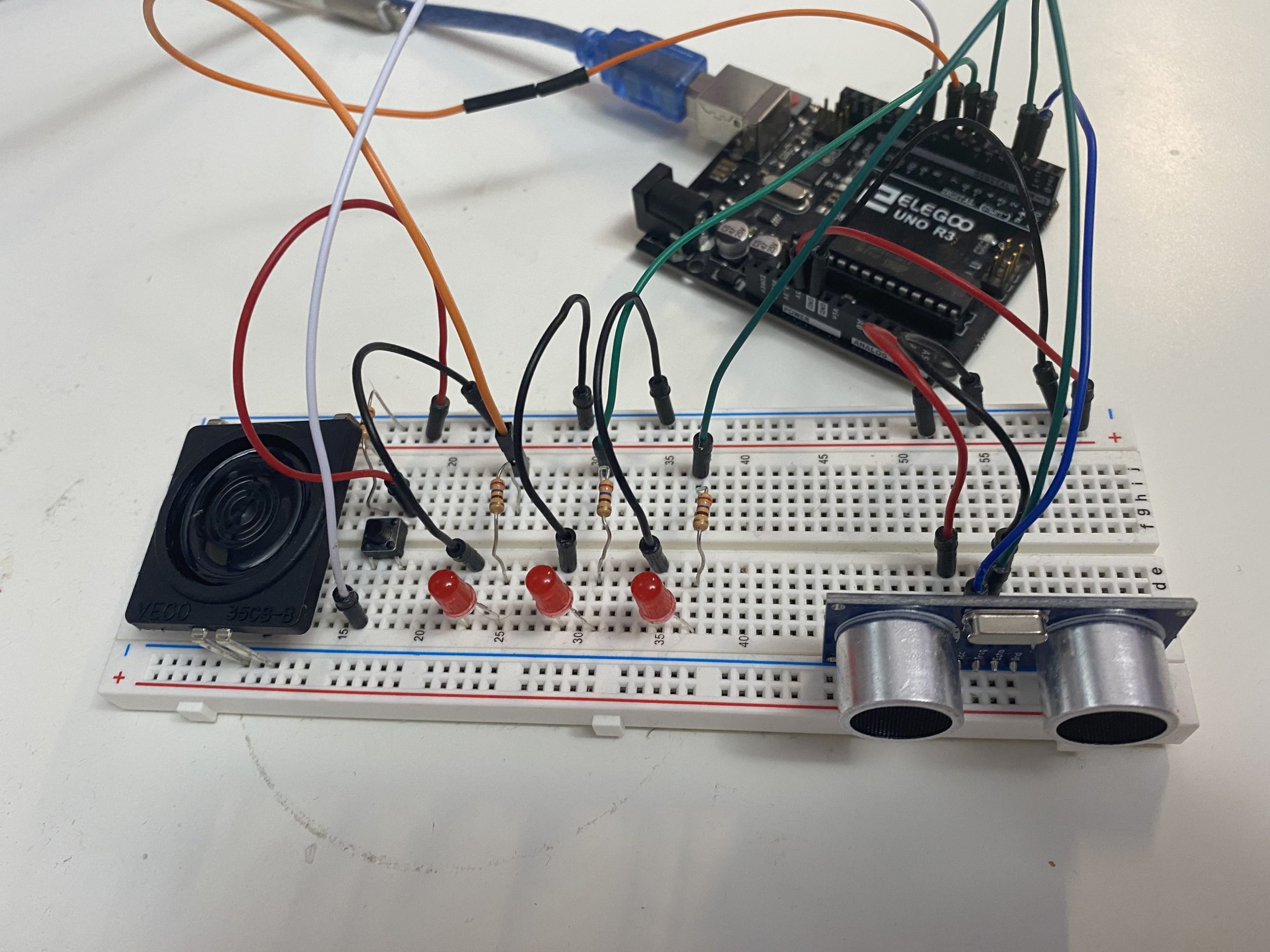
Overall scale of my prototype with all the essential electrical components mounted together.

Visualizer display
Visualizer (deactivated)
Placement of the sensor
Visualizer (activated)
After presenting our prototype and receiving feedback, we outlined the general direction that we want to head for the next step in the project. We received more photos from Brenda that show blindspots for her wheelchair that we could address using our new device. Following are the changes we decided to implement on our design moving forward.
- Change to vibration instead of auditory beeping feedback
- Lower detection range of ultrasonic sensors to detect pets & fallen objects
- Keep version with ultrasonic sensors all active, visualizer will show which direction detects closest thing corresponding to light intensity
- Keep awareness about armrest prone to easy damage, add to inside of pocket attached to armrest instead
- Will get image of armrest area and blind spot on back of chair
- Dogs might be able to hear the ultrasonic ping and not like it – find a higher-frequency ultrasonic device.
- Research
The Research part and the Design Development were done simultaneously, following the Gantt Chart that we made after finishing the prototype presentation.
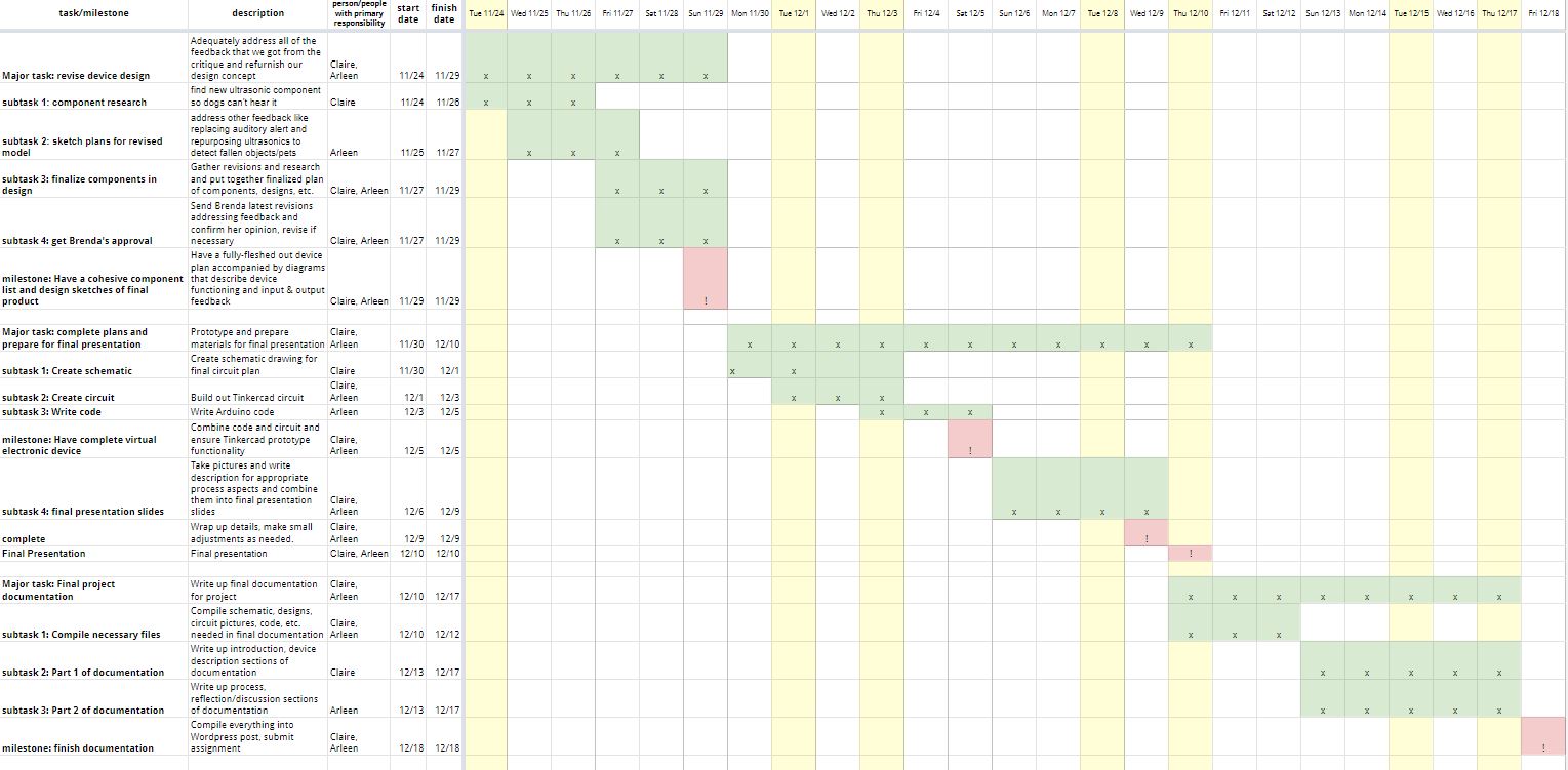
Gantt Chart
The research was primarily for finding a component that could replace the 40kHz-ultrasonic sensor since the dogs might be able to hear up to 60kHz-ultrasound be irritated by it. We were able to find a good alternative to the ultrasonic sensors for this project – the IR sensors! They use Infrared waves to measure the proximity to the objects. However the IR sensors have a much smaller cone of range than the ultrasonic sensors, as illustrated in the diagram below.
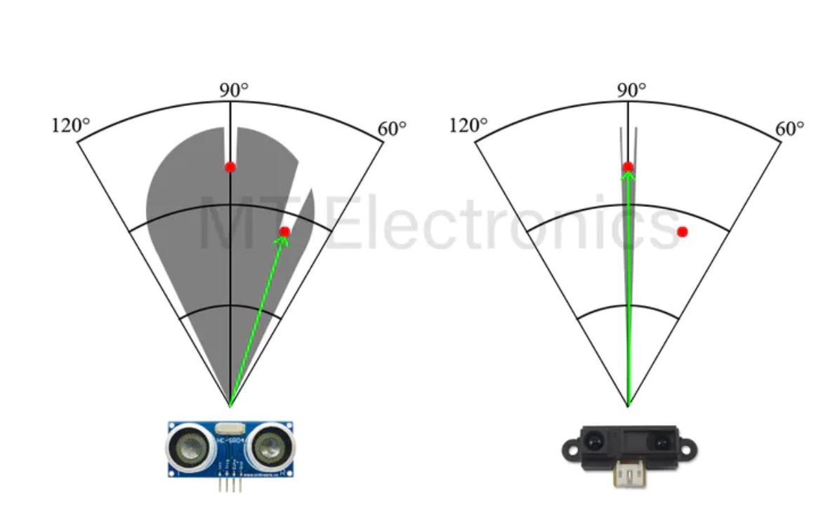
Range for US Sensor vs IR Sensor
(The full document for alternative sensor could be found here)
However, we figured that the smaller cone of range could be compensated by putting several ones of them in a row.
- Design Development.
In the Design Development part, we made changes to the design appropriate for our new concept – a detecting system that would sense pets or fallen objects that may get stuck in the space below her wheelchair or would be extremely difficult for Brenda to see.
Instead of placing the sensors in the middle of the back of her wheelchair, we decided to place them lower. Following the feedback that the speaker would irritate both the user and the animal friends, we decided to use a pancake vibrator instead of the speaker. We decided to leave the 3-LED module in to have a bigger range of communication capabilities. But instead of each one representing each sensor, we changed the interaction so that each LED would represent the level of proximity. At the end, we decided to include options for both ultrasonic sensor and infrared sensor as you can see in the renders. Ultrasonic sensor has an advantage that it would be able to scan a wider range – 180 degrees all around without no blind spot, but IR sensor would be able to sense not just a fallen object but a grade change and alert the user of it.
4. Conclusion and Lessons Learned
After the final presentation, we had a wonderful experience receiving insightful and thoughtful feedback from everyone, many of which appraised our idea and process, making us overjoyed for having our strenuous efforts recognized. In two separate comments, our extensive research process was complemented, being called “really thoughtful and well-researched” and “lloved seeing all the considerations”. Concerning the more specific feedback we received about our design process, we received a comment about our auditory vs. sensory feedback system considerations, saying that they “really enjoy the super high pitched sound,” however we think that the writer may have actually slightly misunderstood our presentation and regarded the speaker as our final settled decision when we actually finalized it with the vibration motor. In another aspect, someone commented on our considerations for our sensor research, citing how “it was really interesting to think about the pets’ state,” which definitely made us feel all our efforts were with it.
On the topic of the process, due to the nature of the semester, our project was done entirely through us collaborating remotely, which was definitely an interesting but challenging experience. What worked most effectively for us was definitely our Zoom collaboration sessions where we just stayed on call with each other and finished our specific allocated sections of assignments. While they were very productive, continuously setting up a time to meet up that worked for both of us purely through text was frustrating at times, and in the end, actually caused us to do more of splitting up work and finishing on our own time, which evidently did slow down productivity but still effectively got the work done. Towards the end, we had less and less collaboration sessions due to the busy nature of our other classes, so as a future consideration, we could have put in more effort towards the end to maintain our prime productivity rate.
Not only was the experience of collaborating remotely somewhat new, but it was also our first time working with a disabled person. The most interesting aspect was definitely seeing just how different our lives and mindsets were, since our disabled partner, Brenda, had severely limited functionalities and thus had a completely different experience even with everyday trivial tasks. It was definitely noticeable how her reliance on all these assistive technologies also shaped her mindset of what she considered as problems that we would never have thought of from our perspective, giving us a lot of insight into what life looks like for people in different circumstances than us. This experience, and that of the final project’s concept as a whole has definitely broadened our horizons and taught us to look at things in a different way while practicing thinking from other viewpoints.
5. Technical Details
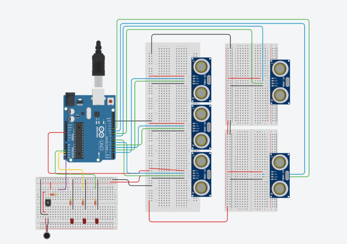
TinkerCAD Screenshot
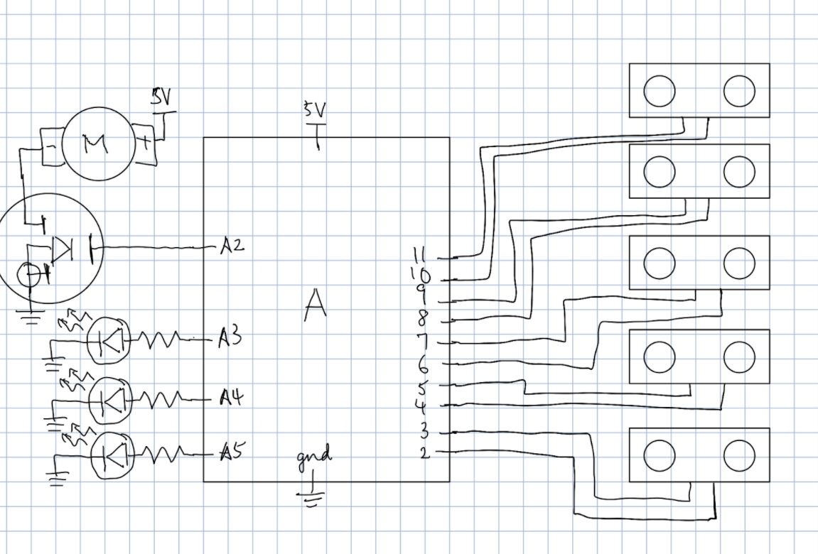
Schematics
Code:
/*
 * Final Project
 * Arleen Liu (arleenl), Claire Koh (juyeonk)
 * 2 hours
 *
 * Collaboration: None
 *
 * Challenge: Figuring out best and most accurate feedback
 * mechanisms from the sensors for the visualizer made of
 * LEDs and the vibration motor for an intuitive understanding.
 *
 * Next Time: Research and experiment even further with
 * different feedback mechanism for ease of the user.
 *
 * Description: An assistive device meant to detect the
 * presence of any obstacles behind a person and provide
 * vibration/visual feedback to the user about the proximity
 * of potential objects blocking the way.
 *
 * Pin mapping:
 *
 * pin |     mode     | description
 * ----|--------------|------------
 * 2    INPUT           Ultrasonic 1 Trig
 * 3    INPUT           Ultrasonic 1 Echo
 * 4    INPUT           Ultrasonic 2 Trig
 * 5    INPUT           Ultrasonic 2 Echo
 * 6    INPUT           Ultrasonic 3 Trig
 * 7    INPUT           Ultrasonic 3 Echo
 * 8    INPUT           Ultrasonic 4 Trig
 * 9    INPUT           Ultrasonic 4 Echo
 * 10   INPUT           Ultrasonic 5 Trig
 * 11   INPUT           Ultrasonic 5 Echo
 * A2	OUTPUT          Red LED 1
 * A3	OUTPUT			Red LED 2
 * A4   OUTPUT          Red LED 3
 * A5   OUTPUT          Vibration Motor
*/


const int MOTOR_PIN = A5;
const int LED1_PIN = A4;
const int LED2_PIN = A3;
const int LED3_PIN = A2;

const int TRIG_PIN1 = 2;
const int ECHO_PIN1 = 3;
const int TRIG_PIN2 = 4;
const int ECHO_PIN2 = 5;
const int TRIG_PIN3 = 6;
const int ECHO_PIN3 = 7;
const int TRIG_PIN4 = 8;
const int ECHO_PIN4 = 9;
const int TRIG_PIN5 = 10;
const int ECHO_PIN5 = 11;

const int SONAR_NUM = 5;      // Number of sensors.

int TRIG_PINS[SONAR_NUM] = {
  TRIG_PIN1,
  TRIG_PIN2,
  TRIG_PIN3,
  TRIG_PIN4,
  TRIG_PIN5
};

int ECHO_PINS[SONAR_NUM] = {
  ECHO_PIN1,
  ECHO_PIN2,
  ECHO_PIN3,
  ECHO_PIN4,
  ECHO_PIN5
};

void setup() {
  Serial.begin(115200); // Open serial monitor at 115200 baud to see ping results.
  pinMode(MOTOR_PIN, OUTPUT);
  pinMode(LED1_PIN, OUTPUT);
  pinMode(LED2_PIN, OUTPUT);
  pinMode(LED3_PIN, OUTPUT);

  pinMode(TRIG_PIN1, OUTPUT);
  pinMode(ECHO_PIN1, INPUT);
  pinMode(TRIG_PIN2, OUTPUT);
  pinMode(ECHO_PIN2, INPUT);
  pinMode(TRIG_PIN3, OUTPUT);
  pinMode(ECHO_PIN3, INPUT);
  pinMode(TRIG_PIN4, OUTPUT);
  pinMode(ECHO_PIN4, INPUT);
  pinMode(TRIG_PIN5, OUTPUT);
  pinMode(ECHO_PIN5, INPUT);
}

long currentmillis;

void loop() {
  float minDist = 100000000.0;
  for (uint8_t i = 0; i < SONAR_NUM; i++) {

    // Clears the trigPin
     digitalWrite(TRIG_PINS[i], LOW);
     delayMicroseconds(2);
     // Sets the trigPin on HIGH state for 10 micro seconds
     digitalWrite(TRIG_PINS[i], HIGH);
     delayMicroseconds(10);
     digitalWrite(TRIG_PINS[i], LOW);
     // Reads the echoPin, returns the sound wave travel time in microseconds
     float duration = pulseIn(ECHO_PINS[i], HIGH);
     // Calculating the distance
     float distance = duration*0.034/2;
    //Serial.println(distance);
    if (distance < minDist) {
      minDist = distance;
    }
  }
  Serial.println(minDist);
  if (minDist >= 80) {
      digitalWrite(LED1_PIN, LOW);
      digitalWrite(LED2_PIN, LOW);
  	  digitalWrite(LED3_PIN, LOW);
      Serial.println("No LED's");
  	}
  if (minDist <= 80 && minDist > 60) {
    analogWrite(MOTOR_PIN, 255);
    digitalWrite(LED1_PIN, HIGH);
    Serial.println("1 LED lit up");
  }
  if (minDist <= 60 && minDist > 40) {
    analogWrite(MOTOR_PIN, 255 * (3 / 4));
    digitalWrite(LED1_PIN, HIGH);
    digitalWrite(LED2_PIN, HIGH);
    Serial.println("2 LEDs lit up");
  }
  if (minDist <= 40 && minDist >20) {
      analogWrite(MOTOR_PIN, 255 * (1 / 2));
      digitalWrite(LED1_PIN, HIGH);
      digitalWrite(LED2_PIN, HIGH);
      digitalWrite(LED3_PIN, HIGH);
      Serial.println("3 LEDs lit up");
    }
  if (minDist <= 20) {
    Serial.println("LEDs blinking");
    if (millis()- currentmillis >500) {
      	digitalWrite(LED1_PIN, LOW);
      	digitalWrite(LED2_PIN, LOW);
      	digitalWrite(LED3_PIN, LOW);
      	currentmillis = millis();
    } else {
      	digitalWrite(LED1_PIN, HIGH);
      	digitalWrite(LED2_PIN, HIGH);
      	digitalWrite(LED3_PIN, HIGH);
      }
  	}

  delay(10);
  //Serial.println();
}
Design File (DXF) Download here