This assistive device uses spine position detection and tension sensing to detect slouching in order to remind you and ensure your torso is always held in a correct and healthy posture.
Final Product
The above video shows the posture corrector in action, where my hand movements simulate a person slouching, and the faint vibrating noise being the alert for the wearer to correct their posture.
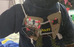
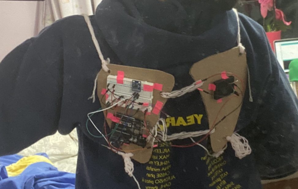
Posture Corrector in action being worn on my back
Clearer picture of the overall finished product
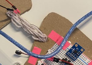
Closeup of the accelerometer used for position detection, the conductive thread interweaved with the middle strap for tension detection, and the pancake motor for a vibration alert
Process
A lot of thought went into how exactly to detect slouching for my assistive device. I ended up with trying two different measures, separated into version 1 (V1) and version 2 (V2) based on their complexity of implementation. V1 was a simple accelerometer to detect the angle of my spine, and V2 involved somehow using tension to detect when my shoulders were slumped forward. The idea that developed was that having either method of measurement would be acceptable for the device, but having both would be nice.
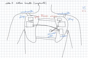
Beginning stages of my ideation for the posture corrector – a sketch
In my ideation sketch, I purposely left the tension sensor area of the sketch vague and blank because I was unsure how to approach this, as it was the most complex part of my assistive device. After looking into load cells and other related sensors, I was directed to a homemade version using conductive thread that changed resistance depending on how stretched out it was. This significantly increased the complexity of the sensor, which later affected the effectiveness of my final outcome.
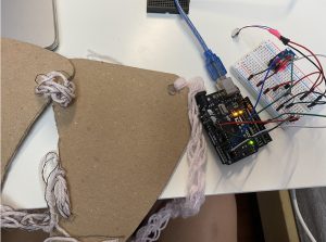
The initial stages of building – the general shape structure is there and I began wiring/testing code for the electronics to mount
Wiring up all the other parts and completing V1 was very straightforward, however when actually implementing the tension sensor as a V2 feature, several complication and design decisions changed as a result. I was going to use an elastic band originally to connect the two platform pieces, but the need for the conductive thread to be interwoven in convoluted loops resulted in me using finger knitting as the final process to create all the straps to accommodate the homemade sensor design.
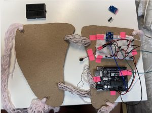
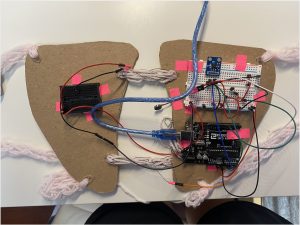
A shot of the device almost completely assembled and mounted – only the tension thread was left to wire up completely
Discussion
Upon reflect on my overall project and the process through which I arrived at the final end result, I was definitely challenged in various aspects along the way. From the initial ideation stage to actually building the device on my own, given the amount of creativity and freedom we were given with the project, I realized the actual difficulty in translating an idea into a solid implementation plan and actually building it according to the plan.
While I am proud of the fact that I was able to build almost everything according to the original idea after I finalized my sketch, especially in terms of functionality, I was very dissatisfied with my general ability to build something sleek and elegant. My end product functioned properly and matched my sketch in terms of the components, with the only shortcoming being the complex tension sensor working unreliably at times, but I feel the general aesthetic was clunky and looked like it was an inconvenience. Coding and wiring came easily to me, but this made it apparent that a significant limitation of mine was designing.
In fact, the comments I received as critique both concerned the aesthetics of the product. Someone suggested that “this could be awesome integrated into a jacket or some type of clothing for more discrete wearing,” which I recognized as a potential solution to help improve the appearance of the product and make it more pleasing to view. Another person asked me “Any ideas for organizing the wires in your project? Is there any danger of getting disconnected while you are moving around?,” which prompted me to think about the fact that wiring placement was definitely a detail I would pay more attention to in the future for general design considerations for the user.
Other than these specific suggestions, looking back, I definitely would have spent more time in the planning stage on all the miniscule details concerning design decisions specifically, and put more effort and importance into the prototype, especially for the base structure that would hold everything together.
Technical Information
Schematic:
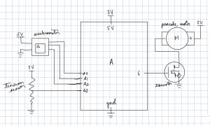
Schematic diagram for posture corrector
Code:
/*
 * Project 2: Assistive Technology
 * Arleen Liu
 *
 * Collaboration: Plusea, for the tension sensor idea using
 * conductive yarn.
 *
 * Challenge: Figuring out how to implement the tension sensor in
 * a stable and consistent manner to maximize its effectiveness
 *
 * Next Time: For projects with many components, test each
 * individual part more thoroughly to make the assembly portion
 * of the building process more smooth.
 *
 * Description: An accelerometer detects the angle of the spine
 * and a tension sensor built from conductive thread uses the
 * difference in resistance to detect shoulder slumping, and if
 * either measurement goes beyond a certain tuned threshold, the
 * pancake motor vibrates to give an alert.
 *
 * Pin mapping:
 *
 * pin | mode | description
 * ----|------|------------
 * 6    OUTPUT pancake motor
 * A0   INPUT  accelerometer
 * A1   INPUT  accelerometer
 * A2   INPUT  accelerometer
 * A3   INPUT  tension sensor
*/

const int X_PIN = A2;
const int Y_PIN = A1;
const int Z_PIN = A0;
const int YARN_PIN = A3;
const int MOTOR_PIN = 6;

// Volts per G-Force
const float sensitivity = 0.206;
const float threshold = -3.92;
const int threshold2 = 700;

void setup() {
  //Initializing pins
  pinMode(MOTOR_PIN, OUTPUT);
  //analogReference(EXTERNAL);
  pinMode(X_PIN, INPUT);
  pinMode(Y_PIN, INPUT);
  pinMode(Z_PIN, INPUT);
  pinMode(YARN_PIN, INPUT);

  //Initializing other elements
  Serial.begin(9600);
}

void loop() {

  float x;
  float y;
  float z;

  // Read acceleration pins and handle sensitivity
  x = (analogRead(X_PIN) - 512) * 3.3 / (sensitivity * 1023);
  y = (analogRead(Y_PIN) - 512) * 3.3 / (sensitivity * 1023);
  z = (analogRead(Z_PIN) - 512) * 3.3 / (sensitivity * 1023);
  Serial.print("x: ");
  Serial.print(x);
  Serial.print(", y: ");
  Serial.print(y);
  Serial.print(", z: ");
  Serial.println(z);
  Serial.println(analogRead(YARN_PIN));

  int aDist = sqrt(pow(x, 2) + pow(y, 2) + pow(z, 2));

  if (y > threshold || analogRead(YARN_PIN) > threshold2) {
    digitalWrite(MOTOR_PIN, HIGH);
  } else {
    digitalWrite(MOTOR_PIN, LOW);
  }

  delay(10);
}