Introduction:
Our final project for the class IDEATE: Introduction to Physical Computing, is a Remote Water Adjustment Variable Enabler (RWAVE). We made this assertive technology for Brenda Dare. We interview Brenda over zoom about her life and asked about what things we could make for her and what daily tasks does she have a lot of difficulty doing. After the interview our team decided that we could make an assistive device that would help Brenda turn on the faucet in her shower without another person helping her.
See here for information about our initial interview with Brenda: https://courses.ideate.cmu.edu/60-223/f2020/work/brenda-seal-team-one/
See here for information about our prototypes: https://courses.ideate.cmu.edu/60-223/f2020/work/brenda-seal-team-1-prototype-documentation/
What We Built:
Our project allows a user to turn the faucets in their shower without having to physically turn them. A user can turn the faucet then using a remote control that controls the faucet knobs like how a tv remote controls a tv. Our projects has motors that controls the temperature and pressure knobs in Brenda’s shower and that is able to receive information from a remote. The remote is able to send information to the faucet controller based on the buttons the user presses. For example if a user presses the button to increase the temperature of the shower water on the remote the motor attached to the temperature knob will move to reflect that and the temperature of the water will increase. The purpose of this device was to allow Brenda to change the temperature and the pressure of her bath water independently. Without this assistive technology Brenda would not be able to bath independently.
Final Appearance:
The way the electronic would look for the remote control
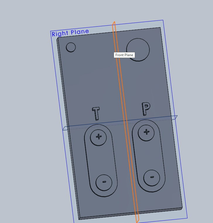
Shows the final design of the remote controller in Solidworks from the front
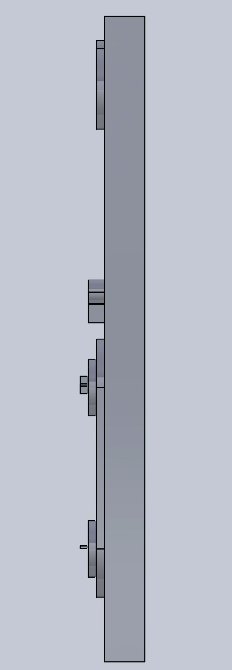
Shows the remote controller from a side view in SolidWorks
This video shows how the remote would control the motors to change the temperature and pressure of the bathtub.
TinkerCad Interaction:
Play the following video at full volume to hear about what is happening. Furthermore the output of this simulated remote is different color light on a neopixel strip. This is the simulated output because on TinkerCad is was impossible to send an output signal using an IR light as would be done if this remote was to be actually made.
Physical Mockup:
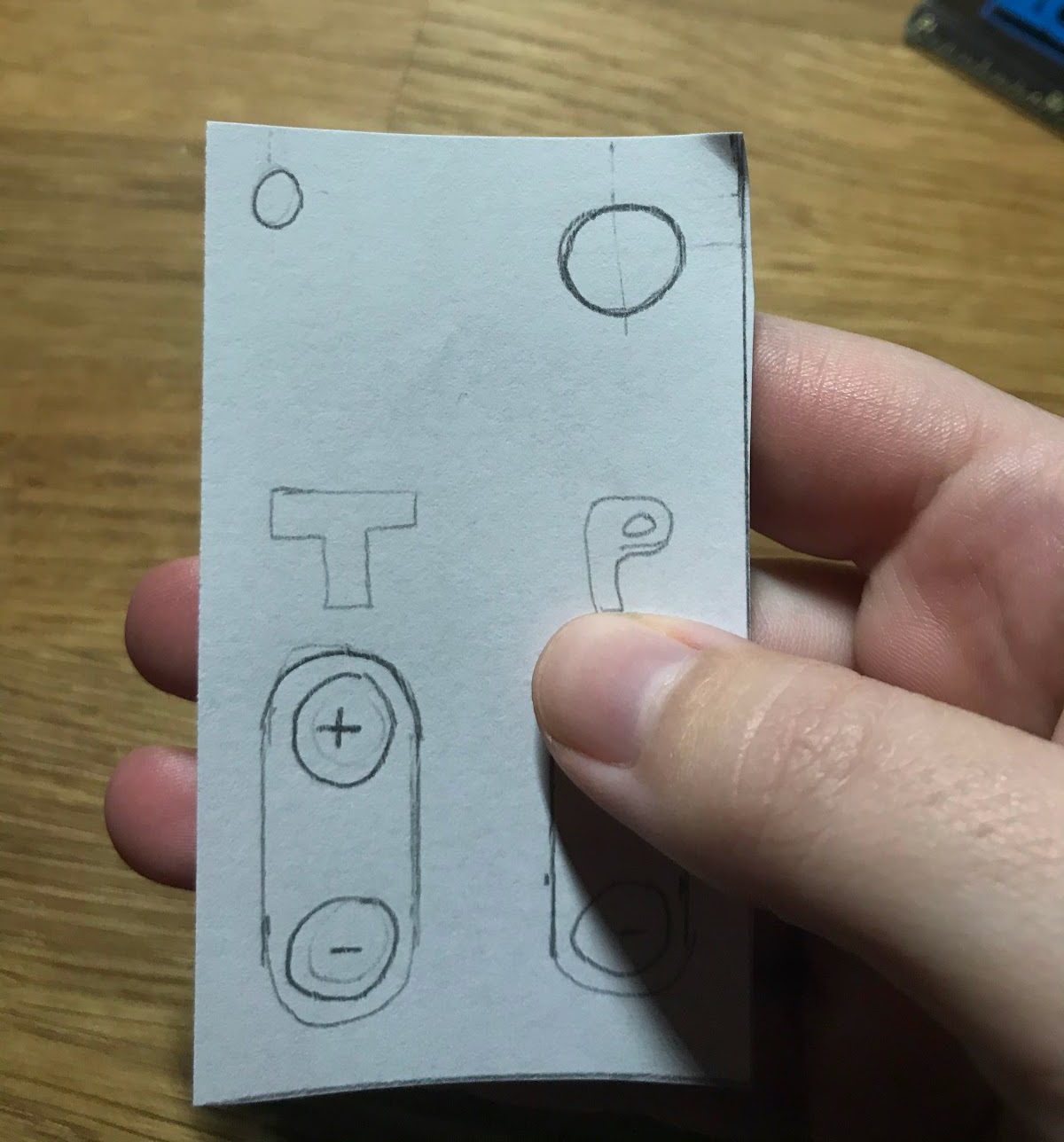
Demonstrates how the remote, that was resized after the prototype, would fit in someone’s hand
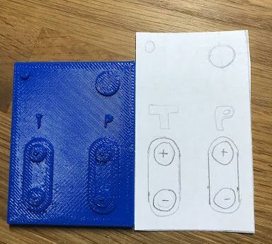
Demonstrates some of the changes made from the prototype of the remote on the left to the final version on the right
Shows how a user would turn on the remote
Demonstrates what the remote would look like when it is turned on
In addition to the remote models, there was also a proof of concept physical model that was made:
This is the physical prototype proof of concept.
This was the only physical element that was created for the motor because the rest of the semester was dedicated predominantly to electronic software design and development of the other parts of the project.
Narrative Sketch:
After a long day at work, dealing with many clients, Brenda decides that she wants to come home to take a bath. Due to Brenda’s condition, she requires assistance from a machine to make her way into the bathtub. After being situated on the opposite end of the bathtub from the faucets, she grabs a remote hanging from a string suction-cupped to the wall and presses the power button. A red LED turns green, and a small screen turns on denoting the pressure and temperature both set to zero. She pushes the temperature buttons to set the temperature to a steamy 90*F. After the perfect temperature, determined by angle and prior testing for now, she starts to press the pressure button, turning the water all the way up to 100 to fill up for a while. Simply turning down the pressure back to 0, then pressing the power button to turn off the system.
How We Got Here:
So, as a refresher, this first picture shows the first ideation for the remote control that we would be manufacturing to fit our needs. This ideation is meant to function more as the “feels like” aspect in order to make the device in the shape that would be easiest to use for someone who might not have the same motor capabilities as someone who does not have Cerebral Palsy. This is the base of where we started. These sketches help influence the first prototype that was 3D printed for the actual touching and holding.
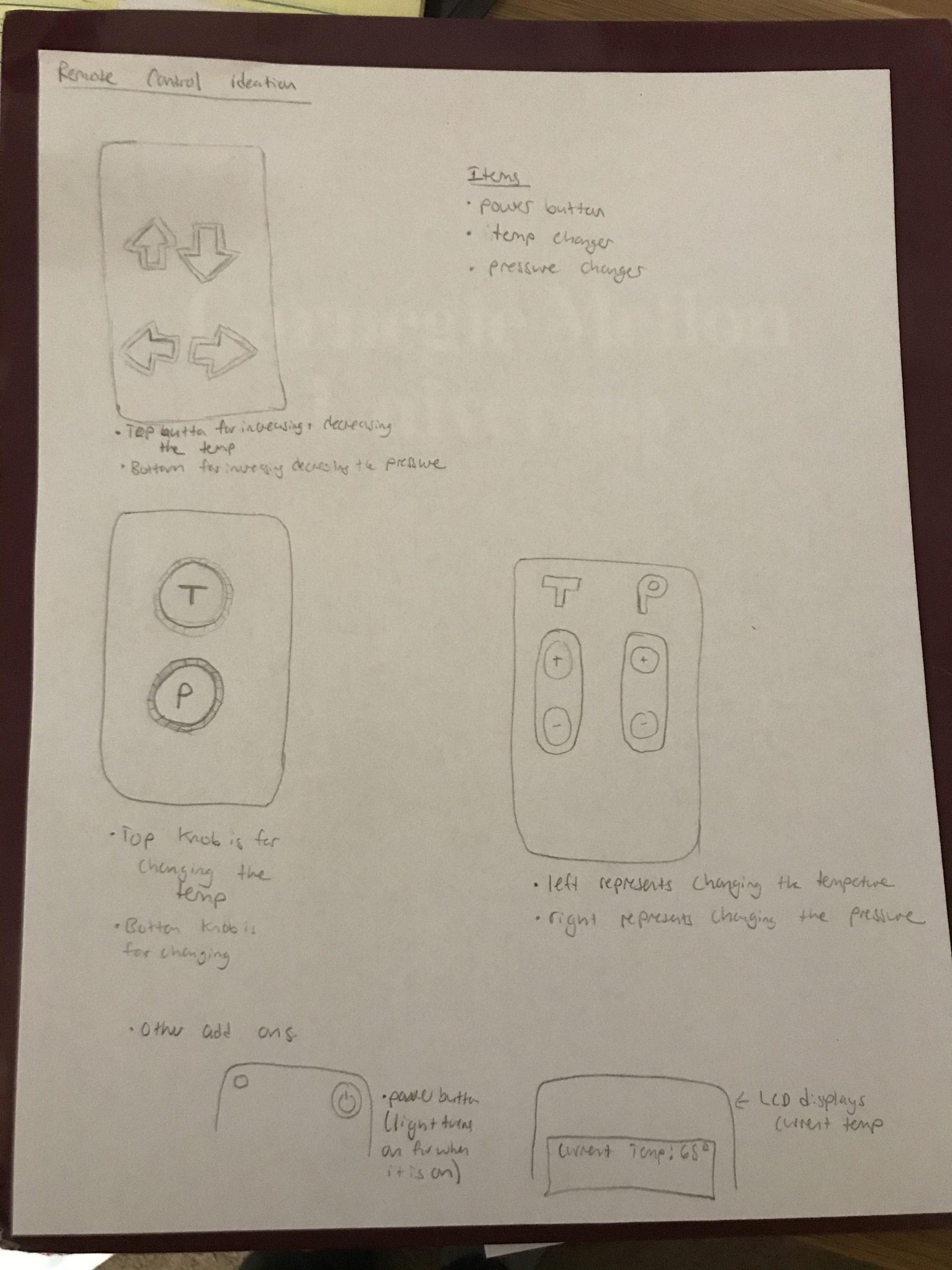
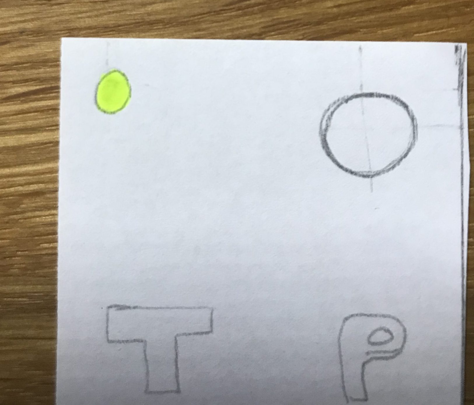
Sketches of possible layouts for the remote
This prototype had a lot of great features: clear buttons and easily identifiable sections because of the letters. Because we are trying to make this device as something that could potentially be marketed, one of the thoughts and considerations made post designing and building the second device would have been adding braille to the remote’s cover. It would not be difficult to 3D print, however, this would have been post-Thanksgiving hiatus from in person for those who decided to return home.
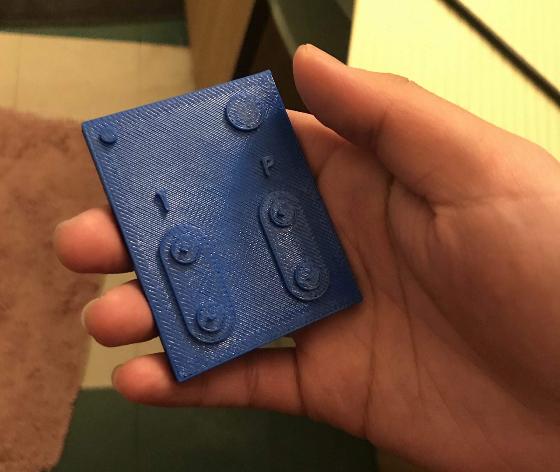
Mimi’s roommate holding the 3D printed remote while giving feedback about its design. Demonstrates how the remote fits in someones hand
After all of the revisions, the remote was a little bit longer and a little bit skinnier in order to accommodate people who have shorter thumbs and are unable to reach all the way across the remote in order to press a button. In hindsight, there were a couple of changes that could have also been made. It could have taken a more ergonomic fit to the hand, enabling the easiest means of pressing the buttons. There could have also been buttons on the backside of the remote to make it more space efficient. A lot of these things could have been added onto if only we had put more thought into how Brenda, or any other person, might end up using the device. It should be mentioned that these could have been accomplished much easier if we were able to be in person and having Brenda “use” the remote, but alas, here we are. 3D printing would definitely be the way to go in order to make small sets for a small number of individuals; however, if this were going to hit the markets, there would probably be better manufacturing methods to produce these cheaper.
The following was derived as a means of creating a circuit that could be turned into a PCB. When we thought about designing our own remote, we thought it would be best to program it ourselves as well. The IR remote that was provided by the kits was unreliable and difficult to press. The buttons were sometimes difficult to tell if they had been pressed or not, so there would be a change of button choice in order to provide a tactile and auditory feedback for the user, in addition to a visual in order to cover all bases.
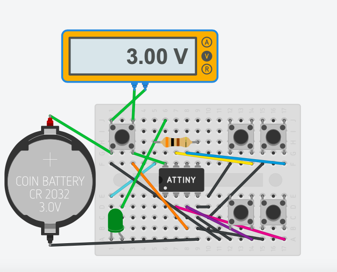
Testing voltages on the remote control simulation to figure out where the problem is
The next few images are going to be looking at the housing and the electronics that go into the actual device that the remote is going to control. All of the components were decided by the type of circuit that is shown in the TinkerCAD drawing later in the post.
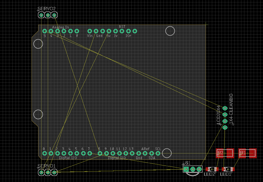
This picture shows the EAGLE CAD sketch that is the start for the PCB that could be placed inside fo the box to allow for continuous use similar to a tv, potentially enabling wireless use.
This is the sketch that outlines all of the parts that go onto EAGLE to generate the PCB.
The following are the designs that were iterated through. Each one changes slightly from the last. At this stage in the project, the design was not fully fleshed out for manufacturing. The hypothetical trumped the need to physically build due to the nature of the presentation. Should there be more time, or we were able to go back and do this over, it would have made more sense to try and make the physical in order to help influence the later iterations of the designs. There could also be more consideration for material and piece design in order to manufacture on a large scale should this be intending to be commercialized.
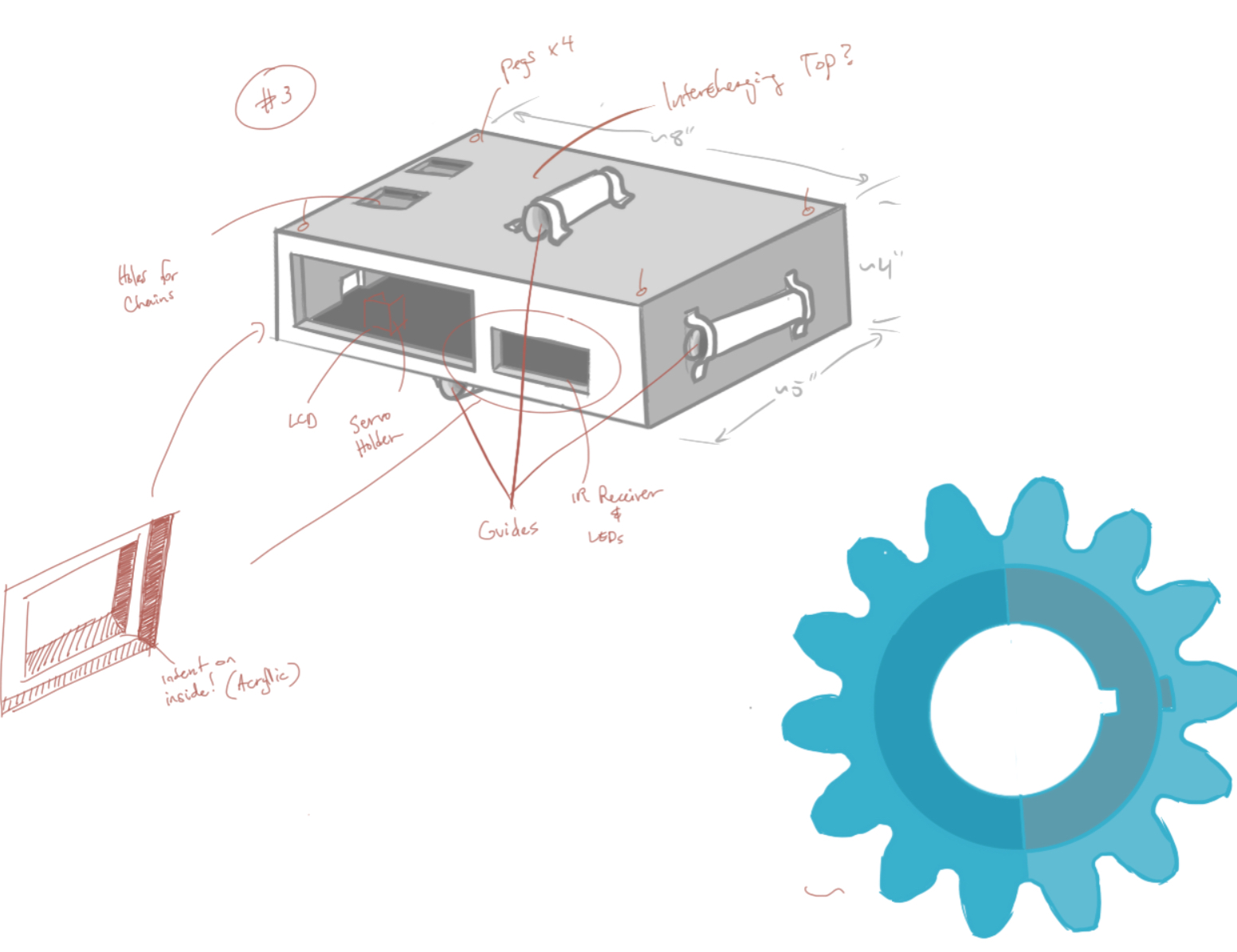
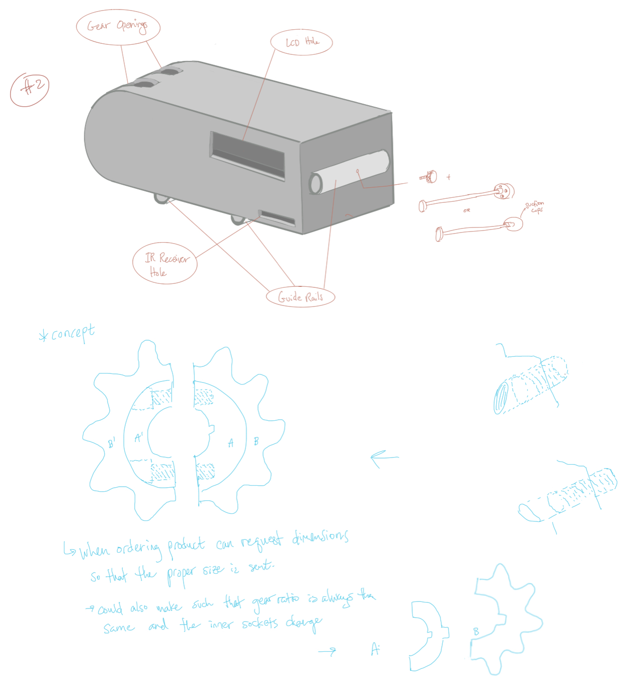
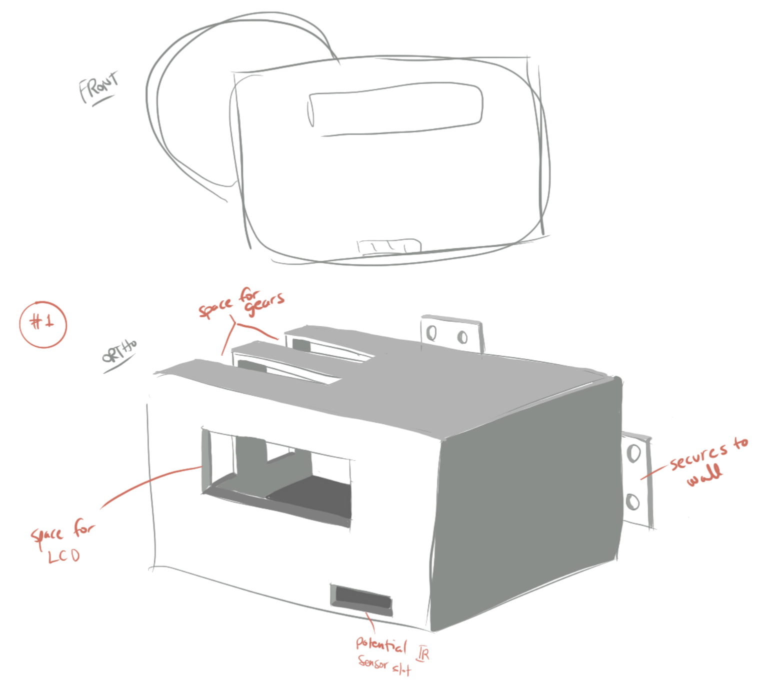
These are the box designs that changed to optimize the space that was being used. It was rather difficult because it was all hypothetical and there was not a physical.
Overall, the plan was followed pretty closely. If anything, the hardest part was communicating with each other about potential ideas and design stuff. Either we were both busy or the platforms created difficult means of communicating effectively. It was also busy with preparing for the final push for finals, so some of the tasks might have been shortened in order to compensate the time. There is more research that can be done for this project, but it is very sastisfactory for the situations and the resources available.
Conclusions:
After the final product presentation we got a lot of positive and constructive feedback from many people. One piece of feedback said, “I think the idea is really great and am excited to see how it will turn out when physically built!” This feedback showed us that the idea of our idea was really valuable and our product could be really useful if it were to be physically built. Another piece of positive feedback we received was, “I appreciate you guys kept iterating and iterating to arrive at the best design you thought of. I think this could be such a useful and practical device for so many groups of people.” This piece of feedback also mentions that our idea would be really useful for many different people. They also commented on the fact that through our iterations we were able to improve the parts of the project we were each working on.
Feedback from a different person was, ” I’d be excited to see how this idea would play out as a physical device! I think the way that you explored the different CAD models to have a better, more universal fit to accommodate for a wider variety of baths shows a lot of great consideration.” This piece of feedback comments about how we made our CAD models universal. From this comment and our discussions after the final presentation it seems like it would be very useful if after we made the final product in real life for Brenda we altered our design so that we could have different standard sets for different types of bathrooms. We made some of our design considerations based on Brenda’s shower setup but there are a lot of different types of bathroom faucets. So in the future it would be nice to make our design more universal or have different subsets of our product for different types of bathrooms.
A final piece of feedback we received was “The device captures the issue that was presented. I would’ve liked more emphasis placed on materials because waterproofing is so critical.” This comment raises the issue of waterproofing our product. We thought about this throughout the design process but did not spend a lot on time on it. We both spent most of our time making sure electrically the product worked and the other parts of the design were good. It was also harder to do this aspect with everything being virtual because we were not really building anything physically. In retrospect we could have devoted more time to making sure everything would be waterproof because this is really an essential part of making sure the product works and is safe to use. Furthermore, going forward with this project making sure everything worked in a water environment would be our next concern.
Overall working remotely this semester for this final project was not as hard as anticipated. It was actually easier to find time to meet and work on this project due to lack of other time commitments like extra curricular activities. It was harder to communicate effectively and understand other people over virtual platforms like zoom. It was also harder to work on the project while not being in the same physical space. In the end we kind of had two separate projects that coexisted to form a final project rather than just have one final project. On the other hand this also made the project easier to work on because we could each work on our own part without needing to schedule time with the other person or wait for the other person to finish their part. Lastly, it was overall disappointing that we couldn’t physically make the final project. Making all the plans and simulating the project was the best that could be done because nothing compares to all the learning done when actually making the product.
We found it vey rewarding to work with Brenda and learn about her life. We enjoyed being able to use the skills we have gained in this class to work on a project that would allow Brenda to be more independent. Furthermore from the feedback it seems like this would be a really useful product for make people and would allow them to live more independently. Hopefully in the future we will be able to physically make this product for Brenda and other people who would benefit from it.
Finally, we really enjoyed working on this product. Going forward, as stated above, we would want to make our product more universal so it could be used in bathrooms with many different types of faucets and make more waterproof design considerations. Thank you Professor Zach for all the help on this project and throughout the semester.
Technical Details:
Mimi:
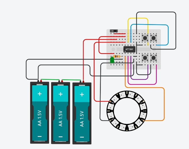
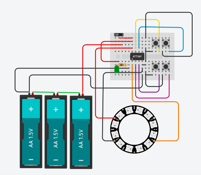
Final electronic setup in TinkerCad
Remote Code:
/*
 * Remote Water Adjustment Variable Enabler (RWAVE)
 * Remote Code
 * Mimi Marino (mmarino)
 *
 * Description: This is the code to control the remote control.
 * There is a button to turn the remote on and buttons that
 * correspond to increasing and descresing the temperature
 * and the pressure respectively. The neopixel strip is there
 * to simulate the signals that the remote would output
 * because you can't use an IR light as I would if I were
 * to make this in real life. Note: it is intentional that if
 * you hold down the button the light stays on.
 *
 * pin   | mode   | description
 * ------|--------|------------
 * 1      input     button PRESSURE_DOWN
 * 2      input     button PRESSURE_UP
 * 3      input     button TEMP_DOWN
 * 4      input     button TEMP_UP
 * 5      output    neopixel ring
 *
 *
 * Credit : Used this tinkercad link to help program the
 * attiny.
 * https://www.tinkercad.com/things/d6fJABMd27t-attiny-pwm
*/

#include <Adafruit_NeoPixel.h>
const int PIXEL_PIN = 5;
const int NUMPIXELS = 12;
Adafruit_NeoPixel pixels = Adafruit_NeoPixel(NUMPIXELS, PIXEL_PIN, NEO_GRB + NEO_KHZ800);

const int TEMP_UP= 4;
const int PRESSURE_UP = 2;
const int TEMP_DOWN= 3;
const int PRESSURE_DOWN = 1;

void setup()
{
  //Sets Neo pixel Strip
  pixels.begin();
  pinMode(PIXEL_PIN, OUTPUT);
  pinMode(TEMP_UP, INPUT_PULLUP);
  pinMode(PRESSURE_UP, INPUT_PULLUP);
  pinMode(TEMP_DOWN, INPUT_PULLUP);
  pinMode(PRESSURE_DOWN, INPUT_PULLUP);

}

void loop()
{
  //checks if TEMP_UP is being pressed
  if (!digitalRead(TEMP_UP)){
    //changes color to RED
    for (int i=0; i < NUMPIXELS; i++) {
        pixels.setPixelColor(i,255,0,0);
        pixels.show();
    }
  }
  //checks if TEMP_DOWN is being pressed
  if (!digitalRead(TEMP_DOWN)){
    //changes color to BLUE
    for (int i=0; i < NUMPIXELS; i++) {
        pixels.setPixelColor(i,0,0,255);
        pixels.show();
    }
  }
  //checks if PRESSURE_UP is being pressed
  if (!digitalRead(PRESSURE_UP)){
    //changes color to PURPLE
    for (int i=0; i < NUMPIXELS; i++) {
        pixels.setPixelColor(i,128,0,128);
        pixels.show();
    }
  }
  //checks if PRESSURE_DOWN is being pressed
  if (!digitalRead(PRESSURE_DOWN)){
    //changes color to GREEN
    for (int i=0; i < NUMPIXELS; i++) {
        pixels.setPixelColor(i,0,255,0);
        pixels.show();
    }
  }
  // if no button is being pressed
  else {
    //delay to make tinkercad work better
    delay (50);
    	//turns off neopixel strip
        for (int i=0; i < NUMPIXELS; i++) {
        pixels.setPixelColor(i,0,0,0);
        pixels.show();
    }
  }

}
Remote Schematic:
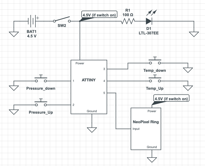
Schematic for the remote
Remote CAD Files:
(Includes STL file, SolidWorks part file and SolidWorks drawing file)
Carl:
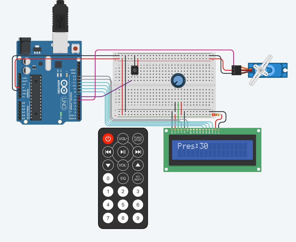
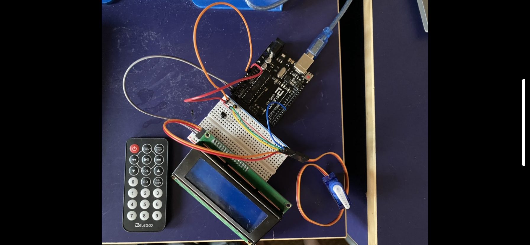
Basic proof-of-concept design for the mechanism meant to show the remote adjusting the motor and changing the LCD.
Motor Code:
// Libraries
#include <LiquidCrystal.h>
#include <IRremote.h>
#include <Servo.h>

// Servo Pins
#define PRESSURE 6

// LCD Pins
#define regsel 13
#define enable 12
#define d7p 11
#define d6p 10
#define d5p 9
#define d4p 8

// IR Pins
#define iroutput 7

// LED Pins
#define offLED 5			// Red
#define onLED 4				// Green

IRrecv irrecv(iroutput);
decode_results results;
LiquidCrystal lcd(regsel,enable,d4p,d5p,d6p,d7p);
//Servo tempServo;
Servo presServo;

// Variables
//unsigned int temp = 0;
unsigned int pres = 0;
bool start = 1;


void setup(){
  Serial.begin(9600);
  irrecv.enableIRIn();
  pinMode(offLED,OUTPUT);
  pinMode(onLED,OUTPUT);
  while (start == 1){
    digitalWrite(offLED,HIGH);
    digitalWrite(onLED,LOW);
    if(irrecv.decode(&results)){
      unsigned int active = results.value;
      if(active == 255){
        start = 0;
        //Serial.println("HERE.");
        break;
      }
    }
  }
  lcd.begin(16,2);
  presServo.attach(PRESSURE);
  //tempServo.attach(5);
}

void loop(){
  digitalWrite(offLED,LOW);
  digitalWrite(onLED,HIGH);
  if(irrecv.decode(&results)){
    //Serial.println(results.value,HEX);
    unsigned int button = results.value;
    //Serial.println(button);
    setVal(button);
    int newPres = map(pres,0,100,0,180);
    presServo.write(newPres);
     displayPres();
    irrecv.resume();
  }
  onOffStatus(start);
}

// Changes the values based on pressed button
void setVal(unsigned int buttonPress){
  switch (buttonPress) {
    case 24735:
      pres++;
      break;
    case 8415:
      pres--;
      break;
    /*case 255:
      start = 1;
      break;*/
  }
}

void displayPres(){
  lcd.setCursor(0,0);
  lcd.print((String)"Pres:"+pres);
}

void onOffStatus(bool temp){
  //Serial.println(temp);
  if(temp != 0{
    lcd.noDisplay();
  } else {
    lcd.display();
  }
}
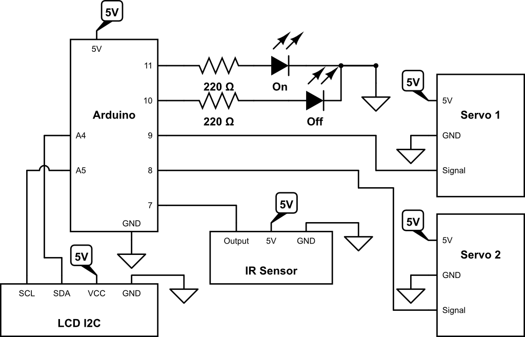
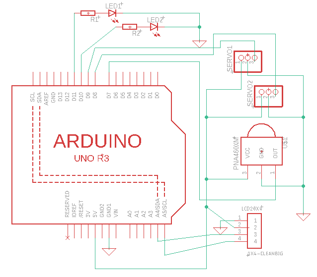
Circuit Lab schematic of the Motor assembly using Servo Motors.