Richard is a graphic and jewelry designer who typically works on drawings for commissions every evening on the couch while he and his wife watch the news. You can see the notes from our initial meeting here.
While he does this, he often has to tilt and position his iPad in different ways to get the right angle to draw from. He typically keeps it on a pillow and props it up with his hand, which doesn’t allow for it to be fully stable, and makes drawing harder. He tries to keep track of the time he’s spent working on each commission in order to keep pricing fair and know for future reference how long similar designs take.
We worked to create a prototype for him to review and give us feedback.
Prototype
Our prototype gave Richard a sense of the scale of the final product, so as to demonstrate both the movement of the board and to understand and look critically at the experience of using the device to assist you in drawing on an iPad. The stand attaches to the back of the board and sits on a table, where it can be moved up and down to better suit Richard’s desired angle of drawing.
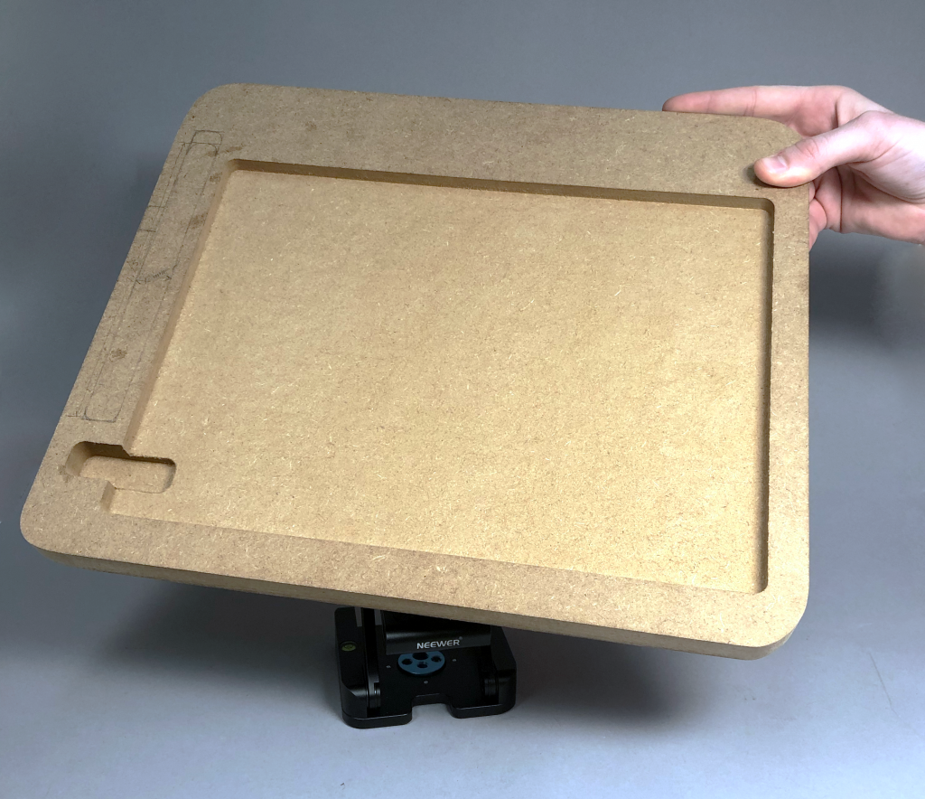
The front of the board holding the iPad was milled to hold Richard’s 12 inch iPad
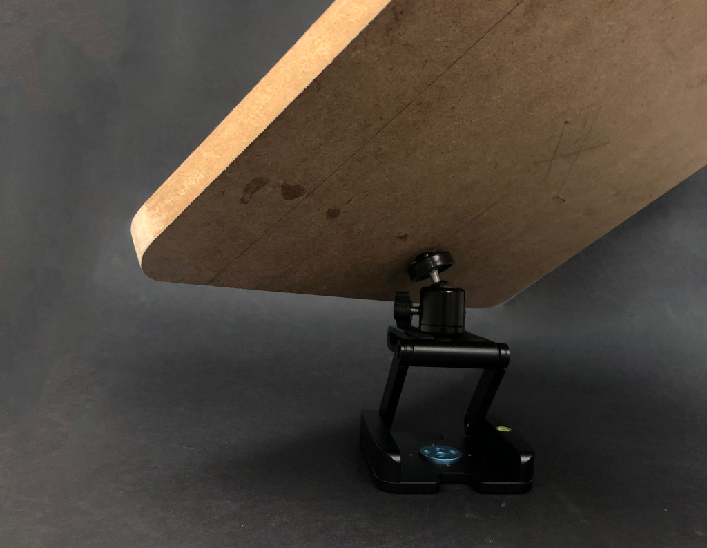
Back view showing the positioning joint attached to the back of the holding board.
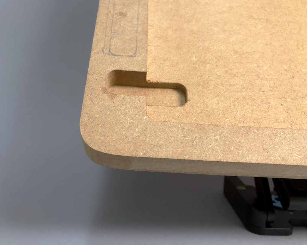
Finger slot to allow Richard to get his iPad back out of its holder.
Process Photos
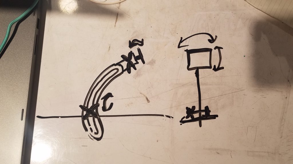
Our initial sketch for the arm mechanism featuring a sliding slot joint for vertical movement and a ball & socket joint for planar rotation.
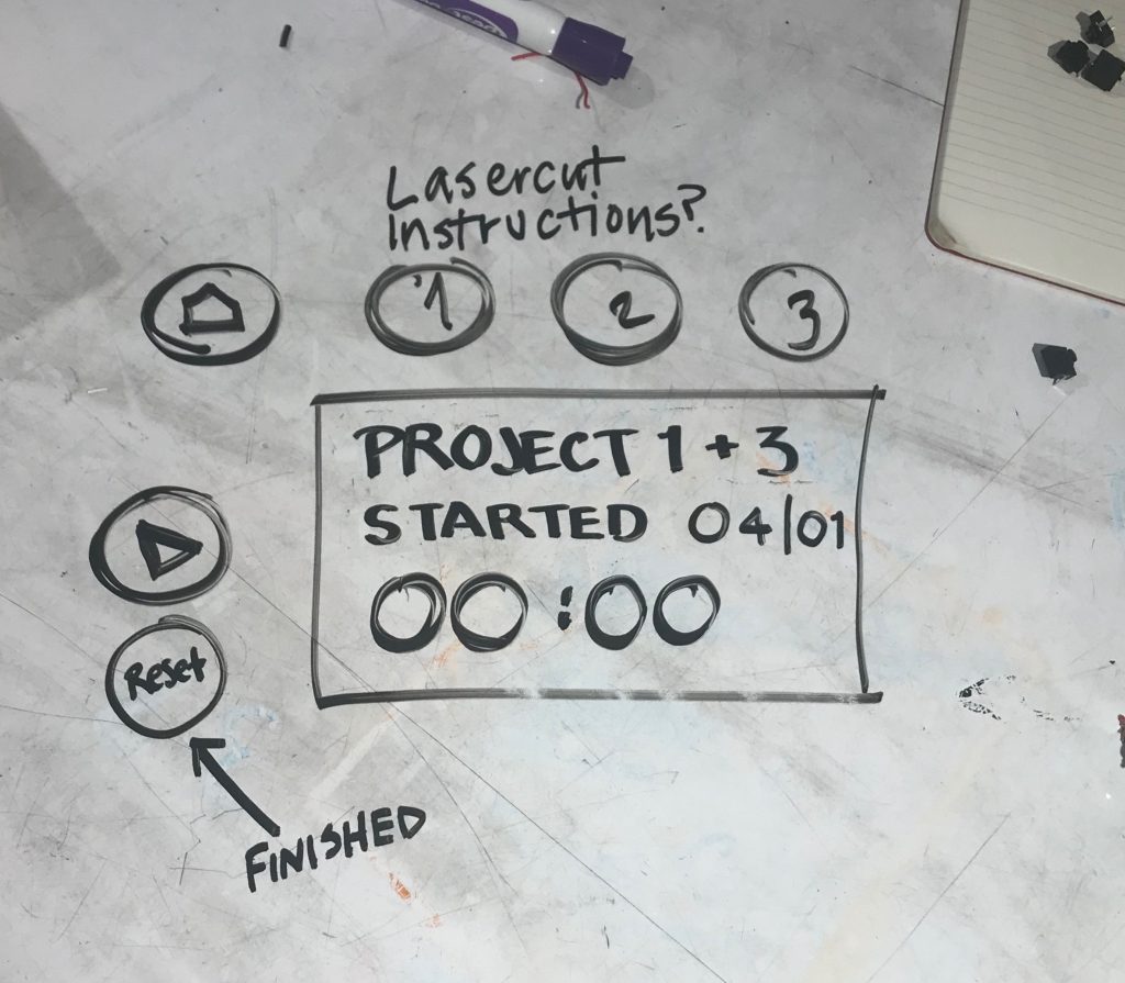
Our initial sketches for the digital interface on the board featuring different buttons for each project, a home button, and start and finish buttons, intended to be built with the LED screens in the Physical Computing room.
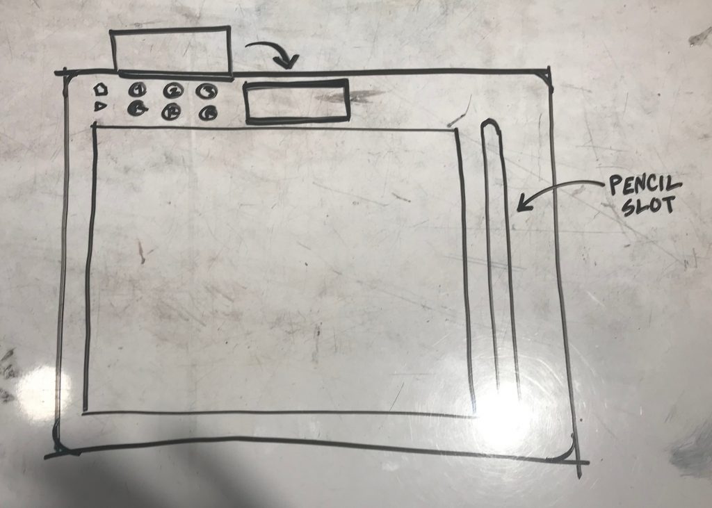
Initial sketch of how all the components would look on the board.
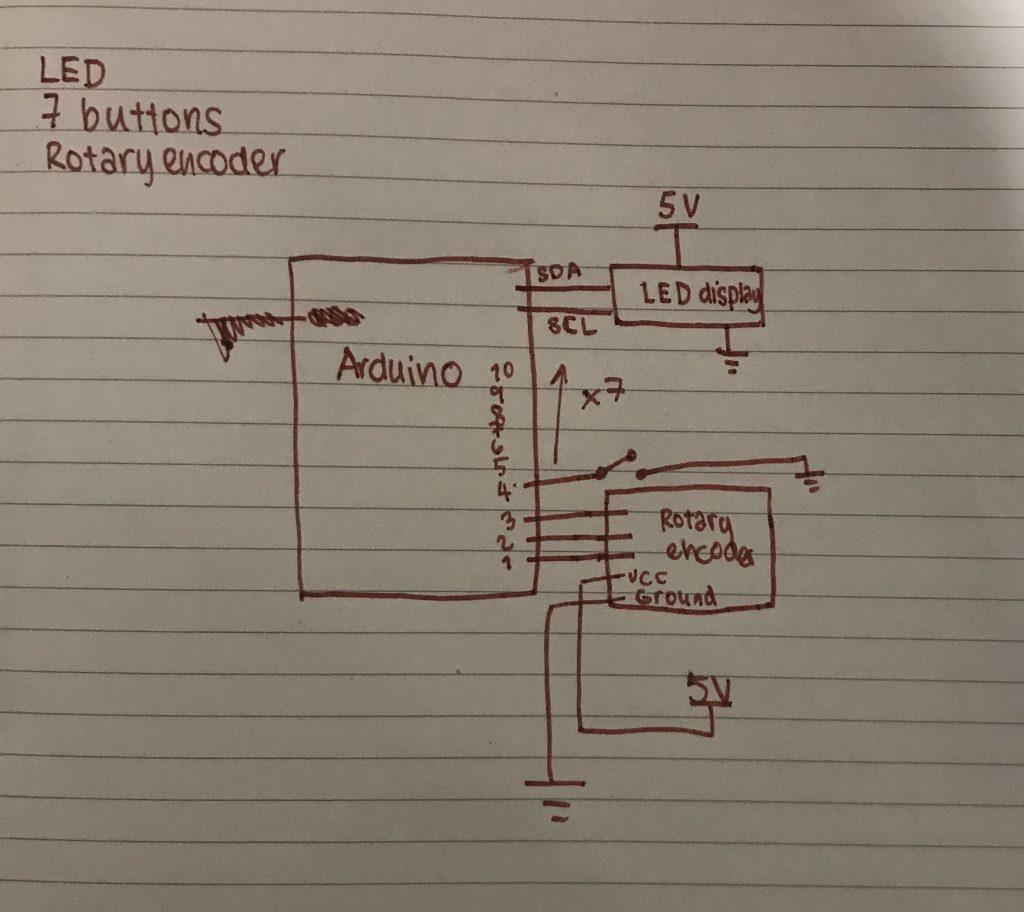
An initial circuit diagram.
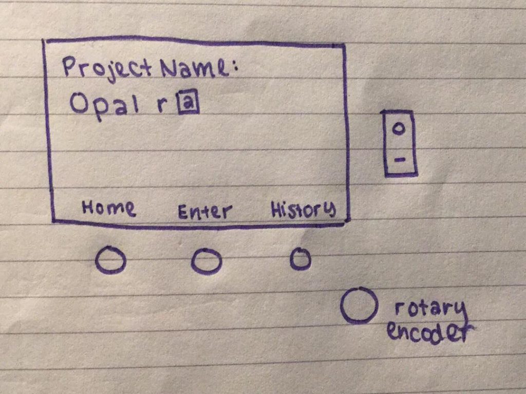
Final concept for electronics interface, coded but with nothing to show as we do not have the display yet, designed around usage of a TFT LED display, which sets a display through individually coded pixels, allowing us to change font sizes and placements to add on-screen variable labels to buttons, cutting down to only three. A rotary encoder allows Richard to enter the name for each project, and an additional power button allows the entire arduino to turn off when not in use, saving battery power.
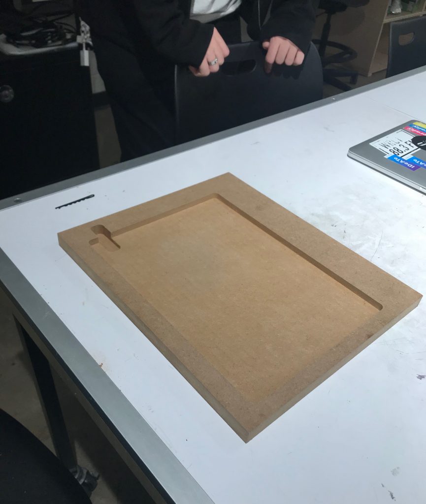
Prototype board with space for iPad milled in along with a finger slot to get it out again.
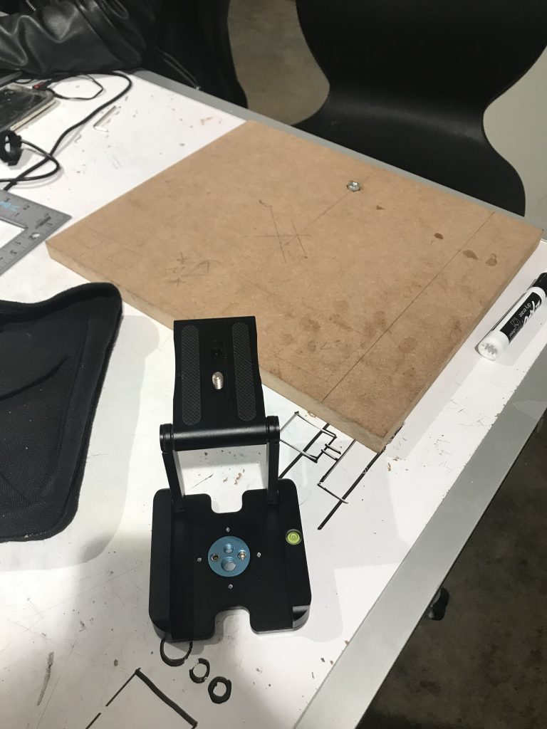
We initially tried to attach the camera mount to the board by inserting a hex nut into the board for the camera mount to screw into.
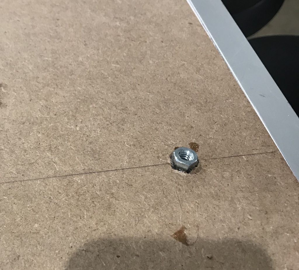
Closer shot of initial attempt to mount board to the camera equipment w were using as a joint. WE tried to embed and glue a nut into the MDF.
Discussion:
Many of the challenges we faced during this process involved getting the right parts to mount the board on. We knew that finding a combination of parts that allowed easy movement using a joint that wouldn’t collapse under the weight of the board, while positioning the board in a way that it wouldn’t tip over or rest too high above whatever surface it was placed on would be difficult, so we tried to focus on the mechanical aspect of this prototype. It took us a long time to find the right parts to order for the joint, which delayed our finding a good way to attach the joint to the board properly, and multiple different iterations of how Richard would interact with the LCD interface delayed us in getting a functional electronic prototype.
In order to be able to use the LED displays already available in the physical computing room, which display text in clusters of pixels and can only allow text inputs in a constant size, we created a system with 7 buttons, allowing us to have a constantly defined button for each conceivable purpose, including three buttons labelled as three different projects. Initially, we envisioned the working projects as simply being numbered as project 1, 2, and 3, but then decided that, as a record of previous projects would be an important part of the purpose of tracking the time for each project, when a project was completed, the next project should be labelled #4 and so on. Because the buttons for project 1, 2, and 3 were to be labelled with those numbers and placed in order, we reasoned that this would be confusing when, for example, project 2 was completed and the list became 1, 4, and 3. Additionally, past the first few projects, the numbers corresponding to different past projects would no longer be reasonable to remember, so we decided to add a method of naming each project. We looked for Arduino compatible keyboards, but decided that that would be an unnecessarily large component that would not fit into our already designed dimensions of the physical board. Instead, we added a rotary encoder, programmed to enter text letter by letter. We also decided to purchase a TFT display, and created code that would allow each button to be labelled on the display, allowing us to cut down to 3 buttons.
While during the presentation we didn’t have much time to get questions from the audience, we got helpful feedback from Richard regarding ways to make the form easier for him to use, such as adding a finger slot to the side of where we milled a place for his Apple Pencil to rest, and rounding out the right edge of the board so that his forearm wouldn’t chafe when he was drawing. He experimented with angles at which he would usually hold the iPad, and found that the fit was secure, but asked if we could add elastic on corners or hollow out the space below the top edge for a snugger fit on top when the iPad is at a high angle. We also were able to ask him more specific questions about his habits around taking commissions that we weren’t able to ask during our initial meeting because we hadn’t fully settled on an idea to probe more into the behavior around it; for example, he told us that he works on around 5 at a time, and would like to have them labelled in the system, supporting our choice to shift from constant buttons assigned to three projects at once to a menu system.
It would have been helpful for us to have at least some of the circuitry and software finished so that we could see if he felt comfortable interacting with it, and able to understand the basic mechanisms and instructions to use it. While we showed him paper sketches of what the interface and surrounding hardware would most likely look like and how it would be used, and he showed no issues in understanding how it would work, it would have been helpful to have had some part ready for him to interact with. Often hearing how something will work is easy to understand, actually using said thing is often when problems arise.
Our next steps include deciding on a final form factor for the board and creating the electronic interface. The arm mechanism has been finalized at this point, so we need to either find or design a bracket to interface with the holder. Next, the electronic aspects and layout need to be finalized in order to decide a final form factor for the holder. Code has been written and compiled but not physically tested, due to not having built the circuitry that would allow it to operate, which we will be able to do once we receive the new display. Once the electronics are taken care of, the test board will be milled and the prototype assembled to verify that the form factor is satisfactory. We plan to meet with Richard before the final critique to make sure that he is happy with our functional prototype before we move to our final version. After this meeting, the final board and baseboard will be made and polished and the final product assembled.
]]>A few weeks ago we interviewed Gary, documented in a previous post, to understand his daily life and what type of device he may have a need for. Since our conversation, we have worked on developing a fitness device that measures differences in strength between two sides of the body. This post documents our process in developing this prototype, as well as the feedback we received on it from Gary.
Device Prototype
This device gives the user a way to quantify the strength with which they complete exercises with a resistance band.
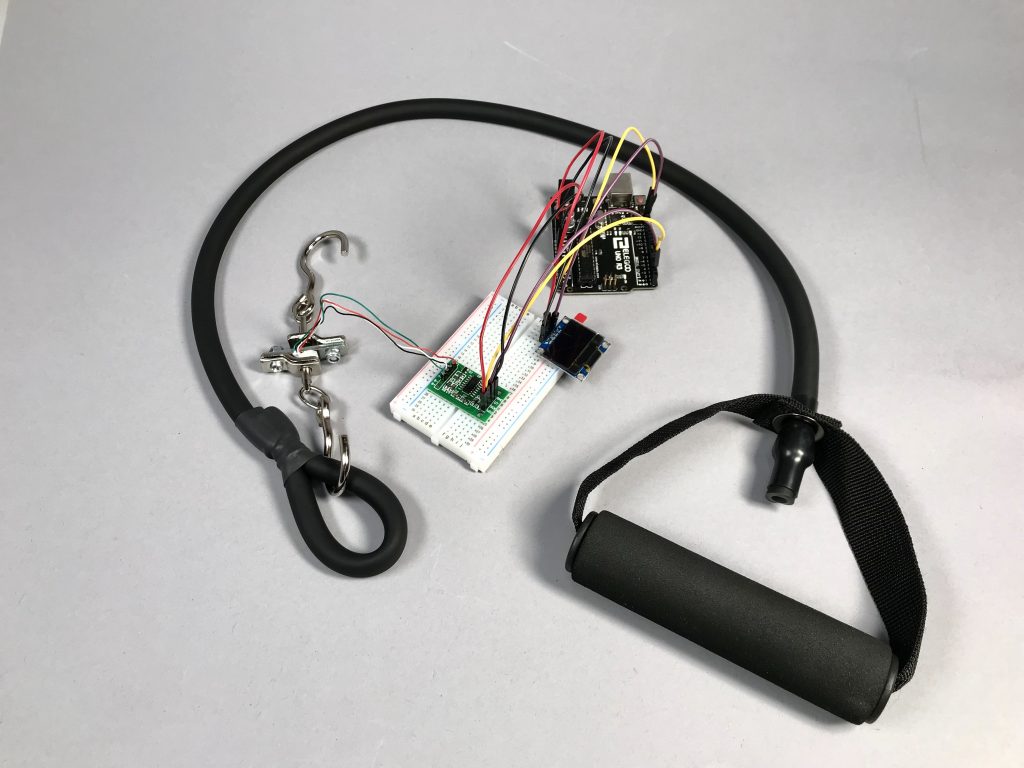
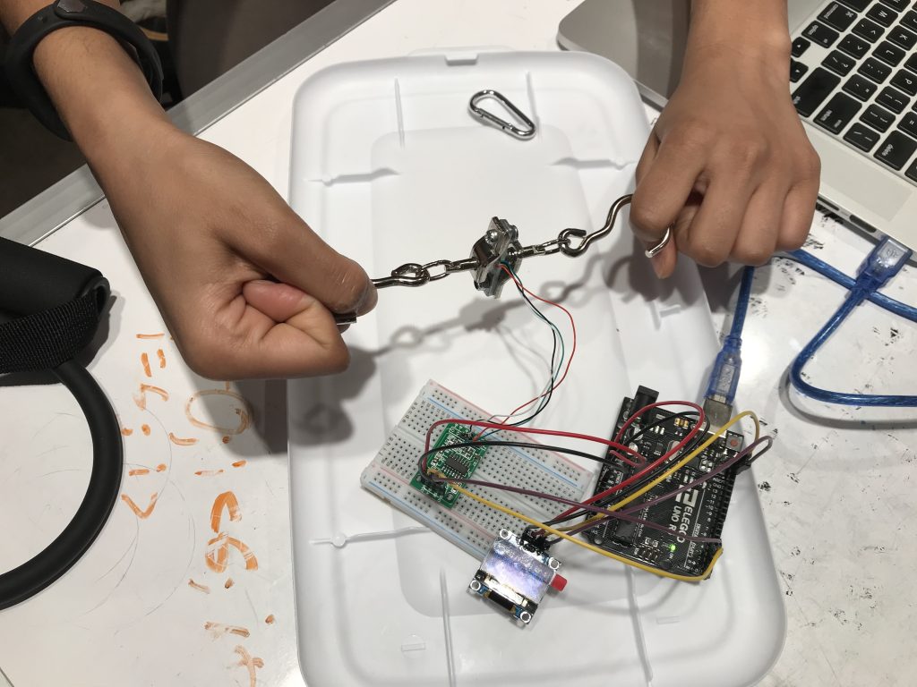
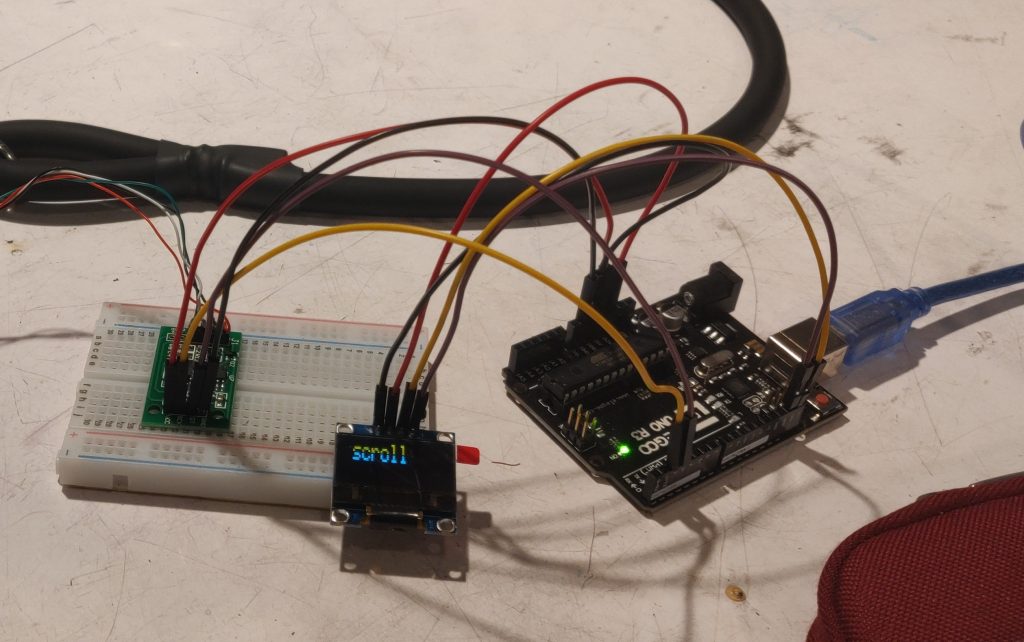
Overall photo of works-mostly-like prototype. The modified resistance band connected to the load cell, and the OLED display where output is shown.
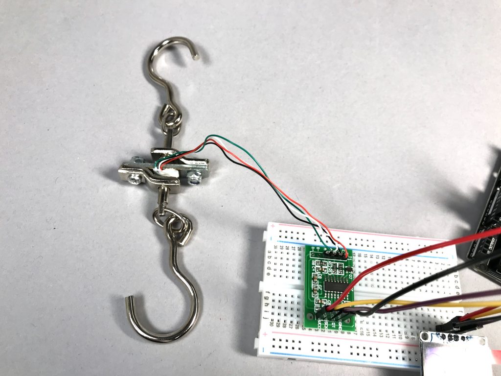
The load cell sensor with two hooks attached, wired to the amplifier board that sends values to the Arduino. This is our method of data collection.
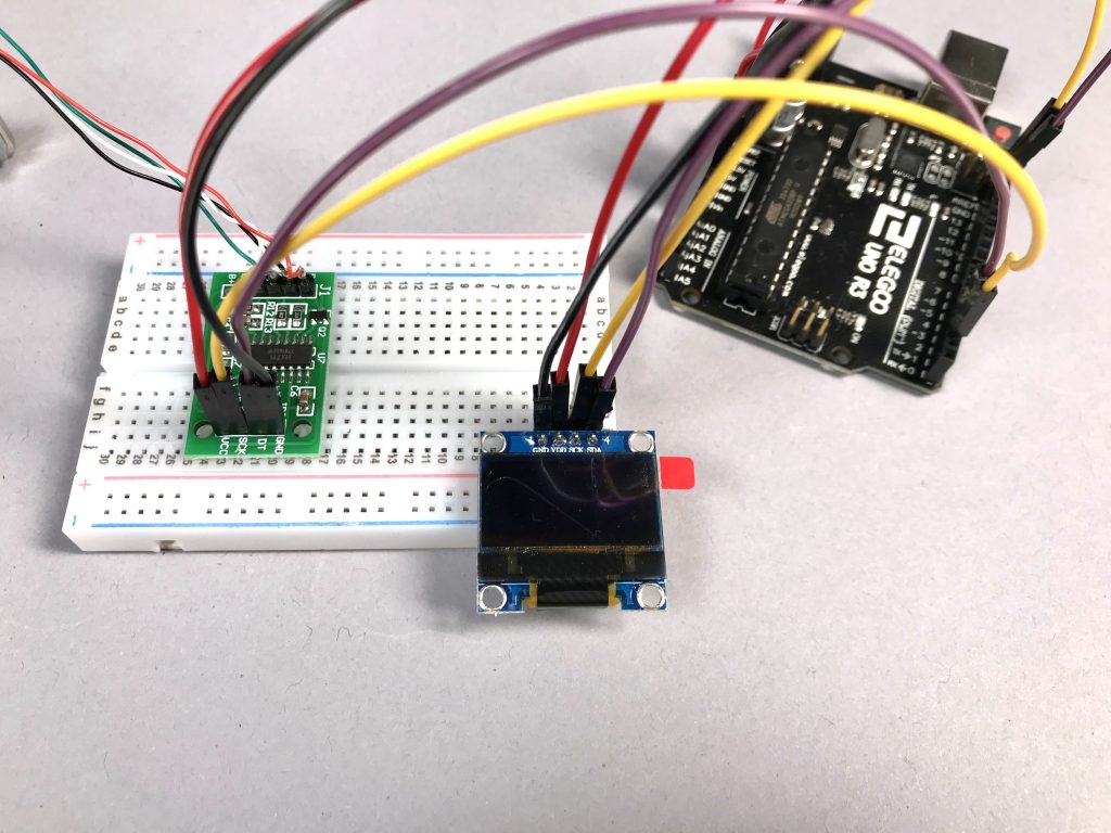
We decided on an OLED display over an LCD display, for a more compact and lightweight user interface.
The prototype is straightforward to use and interact with. One should begin by attaching one of the hooks to a fixed point, such as under a door or weight bench, and attaching the other to the resistance band. Once the user turns on the device, and the screen prompts them to “Begin”, they have 10 seconds to complete repetitions of the exercise they are doing. (This length of time was chosen arbitrarily, but upon further consideration we aim to make this controlled by the user in our final product). Then, once time is up, the screen displays the maximum force exerted during that time, and there is a pause for the user to change the side they are exercising. The user can continue this process, and thus gain a quantified understanding of the difference between their two sides or between multiple repetitions.
Process Images
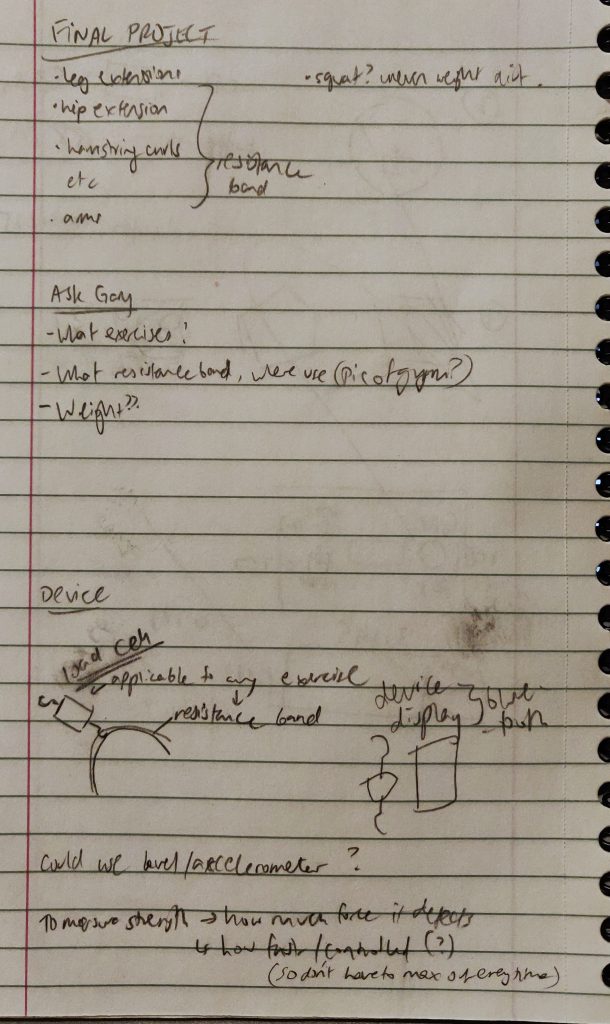
Notes made after meeting with Gary, sketches of initial ideas and possible features of the device we envisioned.
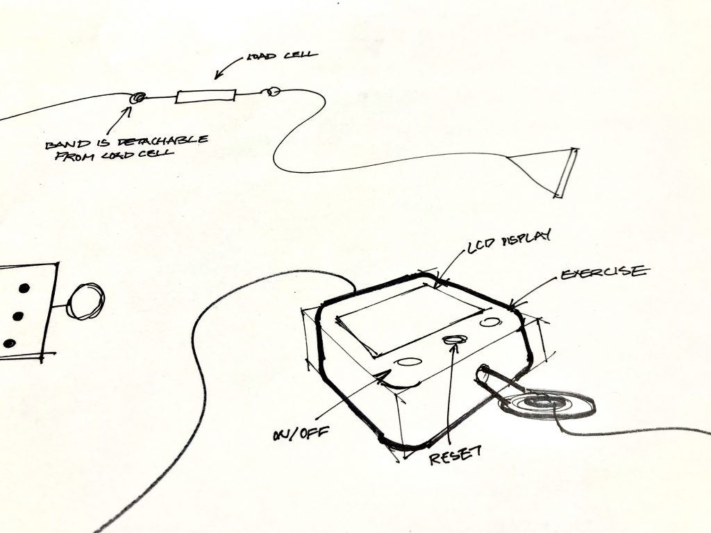
Early sketch of a possible physical form for the device, with possible functions for buttons and idea for attaching resistance band to load cell. We later decided to connect the load cell directly to the device, however.
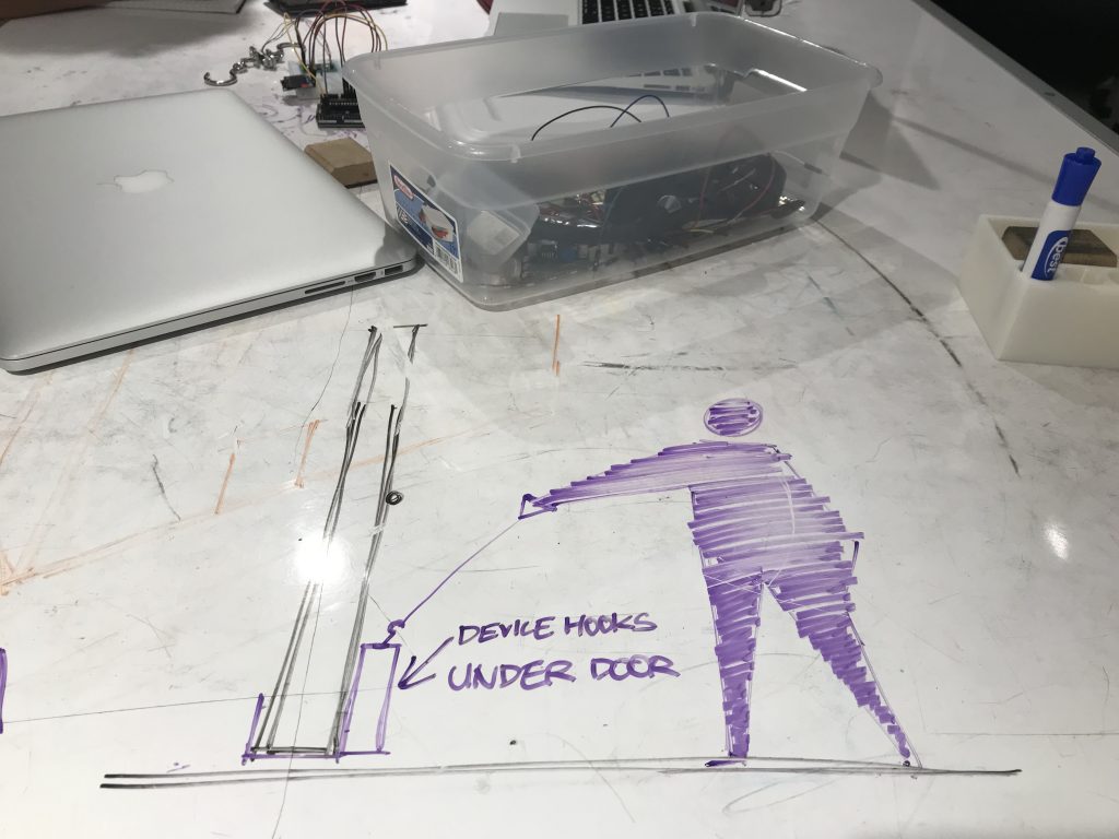
A more contextualized sketch of how our device can be adapted for Gary’s needs. The load cell can be anchored either in his home gym setup or attached to doors for travel and versatility.
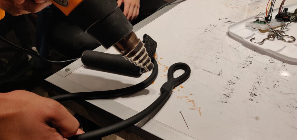
We cut a resistance band in half and shaped it into a loop, so that the load cell could hook onto it easily. Used heat shrink to secure the loop.
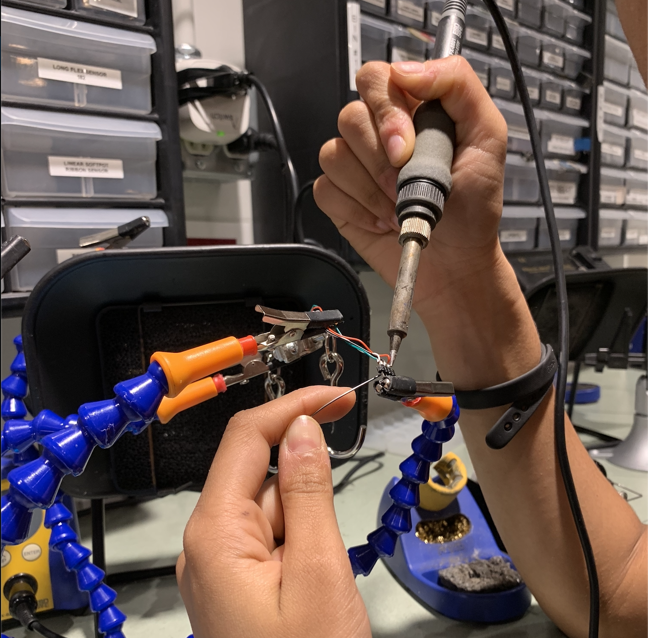
We soldered the load cell to the male headers, which eventually be connected to the load cell amplifier. The wires were extremely thin and prone to breaking, so the soldering had to be durable.
Testing the load cell, how different calibration values affect output. Our readings were initially precise and seemingly accurate, but were more unreliable the next time we used it. This was due to bad soldering and connections; once resoldered, the readings made more sense.
Testing the OLED display; spent time making text display in a format I wanted.
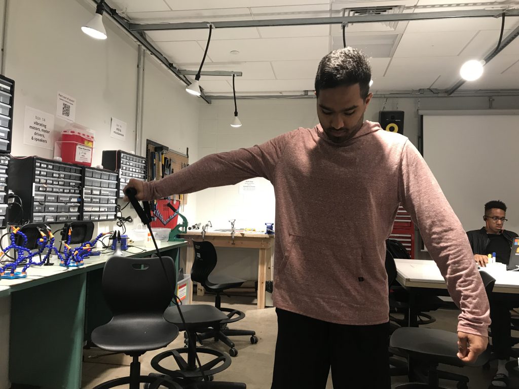
Acting out a use of the prototype by hooking the load cell underneath the table. It worked, so we decided to try and make sure the physical device could be adaptable to different surroundings.
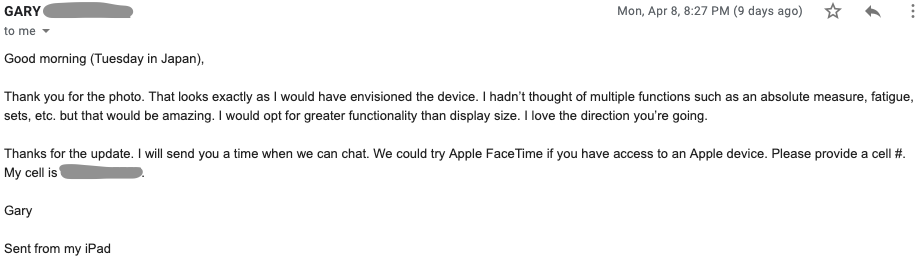
Since Gary wasn’t able to make it to our prototype critique session, we sent him our progress over email. Soon after receiving this email, we were able to speak with Gary over FaceTime in order to show him more in depth progress and get great feedback as to what next steps to take.
Discussion
Design and hardware implementation were our primary challenges. As we began designing, we had to figure out exactly how we would anchor our project in Gary’s home and how we could achieve multiple ranges of motion with a single device. We also recognized the challenge of housing the device to be both compact and extremely durable. Finding a load cell that was the right size, could be positioned in all 3 dimensions, and could be easily interfaced with was a challenge as well. We eventually found a cell that integrated well with our Arduino, but the wires connected to the actual sensor were uncomfortably thin and prone to breaking, especially because testing required the load cell to be moved and stressed constantly.
Gary wasn’t able to make it to the crit on Monday due to a family trip to Tokyo, but we had an audio call the day after to discuss our progress. He had some questions for us regarding the use of our prototype from the pictures we sent him, but he expressed strong support for the direction we were heading in. He liked the use of a resistance band instead of an unyielding, fixed rope and the way that this allows for 3 dimensions of movement.
One idea Gary gave us that helped clarify our future plans was the distinction he made between maximum and fatigue exercises. He wants to be able to tell the maximum amount of weight he can lift with both sides of his body as well as the amount of repetitions he can do until fatigue, while our current code only tells the user the maximum force. We recognize detecting fatigue in exercise sets to mostly be a software issue, which can perhaps be addressed by taking the average force reading over multiple repetitions of the exercise. Other than this, however, Gary just reiterated that he liked our ideas; we didn’t receive any negative feedback or ideas to prod us in a different direction.
Moving forward, we have decided how we’d like the interactions between the user and the device to work, in terms of buttons and their functions on the device. Gary expressed interest in being able to quantify the strength of his weak side against that of his strong side, so we plan to include more data on the screen between sets of exercises (such as average readings, maximum readings, the readings as a percentage of past readings, etc.)
We plan to implement these ideas in significantly more detail in the next week, as well as figure out which materials and design we need to guarantee durability of our device. Once we have a more complete user interface, including buttons and the screen displaying more relevant data, we hope to also have a reasonable looks-like prototype at the end of the week. Then when Gary returns from Japan, we plan to reach out to him for more feedback on the device, and perhaps give him the opportunity to try it out in person as he couldn’t do so on Monday.
]]>
Prototype
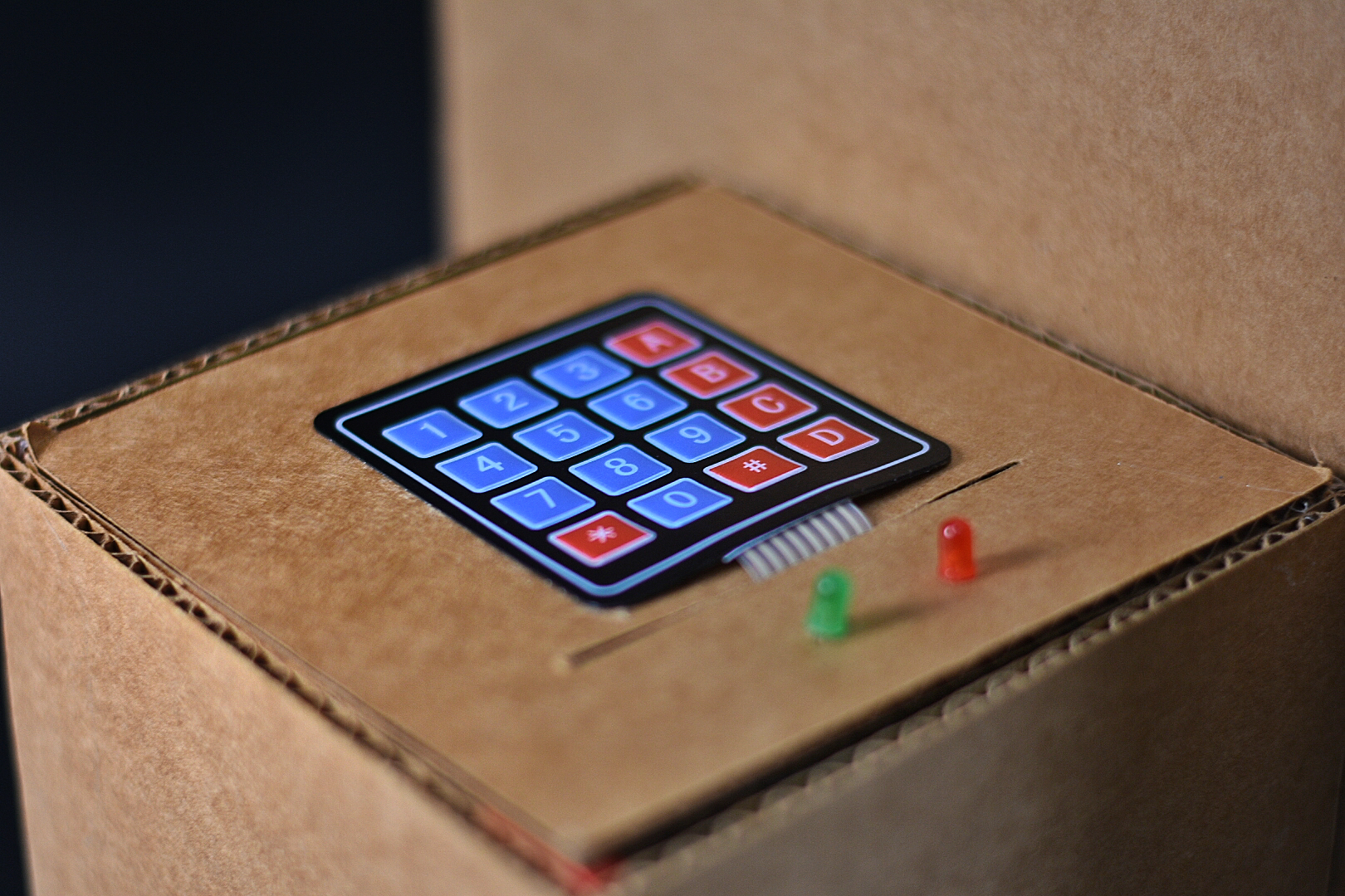
They keypad with LED indicators for (in)correct password

Pretend package full of marbles to be used in demonstration
Introduction
This documentation presents the prototype of the anti-package theft for Emily. We interviewed Emily which is detailed in an older post and have detailed a working prototype that both looks like and works like the final product below.
Prototype Explanation
The purpose of this prototype is to fix the issue that Emily has of her packages often being stolen from her porch. This prototype doubles as a stand for her to keep her groceries on when she has to unlock her door so she doesn’t have to drop them and bend down to pick them up afterwards. This box has a lid that is normally closed and unlocked and will be opened when a delivery person comes. Inside are force sensors that check if a package has been placed on the bottom surface. There is a set time to wait to make sure that the force is constant to prove that it is a package and not some animal that has weaseled its way inside. Afterwards Emily will enter a password that she has previously set into the keyboard in order to unlock the box to retrieve her package.
Process Pictures
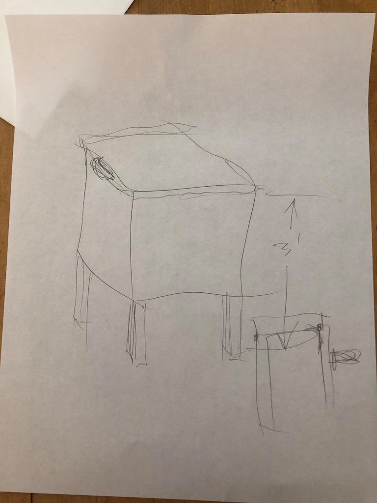
Our initial device drawing, showcasing a rough outline of our initial idea of the device’s look.
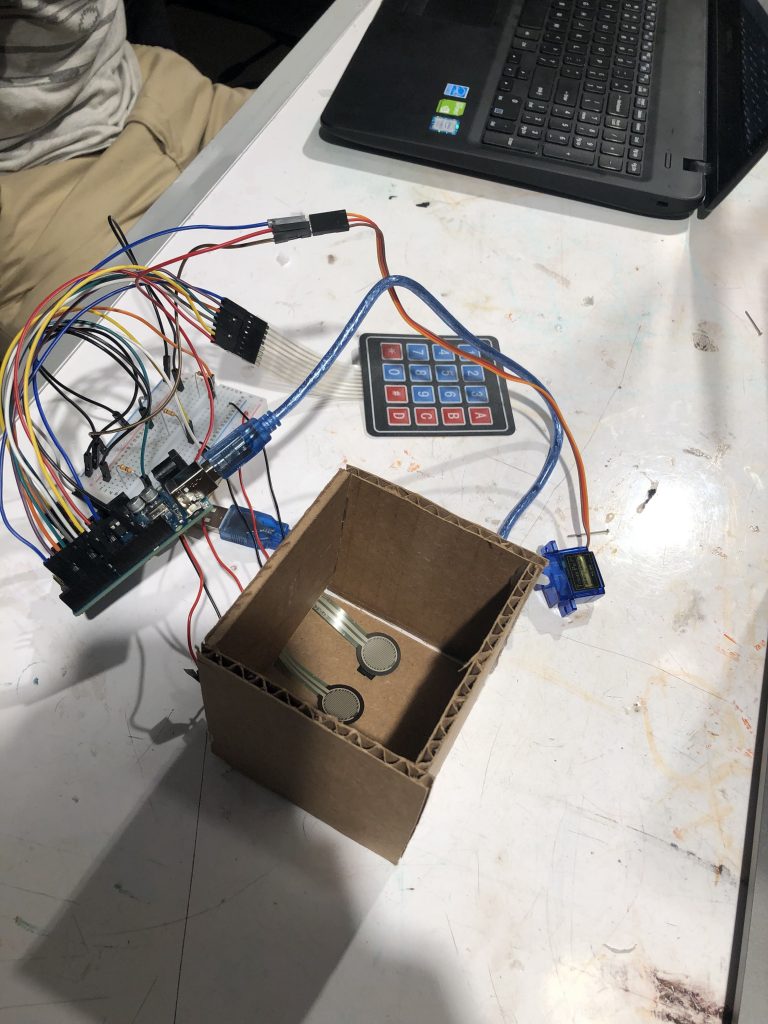
The preliminary prototype. All components (aside from LEDs) are integrated rudimentarily and working as they should.
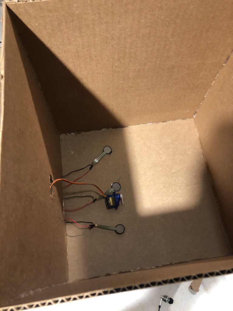
Transfer of pressure plates to prototype. We tried to maximize the distance between each to cover a large amount of surface area.
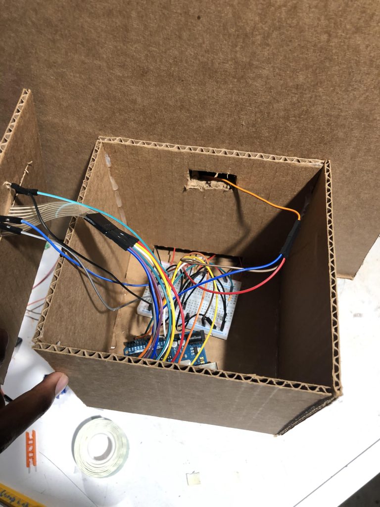
Our prototype’s main hardware housing. We wanted something simple that made the core wiring invisible to the user and large enough to fit everything in one place.
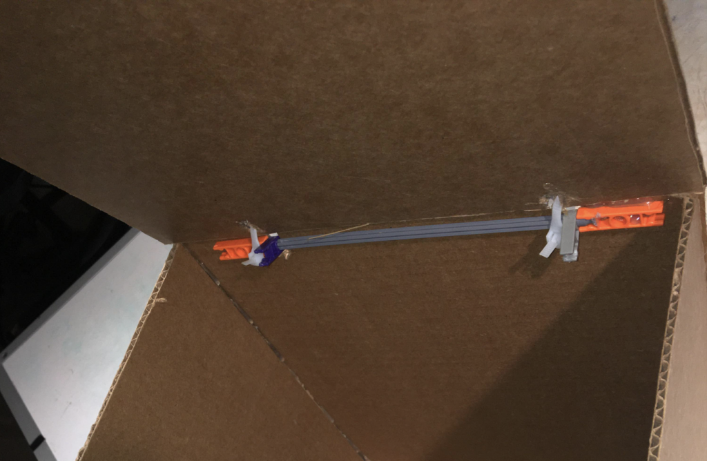
Our prototype’s roof hinge system. We initially tried to use k-nect components but changed to plastic string when k-nect components proved very finicky and unreliable.
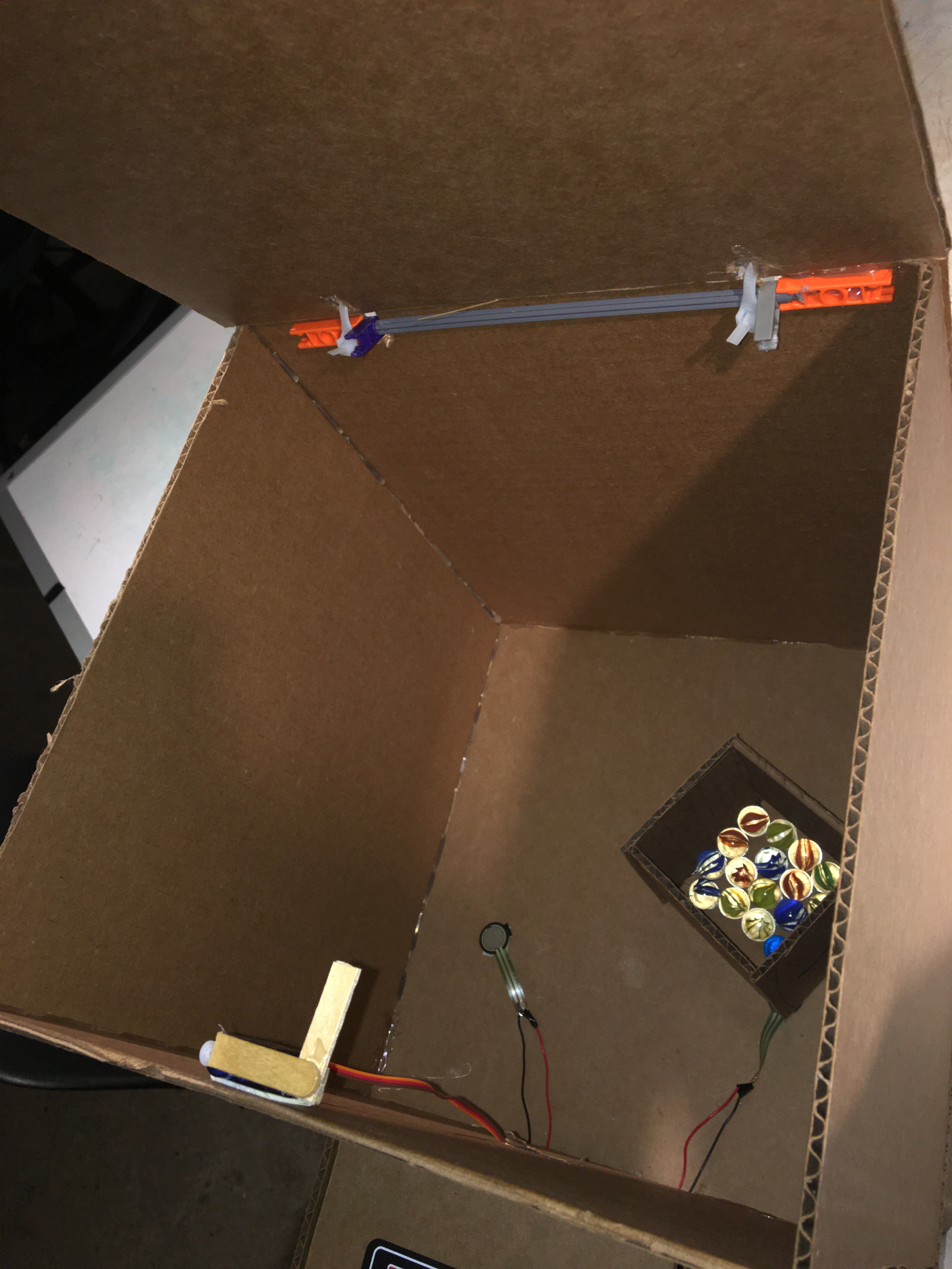
Overhead shot of new hinge, pressure sensors moved, and new lock piece on servo
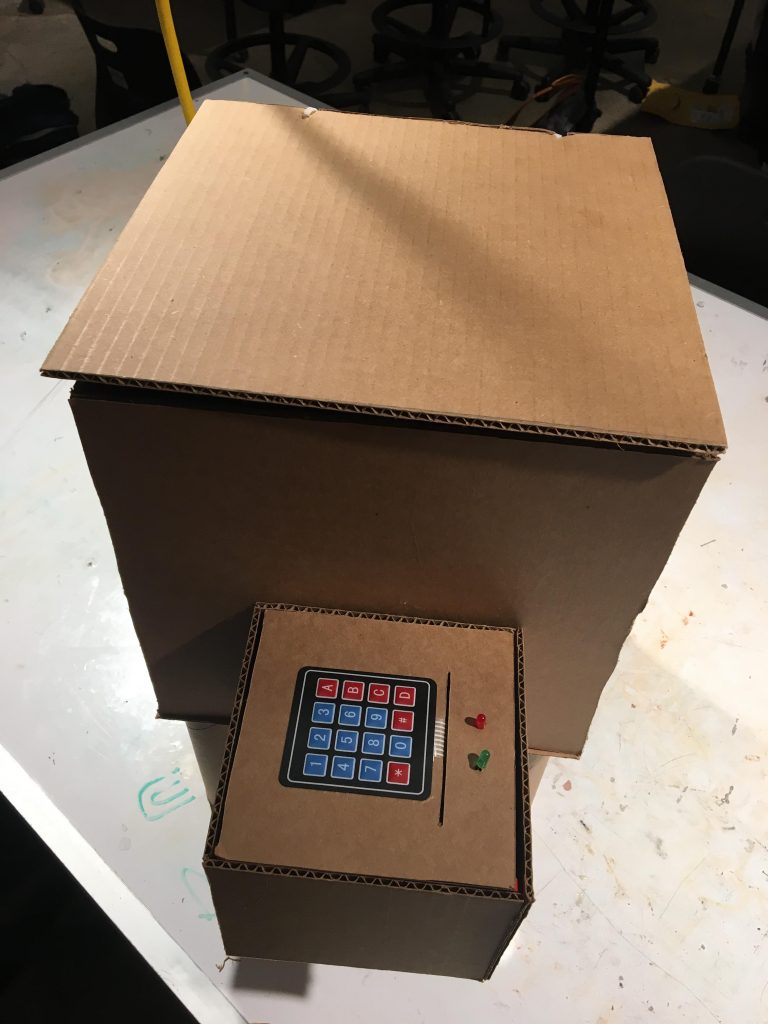
The completed prototype. It is approximately 1:3 scale of what the final will be.
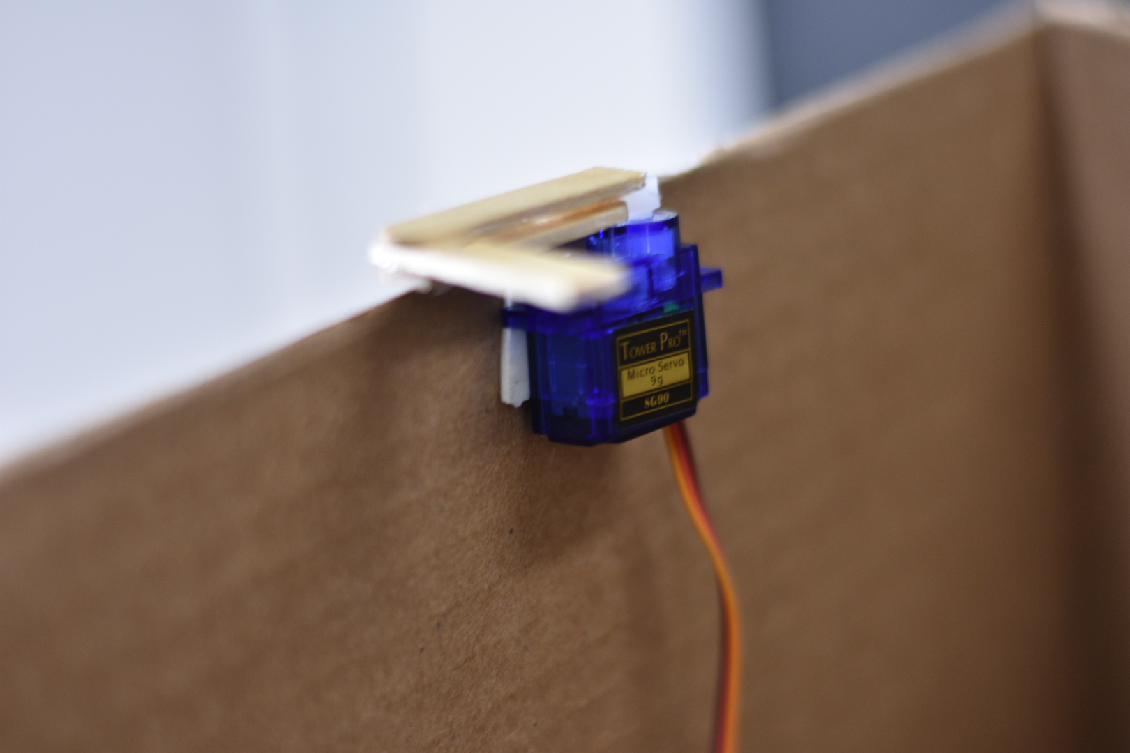
The servo used with an L-shape lock from popsicles.
Discussion
Challenges:
Throughout our prototype creation we faced several challenges: obtaining a working device passcode check system, designing a functional and reliable lock, and identifying sources to behavior abnormalities in our device.
At its core, our project is an anti-theft device, and so the ability to distinguish between adversary and benign users is critical to a working produce. Though many solutions exist, we opted for a simple keypad passcode as the identifier due to the readily available soft and hard keypads in the class lab. Initially, we found implementing the keypad logic fairly straightforward as each each pad button was represented by an element in a two dimensional array. However, we encountered difficulties when trying to check if two combinations matched. To explain, our reference code we used suggested to encode both combinations into string format, and then use a string compare to determine whether the two matched. However, when doing this we consistently found that one string was equivalent to the concatenation of the two combinations, while the second was a single combination. To illustrate, if the two combinations desired to be compared were: ‘1234’ and ‘1234’, then under string compare one string would read ‘12341234’, while the other ‘1234’, thus returning ‘False’ when in fact it should return ‘True’. This result was exacerbated by the fact that nowhere in our code was there an operation which concatenated the two combinations. However, through further experimentation we realized that what was most probable was that the issue was caused by the strings being stored right next to each other in memory, and that this was causing one combination to be read as the concatenation of two. Thus, to counteract this problem reliably, we opted to do an iterative-wise character compare which worked significantly better.
Another big challenge we faced was designing a functional and reliable lock system for our prototype. Though as with user type identifiers, there were many possibilities, we thought the simplest lock would be an L-shaped lever which would turn into a hole to lock. This would allow us to use a hobby motor as it primarily creates rotation around an axis. However, integrating our locking contraption with our box created a few challenges. Firstly, we quickly found that not only was the motor’s rotation inaccurate (e.g. if we set the motor to turn 90 degrees, it would vary between turning between 90 and 120 degrees), but it also turned extremely fast which proved dangerous to the device’s structural components. Both these issues created challenges in the lock fitting. For instance, due to the unpredictability of the lever’s rotation, it could reach the hole just right and lock as expected, or push through the hole break the lock (with the help of the rotation speed). This latter problem actually became a reality in one instance when the lever overshot the lock hole, and tore the box top off its hinges. Thus, to mitigate this issue, we conducted several experiments to effectively gage the motor’s rotation error randomness before empirically finding a rotation value which would avoid breaking the device while still ensuring it would lock.
Our third big challenge, was identifying sources of behavioral abnormalities in our device. Our prototype can be thought of the integration of three hierarchical stages. The first is the physical stage which comprises of how a user physically interacts with the device. The second is the user input reading stage, which consists of reading and extracting information provided by the user. Lastly, the third stage entails understanding and performing instructions based on the information extracted from the second stage. Framing the prototype in this way elucidates the fact that when the device behaves abnormally, it can be challenging to find the root cause because any of these stages could be at fault. For example, if a user’s passcode input does not match the device’s stored passcode (to unlock the box the user must input the correct passcode), the root of the problem could be (in respective order of the stages): 1) the user has put in the wrong passcode, 2) the user has put in the correct passcode but the keypad was faulty and did not accurately record all button presses, or 3) the passcode was correct, the keypad is reliable, but there is issue in the software passcode comparison. Because of this, whenever an abnormality arose throughout our project prototyping we had to debug each stage separately before identifying the cause (in the case of our motivating example it was a faulty keypad), which resulted in substantial loss of time. Though we have not yet found a more ‘cost’ effective way of debugging, it is something we’re interested in exploring for the final product.
April 8th Critique:
During the critique with Emily on Monday, we went over our ideas and prototype for what we had so far. Emily appreciated the overall design, however she had some ideas and changes that we could work towards for the final. The prototype has issues with the keypad being too fidgety and difficult to control, it was also not water proof. For the final, Emily hopes the keypad to be made of metal and to be reliable and water proof. The sensors at the bottom of the box are not large enough to be accurate for such a large box, she hopes for the sensors to be larger and cover more surface area along the bottom so a small animal will also be able to trigger the sensors. Emily also wants the box to provide more feedback, perhaps a light indication when a password is successfully changed and a light to tell if there is a package in the box. We brought up a concern that she may receive more than one package delivery in one day, however she did not seem to consider that a problem, she said she rarely receives more than one package delivery a day. We are still planning to look into this issue however it is not critical.
Emily wanted to establish that the enclosure does not need to be a perfect box. In fact she said it might be better for the box to be longer rather than wider, that way the box won’t bulge out so far onto her porch. She gave us appropriate dimensions of 20″x18″x30″ high or alternatively 20″x20″x30″ high. Our team also discussed materials with Emily and we agreed that wood would probably be the best material to be water proof and inconspicuous. She stressed the importance of different wood joints that will stay strong for long periods of time, we are considering mitered biscuit joints but are still thinking of different options.
One large problem that Emily brought up that we did not consider is power. The box needs power 24/7 in order to check for packages and react accordingly. One idea that Emily brought up is solar power. She drew a picture of the back deck and showed how sun hits the area, she explained different places where we could wire a solar panel to the box to receive power. We brought up the idea of opening a nearby light switch and adding a connection to the box, however this is something that she would need outside help to do and she seemed to prefer solar power. She offered to be in contact with us about wire lengths needed and different physical aspects of the solar panel condition.
Next Steps:
Our next steps will definitely start with ordering new, better, and waterproof parts that we can start working with. Having the final parts will give us the upper hand on designing the full size box. Secondly, we will refine the box hinge and locking mechanisms to ensure that each is resistant to Pittsburgh weather conditions and working reliably. Thirdly, we will completely redesign the user interaction portion of the device: keypad and LED feedback. We plan on using a metal keypad in place of the soft button keypad, and introducing LED displays to give direct and more granular feedback for users. Fourthly, we will redesign our device to fit within the dimensions Emily specified, and investigate using solar energy to power the box. For this end, we will also stay in contact with her to understand the specifics of wiring needed for connecting solar power to the device.
]]>
With our meetings with Mark, we discussed what he would want or what he would benefit from the most. Mark enjoys to spend time in his kitchen and although he is in the process of making alterations to better fit his needs, something that he needs more help with is his oven. The criteria that Mark set out for us is that he needs something to put his baking trays on and off of/ in or out of the oven while also supporting the weight. Additional factors would be mobility and to be able to set it on top of a side table he has within his kitchen.
Physical Prototype
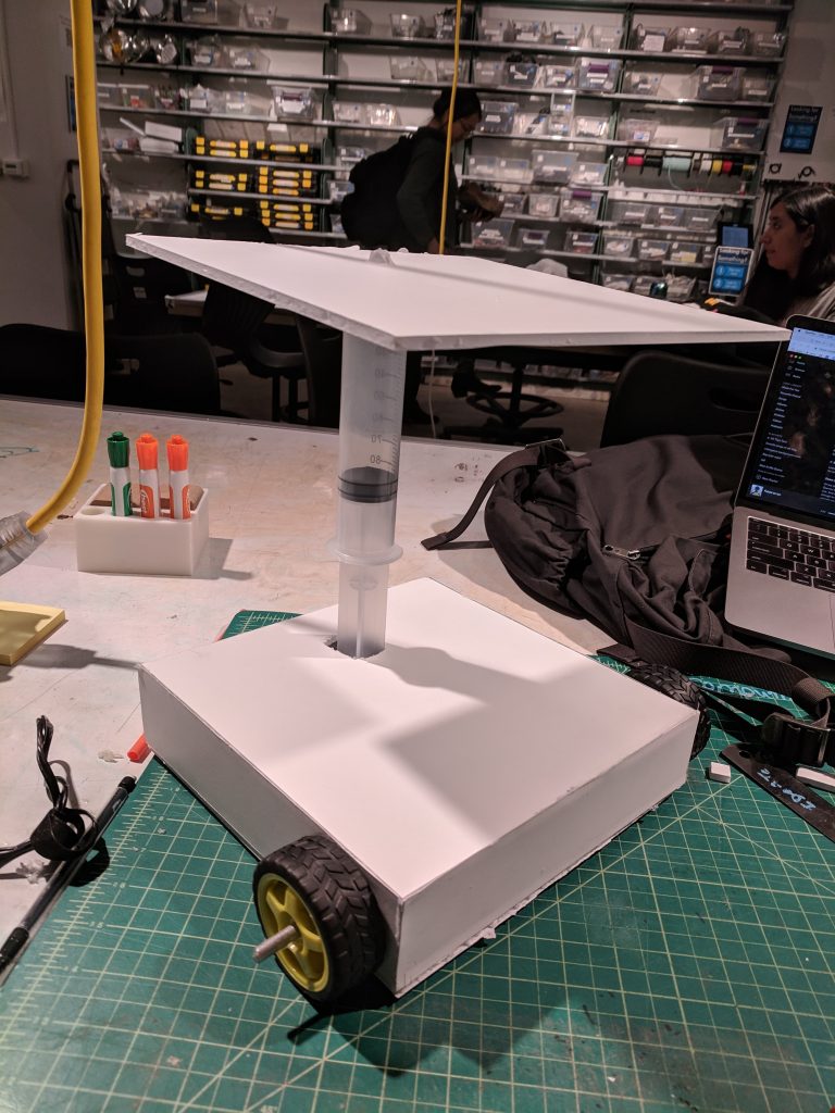
For the physical prototype we built something that would represent the form of the product as it needed to be a shape that would be able to fit under his over door while it was open, while also providing the height it needed to slide the baking trays on and off onto the oven trays.
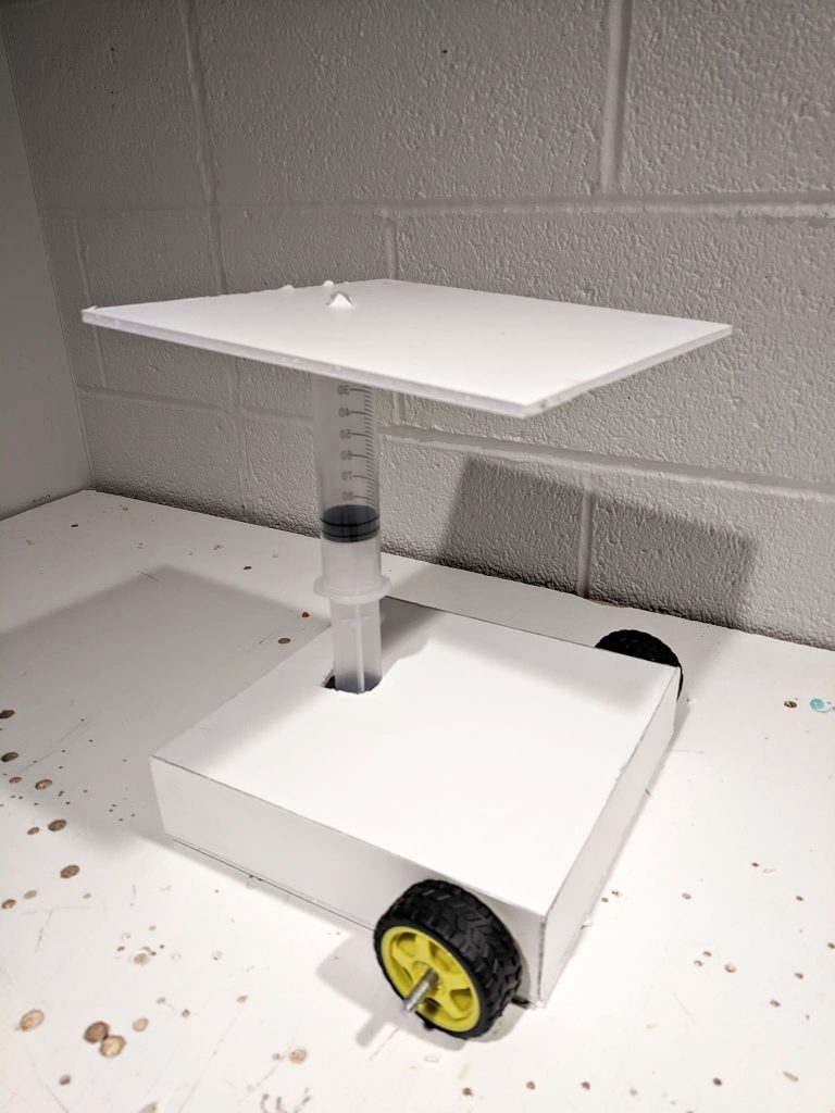
Also has wheels to allow movement, there will be 4 on each corner. Do not yet know where it will stick out on sides or from the bottom.
Here is a video of if working more as a “looks like” prototype with it going up and down.
Process
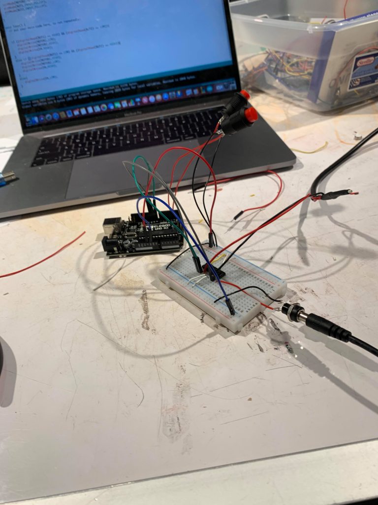
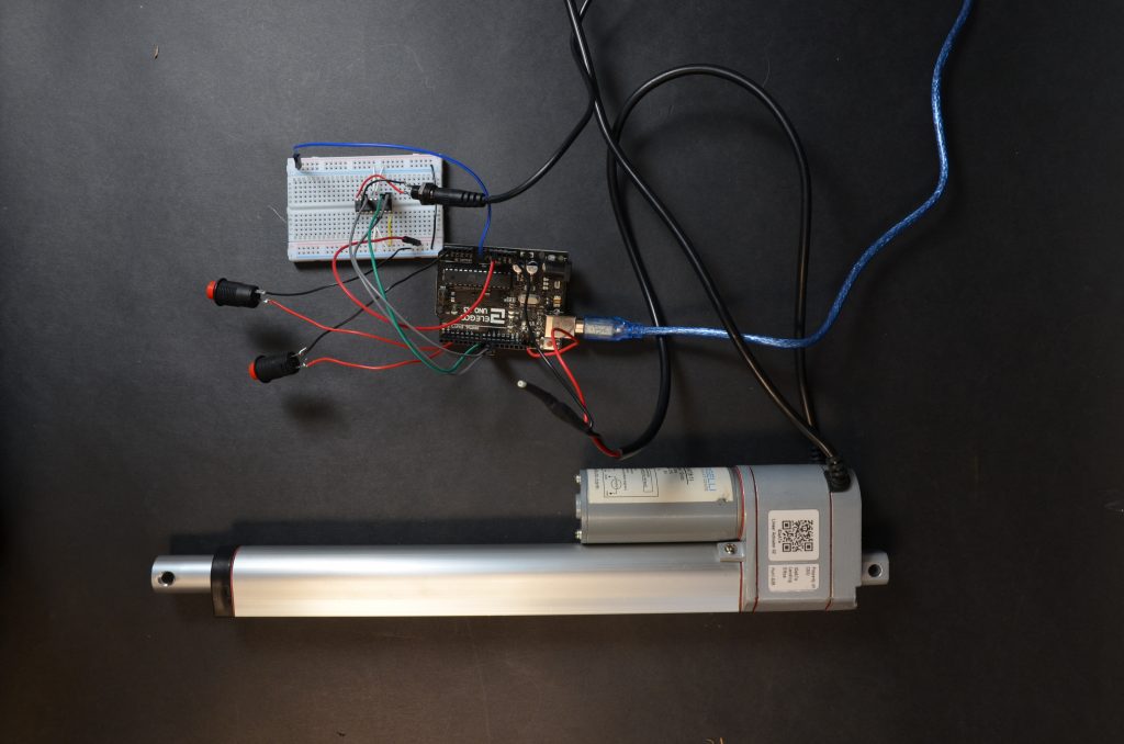
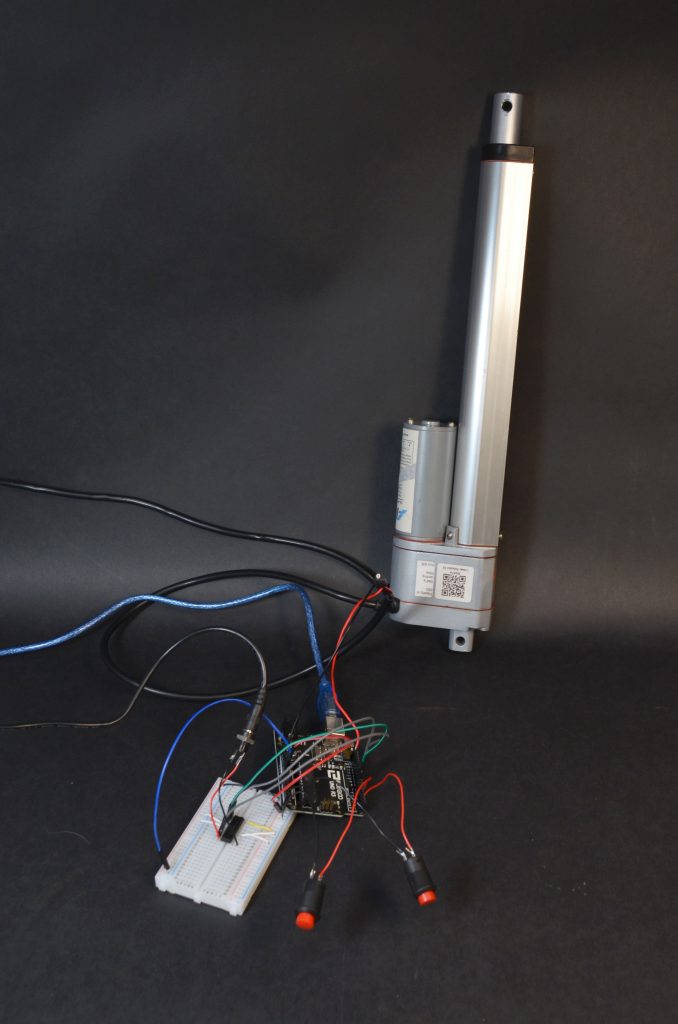
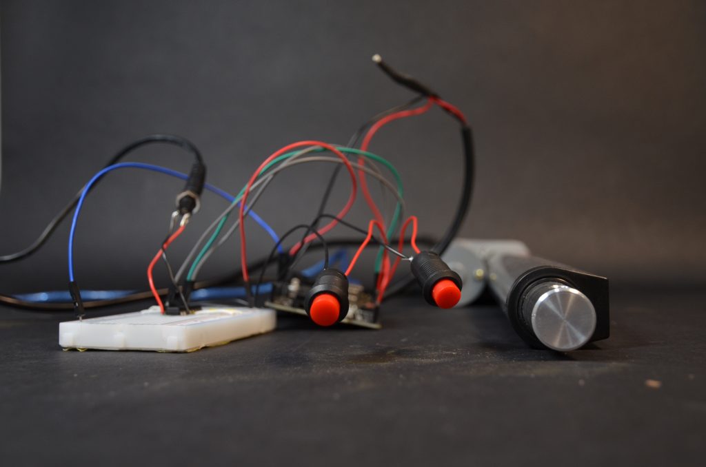
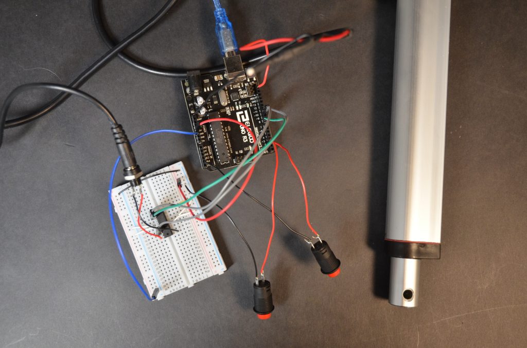
Wiring and coding the linear actuator with two buttons
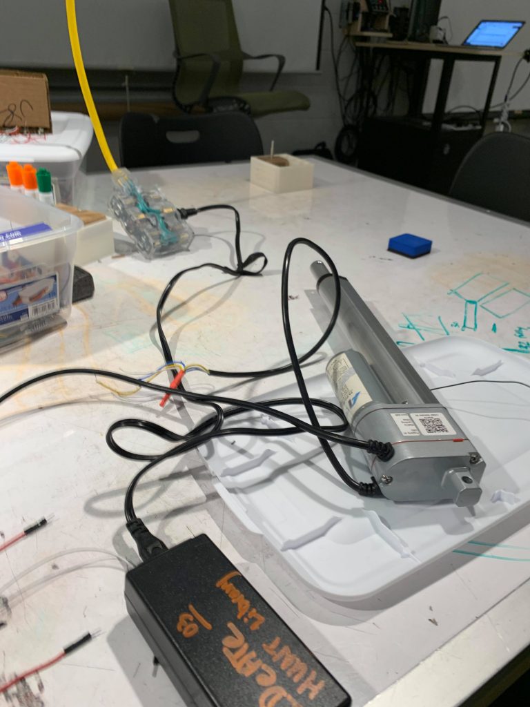
Linear actuator with battery
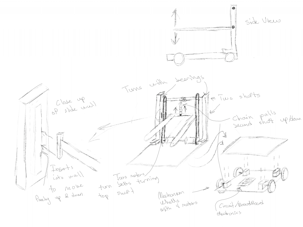
Drawings of how the linear actuator may work and the wheels
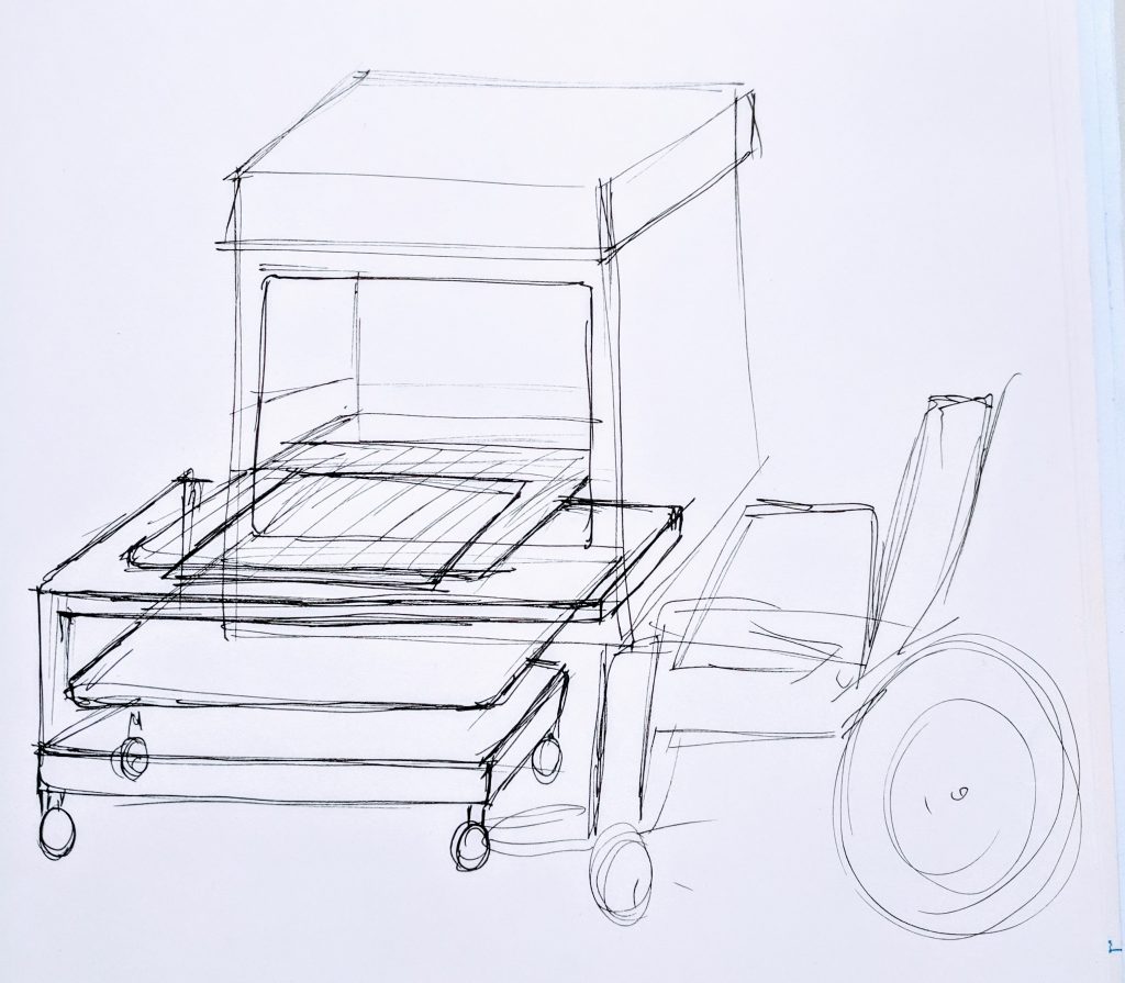
Rough sketch of marks wheelchair comparative to the oven and device
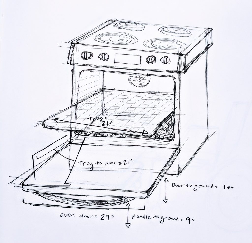
Measurements of the oven to make sure of physical prototype
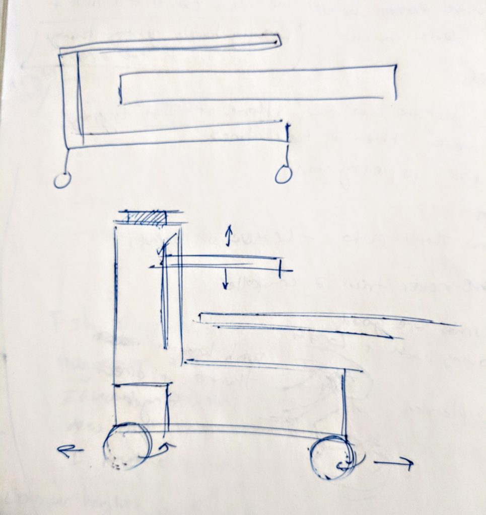
Sketch on how device would be situated relative to oven through side view
Modeling out of foam core and other components.
Our Final “Works Like” Prototype
Discussion
Challenges
A challenge that we ran into while prototyping was discussing, should we simply build a prototype that looks like or have a scale for it? Through this there were certain measurements that needed to be looked back upon and other design considerations needed to be made so we went without having to do it by scale. Another challenge was also trying to find something to imitate the movement we were looking for while also maintaining the shape we wanted. For the wiring part, it was a bit difficult to handle the different voltage for the actuator.
Talk with Mark
When presenting the idea and prototype to Mark, Mark was glad that he could imagine it actually working for him. During the discussion, Mark brought up the same points that we were discussing such as material and mobility of the device. Also, the tray design was a factor that Mark was invested on.
In the beginning of the talk, we had all agreed on having the device be mobile on omni-directional wheels, and having the device be made out of some sort of metal or heat-resistant material to be sturdy. A point that we discussed a lot about was the tray part of the device, in whether it should have sides or not. At first, we discussed why sides might be more good than bad, but Mark had inputed he wished there to be no sides at all. So we discussed further, and decided to lead towards the direction of having a platform that wont slide of when needed to. This input helped us greatly into moving to a different design thinking that was more suitable for Mark, rather than just one of our ideas.
Future Plans
We plan on researching about more material as well as implementing Marks comments on mobility and having a surface that wont allow the tray to slip off. This will require to explore more about the form of the tray portion of the device. Another factor that we are thinking about is what kind of handle it should have along with the placement of various things such as controls on the body of the device. For future plans, more sketching and communication with Mark will be involved as well as another home visit to finalize dimensions so that we can think more about what materials would fit best for this device. Along with this, we ordered a part(a longer linear actuator), which will be considered within the sketches/dimensions as well.
]]>Prototype
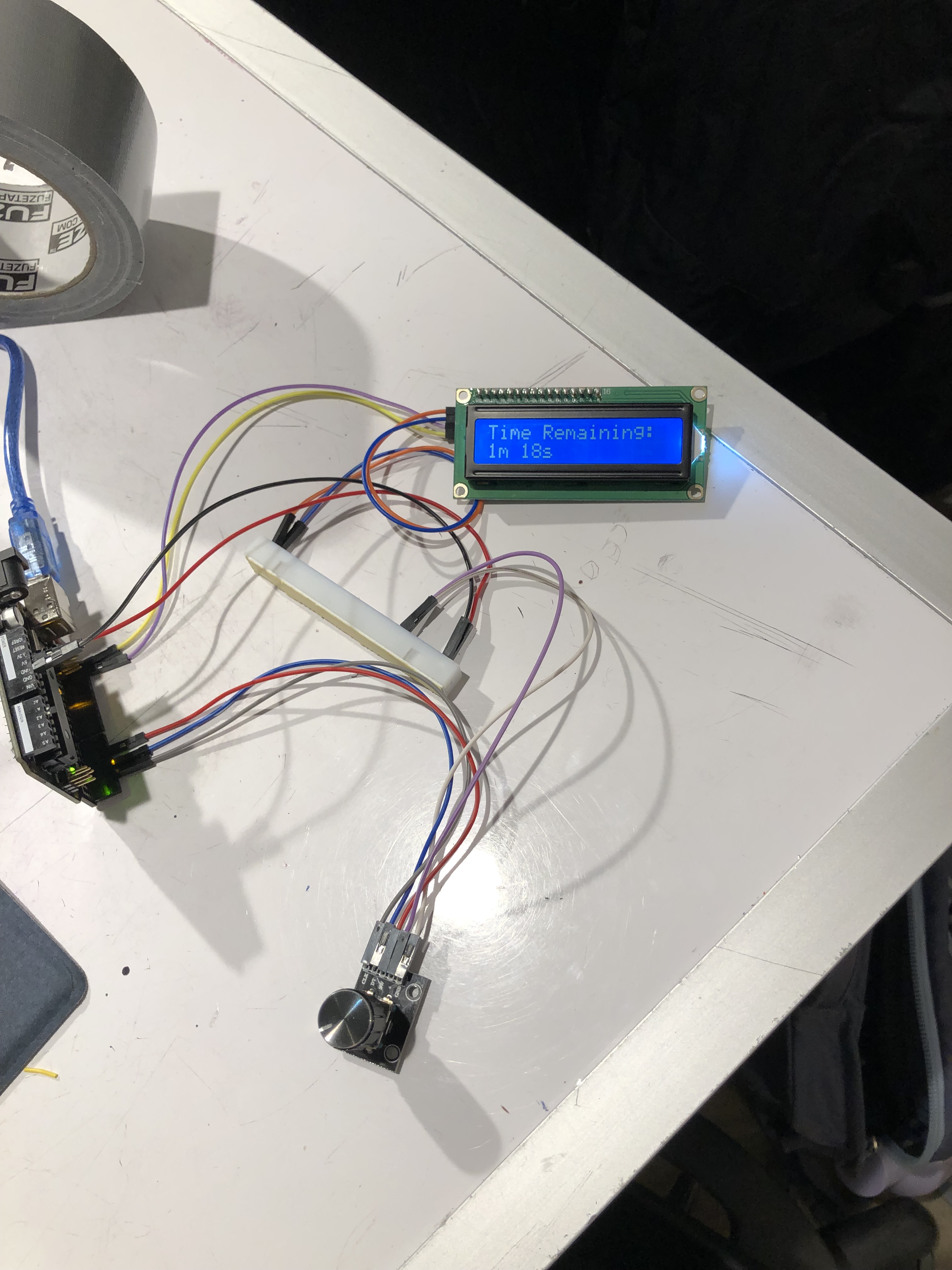
This prototype’s behavior is exactly how we intended to implement the final device’s functionality. The rotary encoder allows the user to spin the dial to set the amount of time that the light will stay on. The time being chosen is displaced on the LCD display and then the countdown until the light will be switched off is displayed once the timer has started. Pressing the rotary encoder starts the timer. There are also two manual buttons: one for turning the switch on and one for turning the switch off.
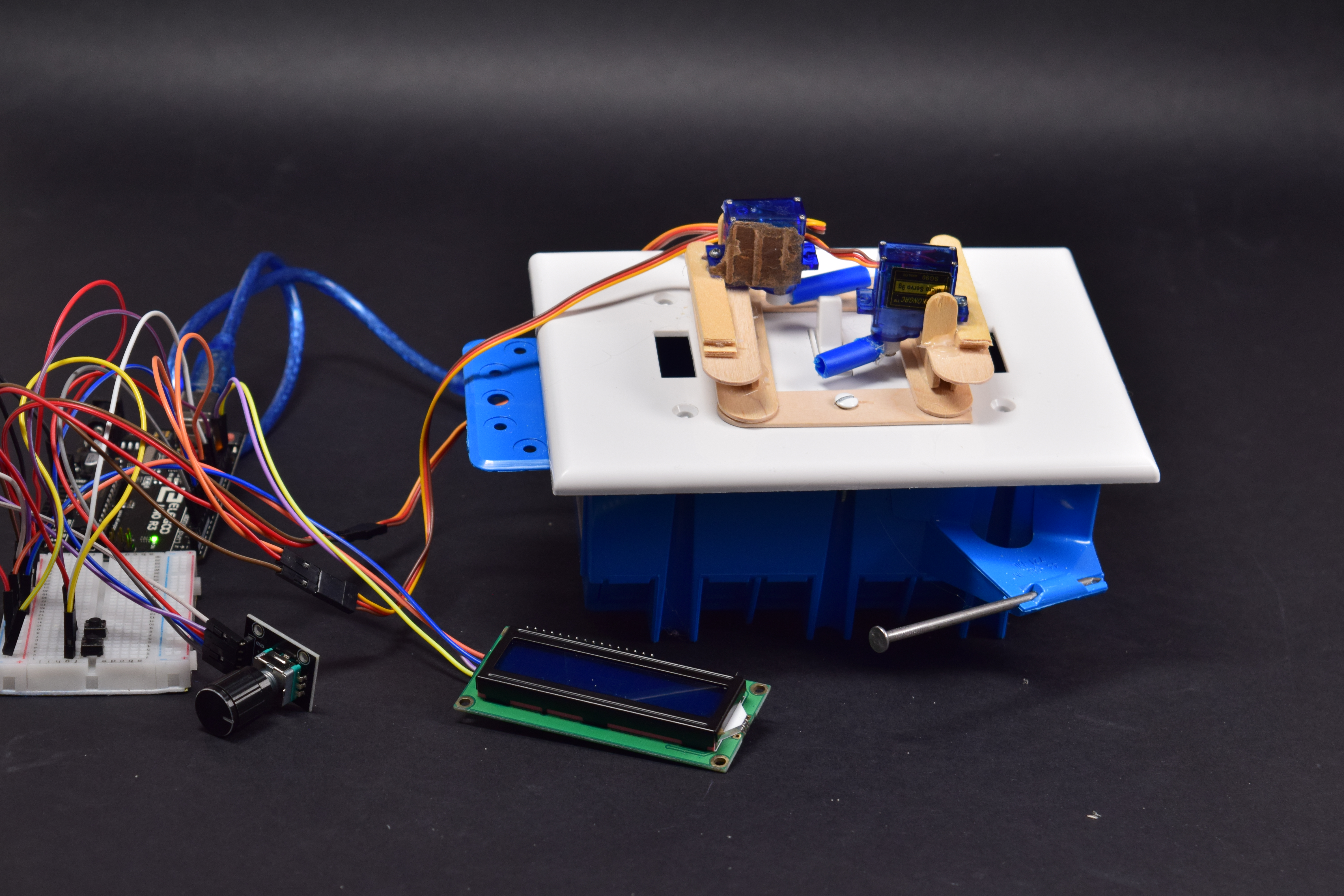
Full prototype
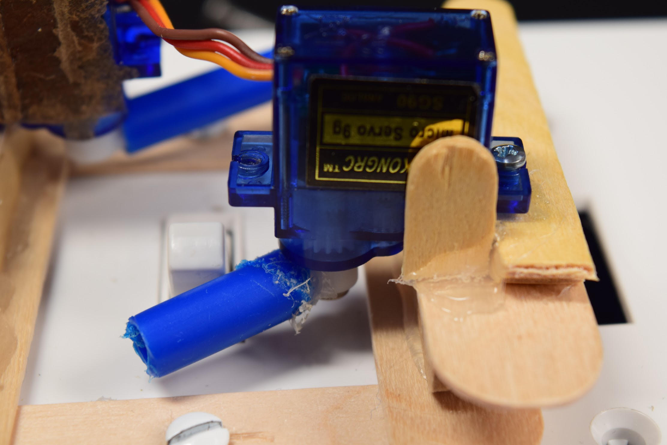
Closeup of the servos used
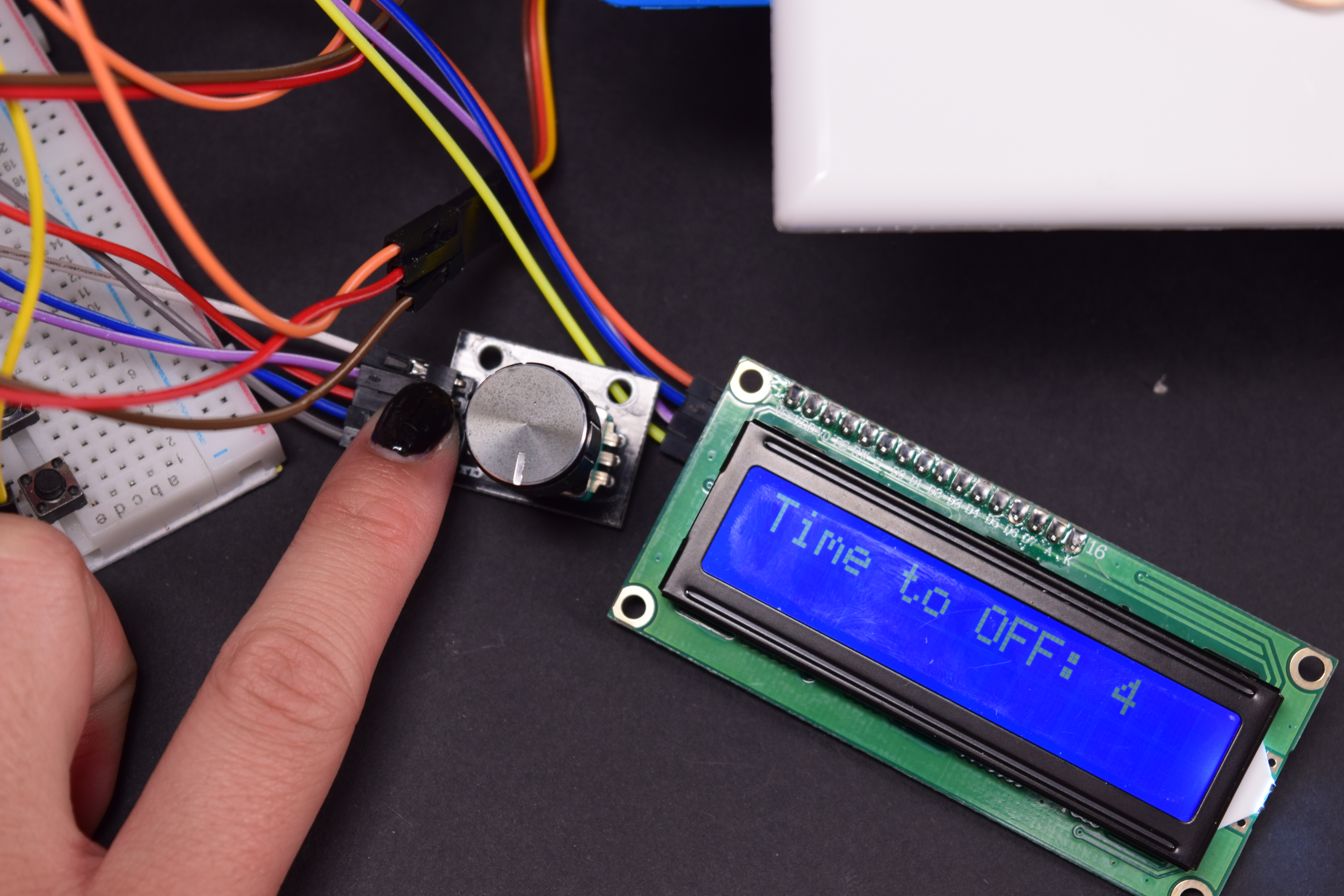
The user interface: LCD display and rotary encoder for setting timer
Process
We got the LCD screen to display the time until the light will be switched off.
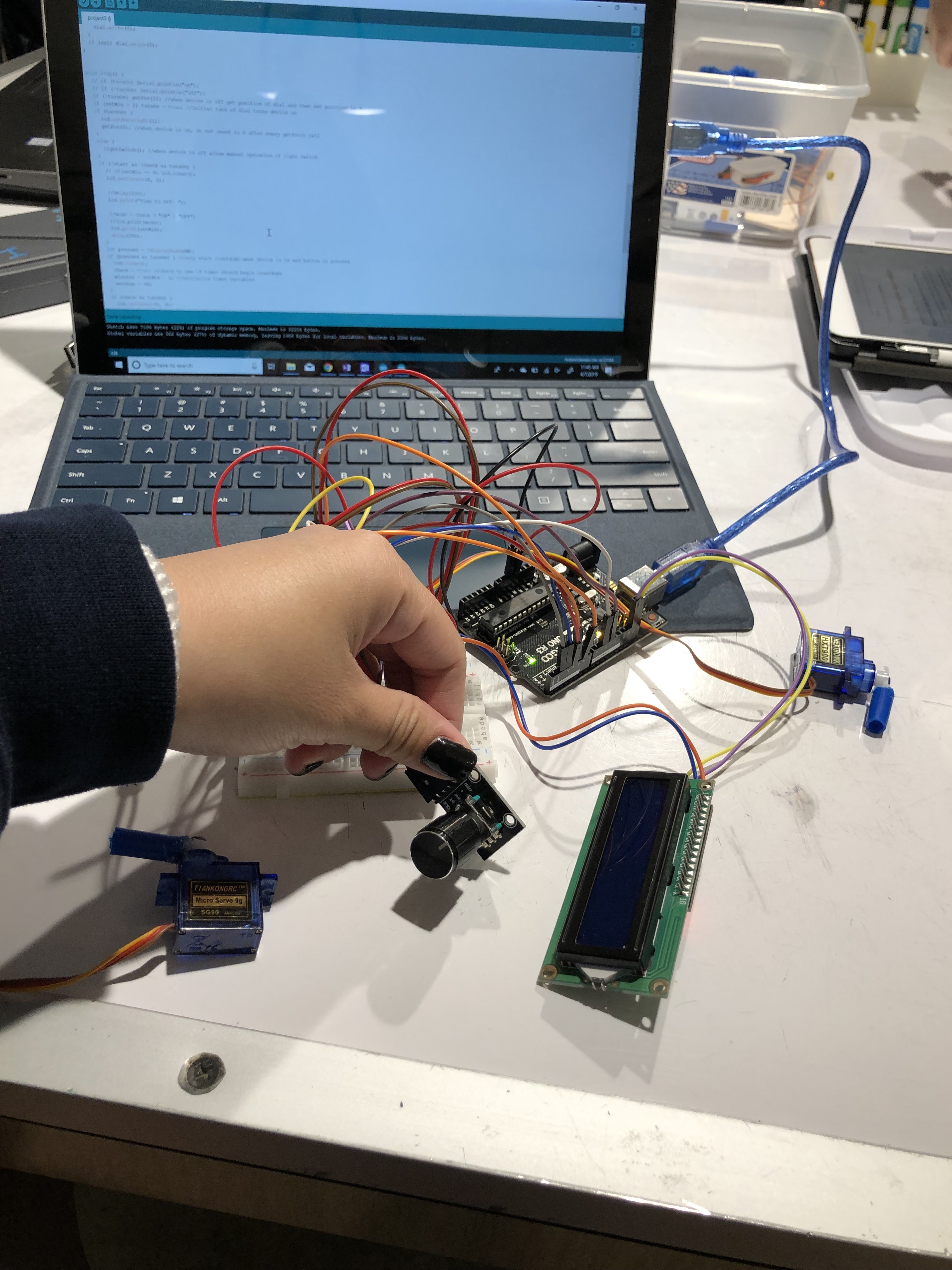
The display/UI elements only, with the code. We decided upon a knob for the timer and an LCD display to show the time.
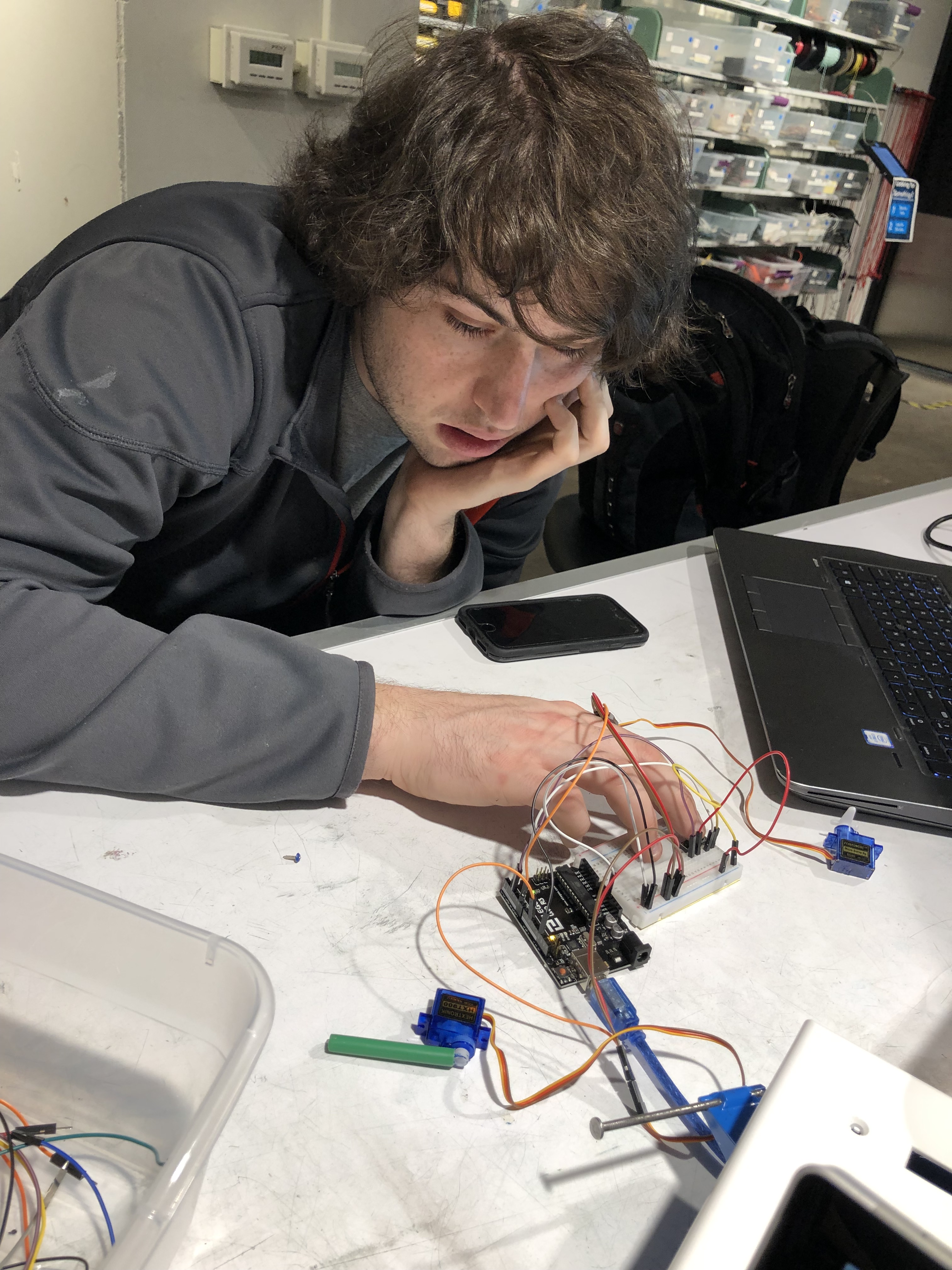
Fussing with the servos. There seemed to be a weird twitching with the servos at first.
The earliest mount prototype. We decided not to use this mount because we had difficulty fixing the servos onto it.
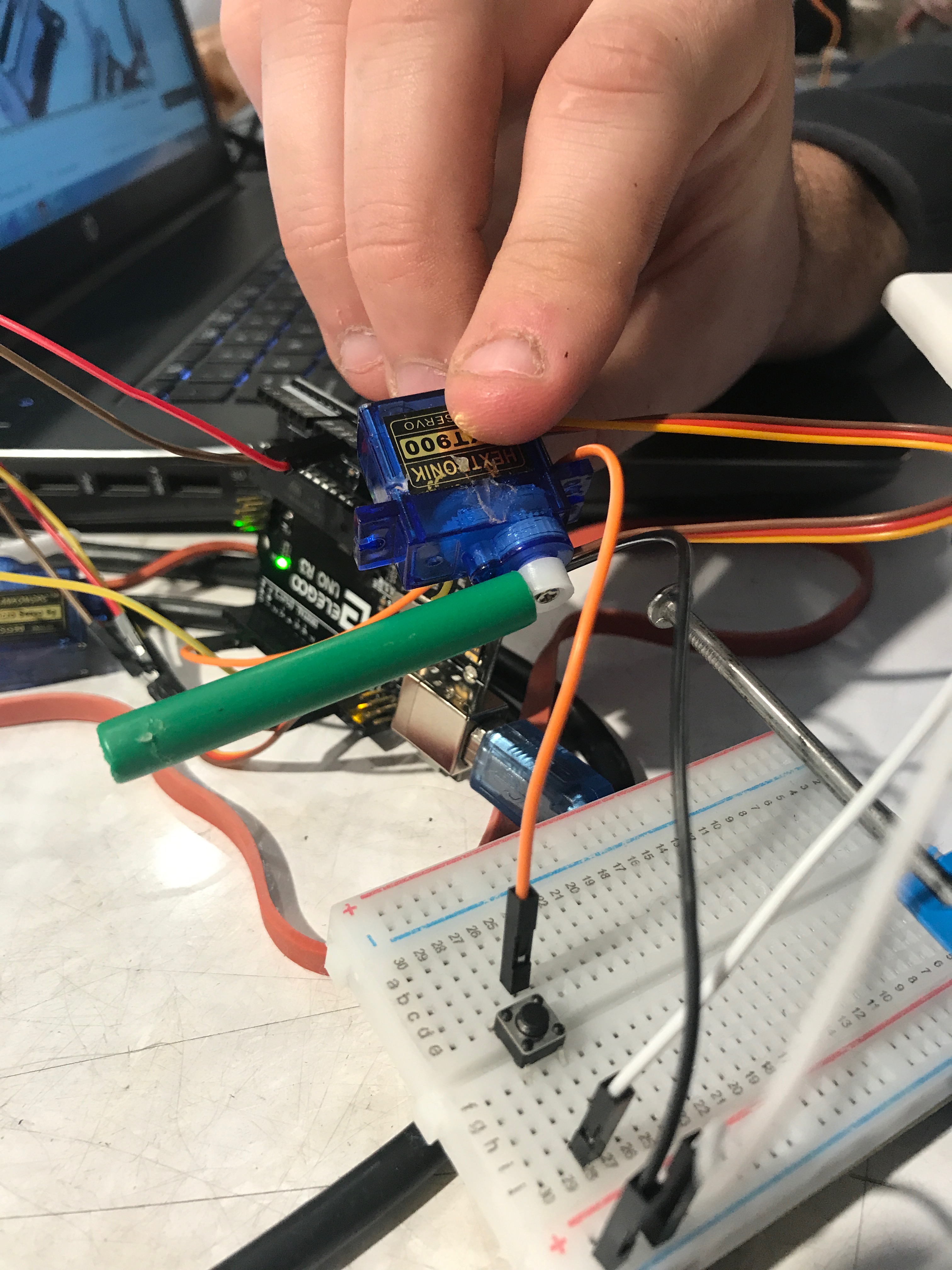
Extended servo arm for flipping the switch.
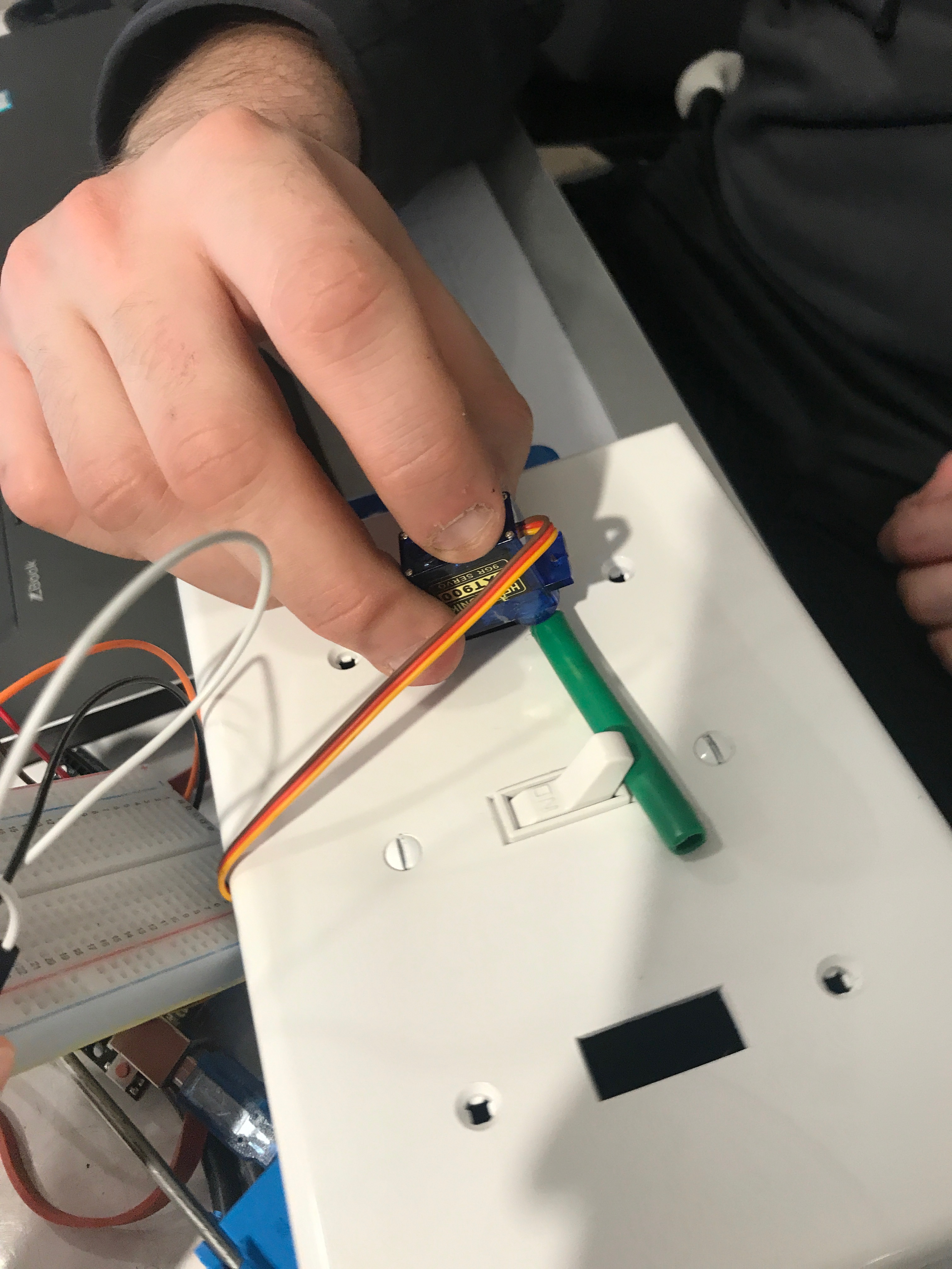
The servo arm with the switch. Here we are determining how long the to make the lever for it to be effective.
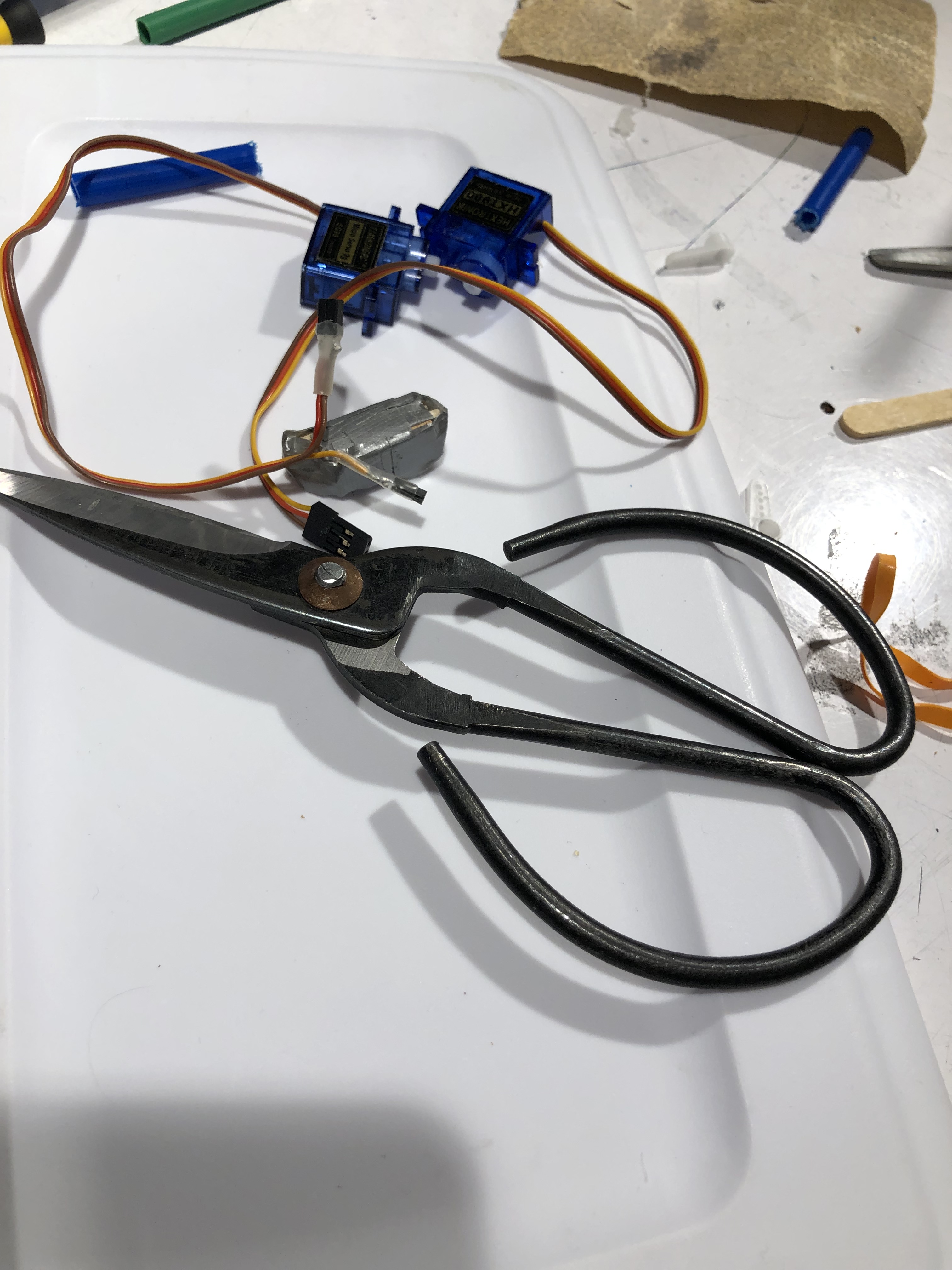
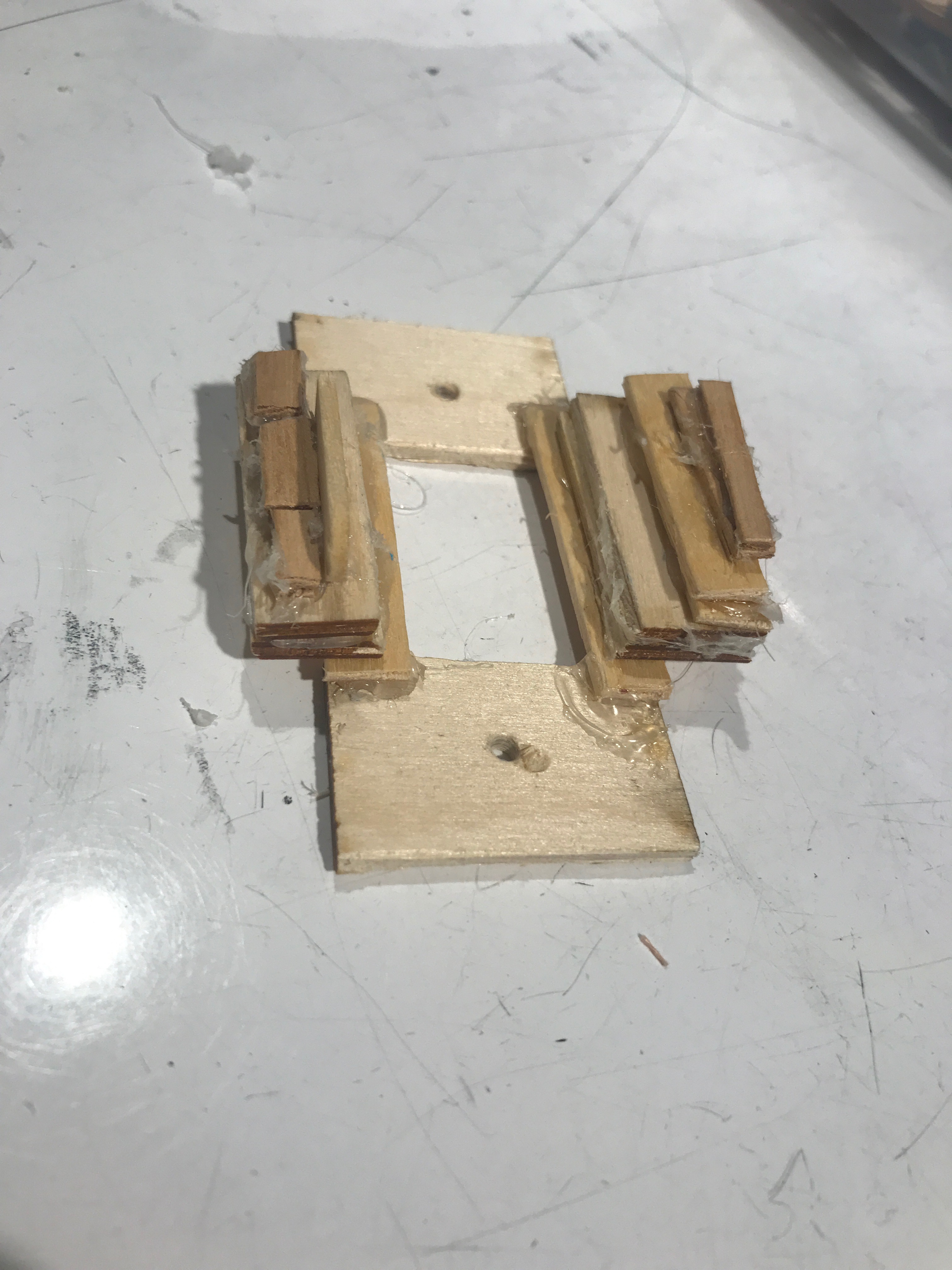
Starting work on the servo mount. Initial attempts were made with small pieces like the duct tape block shown above, which ultimately was ineffective.
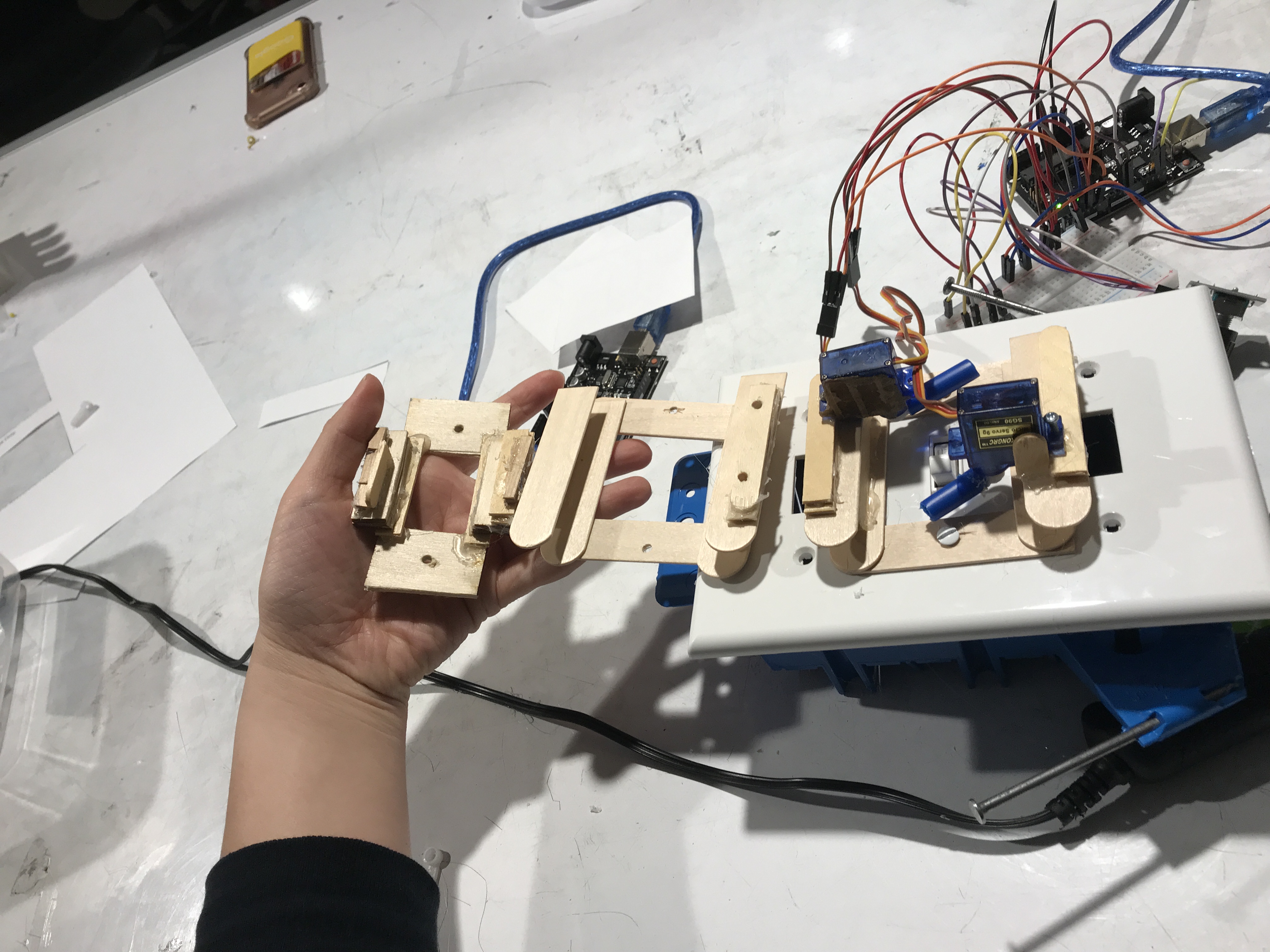
The progression of mount prototypes. The first just did not work at all. The second didn’t have the correct measurements. The final is a sturdier version of the second, with proper measurements.
Discussion
Unfortunately we did not have a feasible project idea until the Monday before the prototype was due; other teams were able to have a device idea days earlier than this. Consequently, we were unable to order the linear actuators we originally wanted to use to flip the switch. Mounting a servo on the light switch provided an interesting obstacle. We still wanted to allow the user to operate the light switch normally, so the servos could not obstruct the other switches on the light switch panel. The resulting prototype was a bit clunky, but it worked.
The critique ultimately reinforced some preexisting ideas of how we felt about the prototype. After having an in depth meeting with Kathy, we learned about some of her main concerns. Kathy explained that she wanted the device to be as neutral and unnoticeable as possible. She expressed a strong aversion at both the maximalism and homeliness of the prototype. Understandably, we reassured her that this was not going to be the final look of the product at all, as this was only the initial iteration. However, we could definitely make changes to our preexisting UI according to her feedback.
We included the LCD display and rotary encoder to allow for easy, straightforward operation of the device, but after receiving feedback regarding the redundancy of having so many moving parts, we agreed to scrapping them and replacing them with a simple potentiometer for setting the timer.
Going forward, we will address the visual design of the prototype, which we neglected in this initial meeting. We intend for a more polished mount that will either be machined out of metal or 3D printed. To allow this to blend in with the rest of the switches, the mount will be the same color as the wall plate for the switches. Kathy also mentioned that her current light switch plate is old, so we are probably going to buy a new plate that can accommodate 4 light switches, since this is the setup of Kathy’s switches, and then just swap the panels after the device is complete. Having this panel will make prototyping much easier and allow us to see what the final, installed device will look like without having to travel to Kathy’s home.
]]>Introduction
In the past two weeks, our team synthesized observations from our meeting with Irv to develop a “convenience machine” he could use to improve his daily life. From our insights, we decided to create a reminder device that’s unique to Irv’s unique and busy lifestyle (e.g., tennis meetings, gardening, cultural events). In this post, we’ve documented our thought process, experience with different components, and the reasoning behind the coding, electrical, and design choices we’ve made.
Interactive Itinerary Prototype
The Interactive Itinerary is a digital reminder system (think Google Calendar) that feels like an analog device. The user can set alarms for tasks or events without having to type on a tricky touchscreen. Instead, the user would write down the task on a piece of paper and set the alarm using built in knobs.
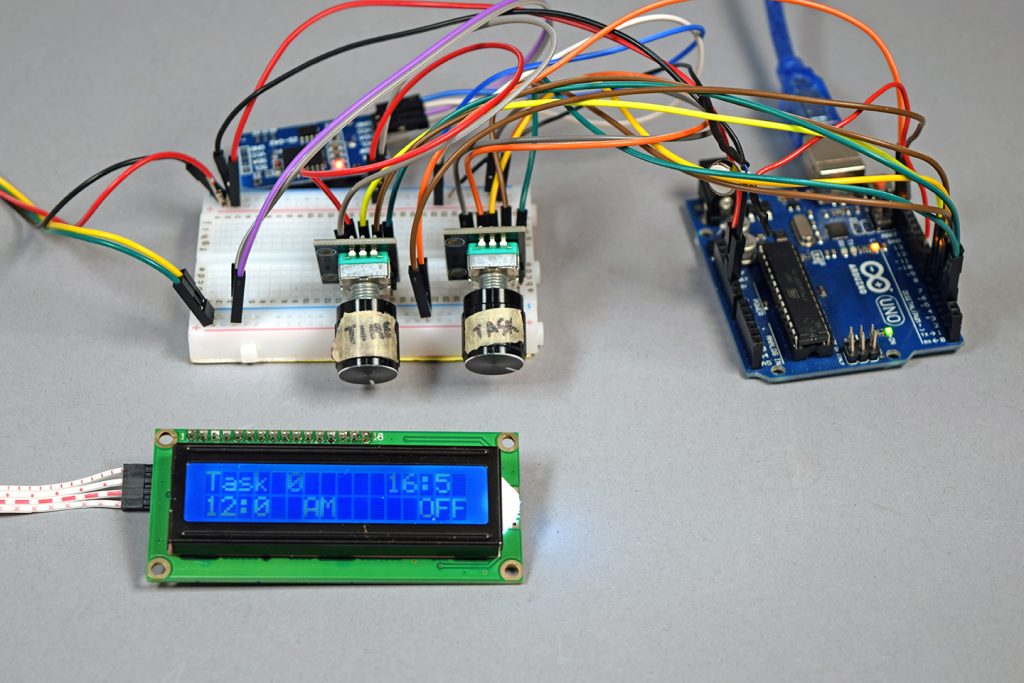
The time and task knob add to the analog inputs and the screen prints the desired outputs, such as current time, task number, andd alarm settings
The interactive itinerary prototype has 3 key components: 1) Two knobs that set the task and alarm 2) the digital display that shows task, time, and set time 3) a vibrating motor that acts as an alarm. To use the interactive itinerary, the user would write down a task on a piece of paper with an empty list from 1 – 10. Using the task knob, the user would turn to the desired task number turn the alarm on. Then, they would set the time using the time knob. When the alarm starts to buzz, the user can turn off the alarm with the task knob.
The LCD screen displays the current task that the task knob is on, the current time in the top right corner, the set time (hour:minute AM/PM) in the bottom left corner, and whether or not the alarm for the specific task is on or off.
The housing for the device was modelled after a notebook/notepad. This interactive notebook makes it easy to keep tasks that need to be completed by a certain time.
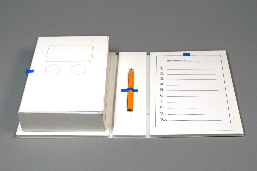
The mockup of the Interactive Itinerary housing is made out of foam core. The rectangle shows where the LCD screen would live. The two circles represent the task and time rotary encoders.
The electronics would live on the left side of the housing and the task list would live on the right side, making it easy for Irv, who is right-handed, to write down his daily tasks.
Process
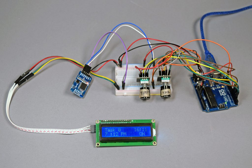
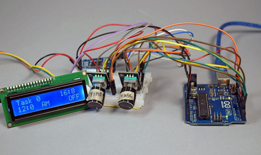
All the components of the prototype hooked up and ready to go
After meeting with Irv, we decided to move forward with the task reminder device that is more of a physical alarm, as opposed to a audible or visual alarm. Our team started by making a list of goals and potential features for the device.
After making a list of problems Irv mentioned, we branched off each idea to find ways to help Irv. The ideation tree helped us deterine basic goals for the design and feel of the device for Irv
Alarm Notification
Because Irv’s hearing is not great and because purely visual alarms are not noticeable when put away, our team chose a vibrating notification system. The micro vibration motor is very small but strong and noticeable, making it the perfect fit for this device. As shown in the picture below, we secured the soldering with heat shrink to keep the vibration motor attached.
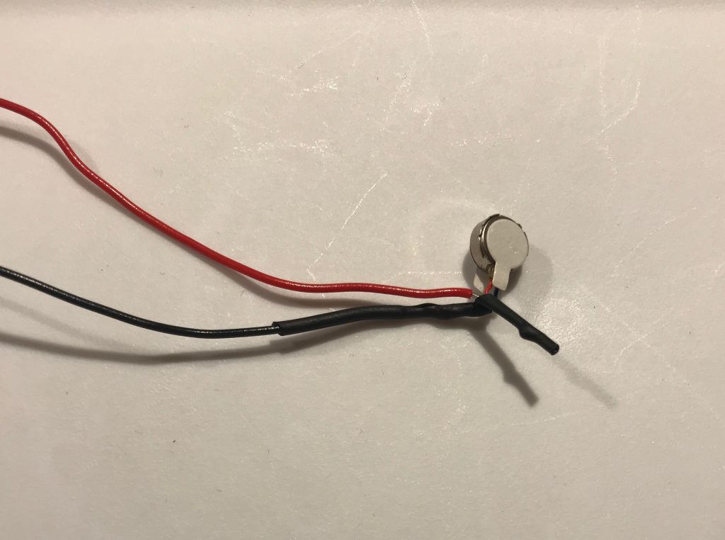
Heat shrink to secure soldered wires to the micro vibration motor because when it vibrates too much, the soldered wires fall apart.
Real Time Clock
Setting up the real time clock was relatively simple. We used a built-in example from the RTC library to set the time on the RTC. To get the time from the RTC and use it as an alarm, we used a built-in function from the Time.lib library called setSyncProvider(RTC.get).
When we initially ran the code without this line, the alarm did not work. WIth this line, we can also easily display the current time. After putting this in void setup(), we can use functions like hour() or minute() to collect the current hour and time data from the RTC.
Since the time on the RTC runs on military time and we wanted to display the time with AM and PM, we had adjust the logic of the alarm setting. We ran into trouble when we were trying to compare the PM times to the 24-hour time because the numbers do not match up. In this section of the code, we are storing an alarm hour for a specific task into an array title alarmHour. By modding the timeButtonCount by 5, we can get 5 states to condition over.
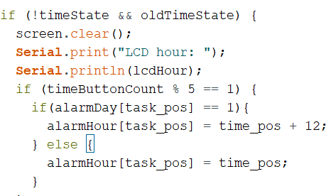
This section says that if we are setting the hour for a PM event, we will add 12 to the alarmHour for that specific task so that it matches the 24-hour time.
Rotary encoders
Since Irv is not comfortable using the touchscreen on his iPhone, we aimed to make the device as intuitive and analog as possible. The rotary encoders we used have 20 detents which provides a good tactile indication for the user. It also has built in push button that acts as a “confirmation” button for the time button. For the task button, the push button turns the alarm on or off.
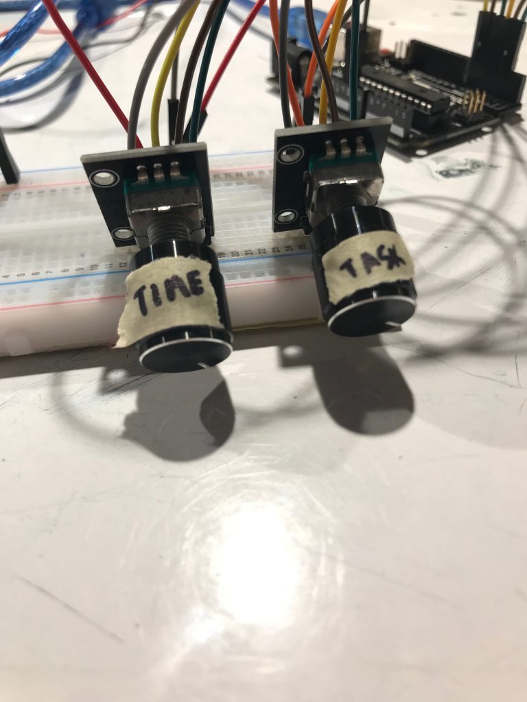
The task rotary encoder cycles from 1 to 10 as the user rotates the knob. The time rotary encoder cycles from 1 to 12 on the hour state, 0 to 59 in the minute state, and AM or PM in the time of day state.
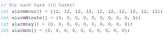
To keep each task alarm independent from other task, the alarm hour, minute, time of say, and on/off states are stored in matrices. Each matrix has 10 elements for the 10 tasks.
The alarm on/off button was initially dependent on the task position beause it was inside that if statement. To keep everything independent from one another, we kept each part of the device separate. So the time knob, time button, task knob, and task button are all in separate conditionals.
LCD Display
Our group wanted to use a Nokia 5510 graphic LCD 48 rows x 84 display because it had a better finish and display that the large blue LCD display. This graphic LCD proved to be a large challenge, partially because there is little documentation on the screen. The Nokia 5510 would involve bitmapping, which is something the group was unfamiliar with. After hooking up the Nokia 5510, and uploading a sample we found online, the screen remained blank but the LEDs in the back lit up. After troubleshooting for a while and a couple dead ends, we decided to transition to blue LCD and return to the Nokia 5510 at a later time.
The Nokia 5510 has a small an clean interface that requires bitmapping. The Nokia display is preferred over the blue LCD.
Discussion
Our prototype was overall functional for the crit on April 8th. We demonstrates the buzzing alarm function to Irv and taught him how to set the task and time on the device. However, before the presentation, when our group powered the device using a 9 volt battery, the RTC reset it’s clock to 0:00. We managed to reset the current time on the RTC and reupload the code onto the device. However, we were only able to run the device on a laptop.
We received many helpful comments and feedback from the Osher group, Irv, and people in this course. One idea our team, including Irv, really liked was the snooze button because it is a function that will most definitely come in handy for Irv. After consulting Irv, we planned to add a snooze button that specifically snoozes for 15 minutes after the alarm. We also pulled out several different switches and buttons for Irv to try out to see which part felt best for him. Zach also suggested adding a cursor to the LCD display and reminded us to fix the current time display on the LCD screen so that the time reads in the 00:00 format. This change will make it less confusing for Irv and more uniform.
After the crit, the team, including Irv, decided set some goals for the final design of the Interactive Itinerary, We want to make the device as small and thin as possible so that it could ideally fit in Irv’s back pocket. This also means that the material should be flexible enough to maintain its structure when there is pressure applied to it. To make the Interactive Itinerary smaller, we would have to explore ways to rearrange the rotary encoders, which are relatively thick. So, we plan on exploring flexible but sturdy materials that can withstand a certain amount of stress as well.
Moving forward, our team plans on adding features and improvements to our existing prototype. In addition to the snooze button, cursor, and the time display, we also plan to display the task number when its alarm goes off. Since Irv prefers to set the time using military time, we will be taking out the AM/PM time format. We will have to figure out how to position the knobs to minimize the thickness. We want to troubleshoot how to power the device with a rechargeable battery without it resetting the RTC. While the LCD screen is easy to use and completely functional for our use, we still want to revisit the nokia screen and see if we can get it to work. Lastly, we would want to add a blue feature to the device because that is Irv’s favorite color.
]]>
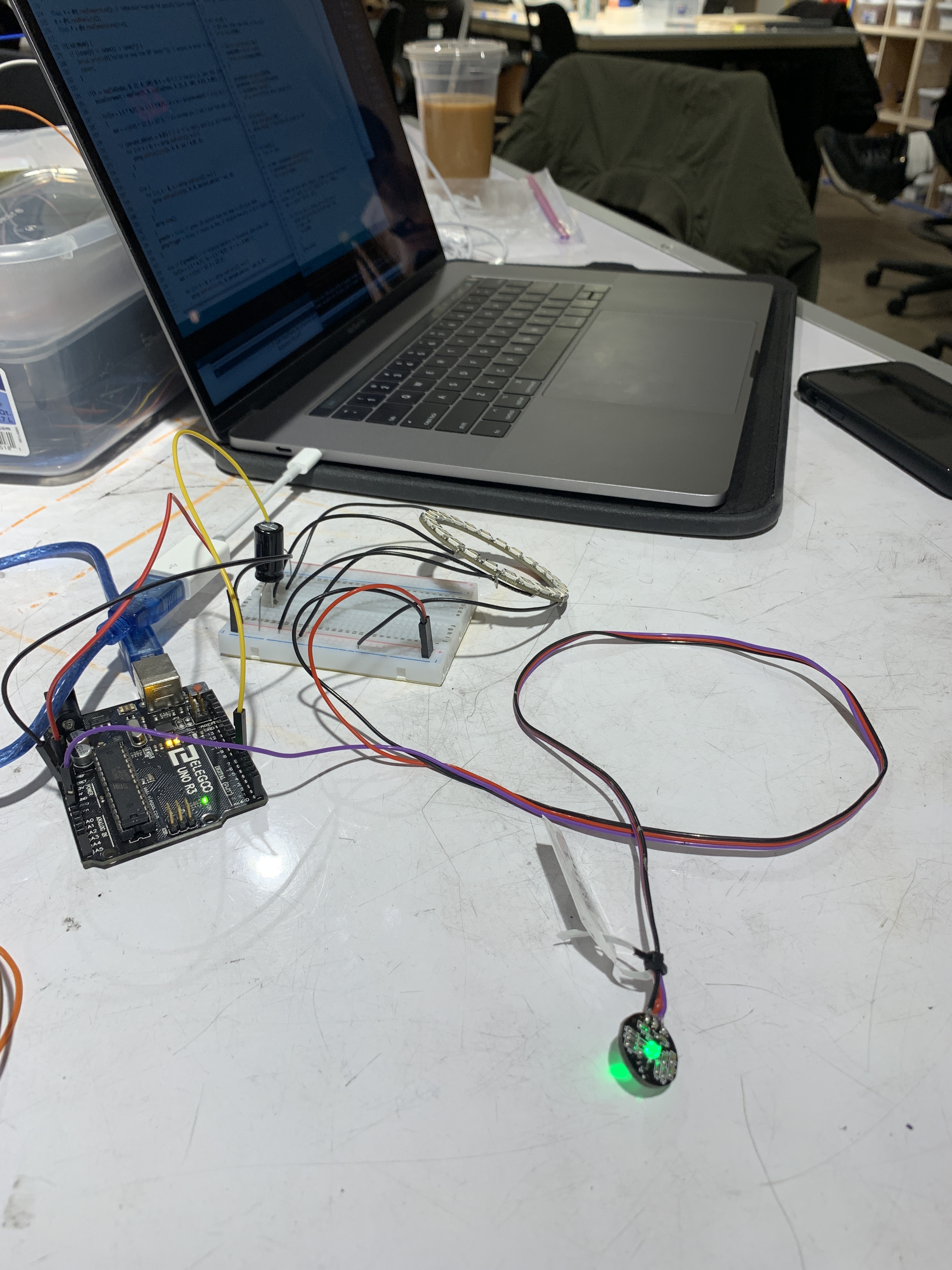
After meeting with Elinor, we decided that we wanted to make her a device that helps her focus on her mindfulness and encourage her to take some breaks during her busy schedule. The prototype that we built synchronises heart rate monitor readings with an LED ring and a vibrating motor to help Elinor visualise her current state and bring her back down to her resting heart rate.
PROTOTYPE
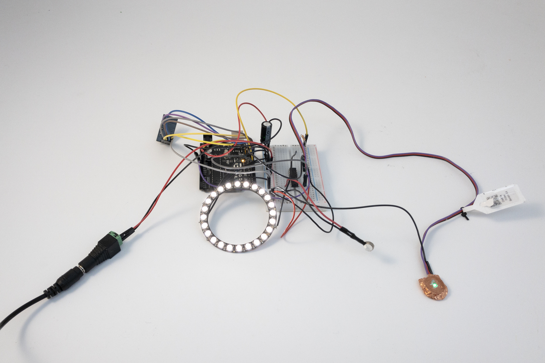
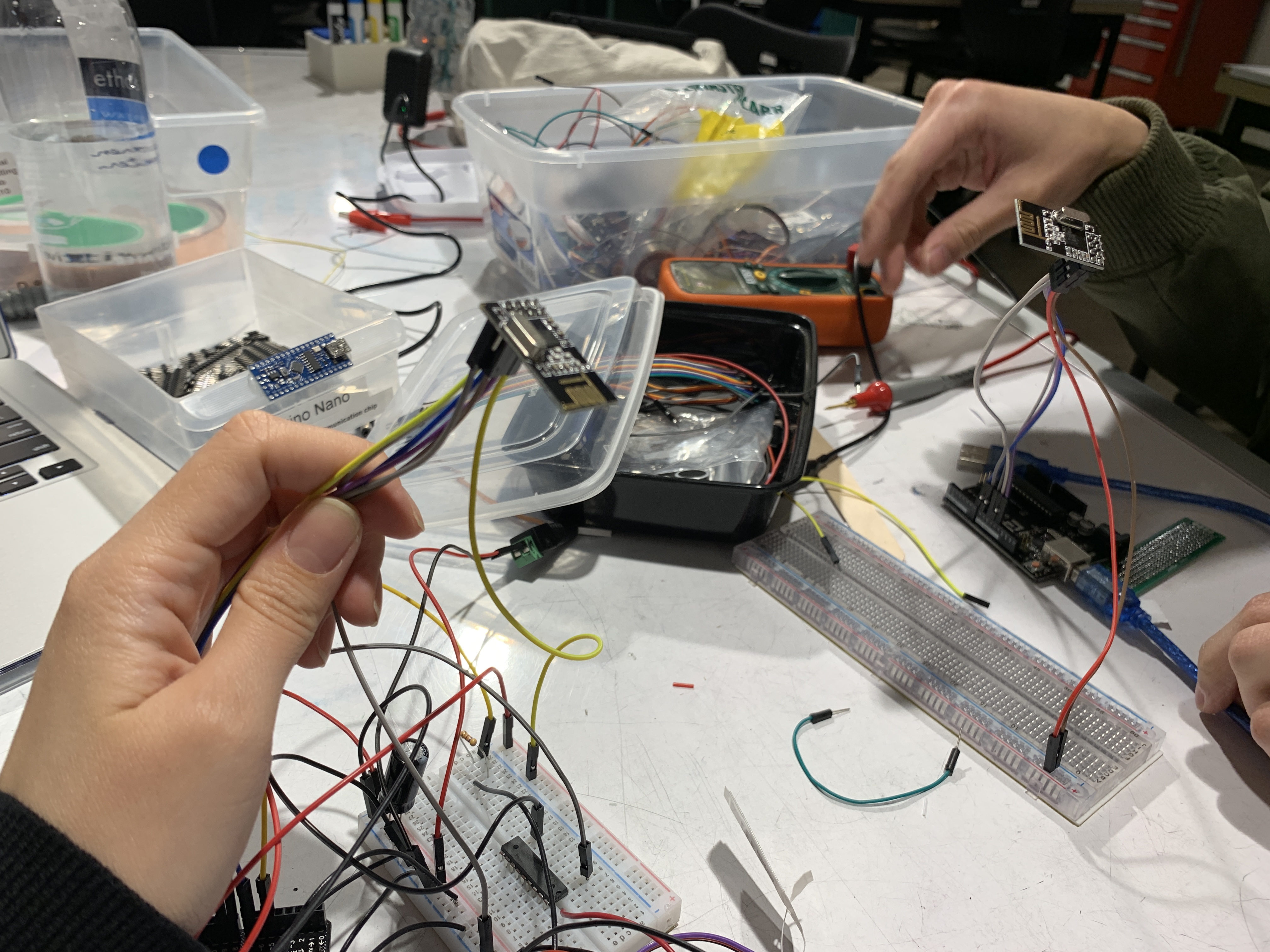
The development/testing setup with components plugged in to a breadboard. Included are a pulse oximeter, vibration motor, LED ring, and wireless communication module.
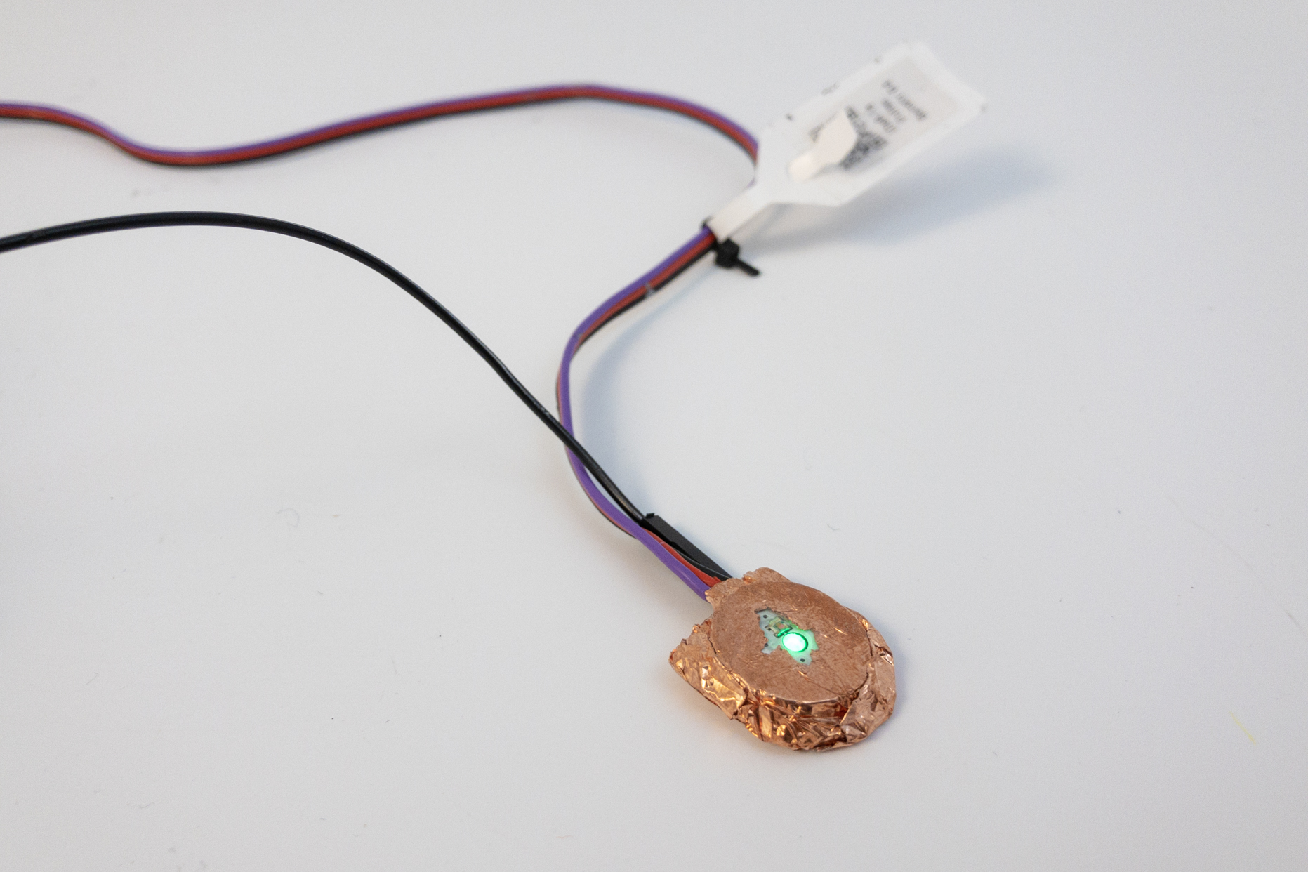
The pulse oximeter (called a “Pulse Sensor Amped”) exhibited large amounts of interference, particularly around moving metal objects. We tried creating a Faraday cage around the part to shield it from such effects, but success was limited.
PROCESS
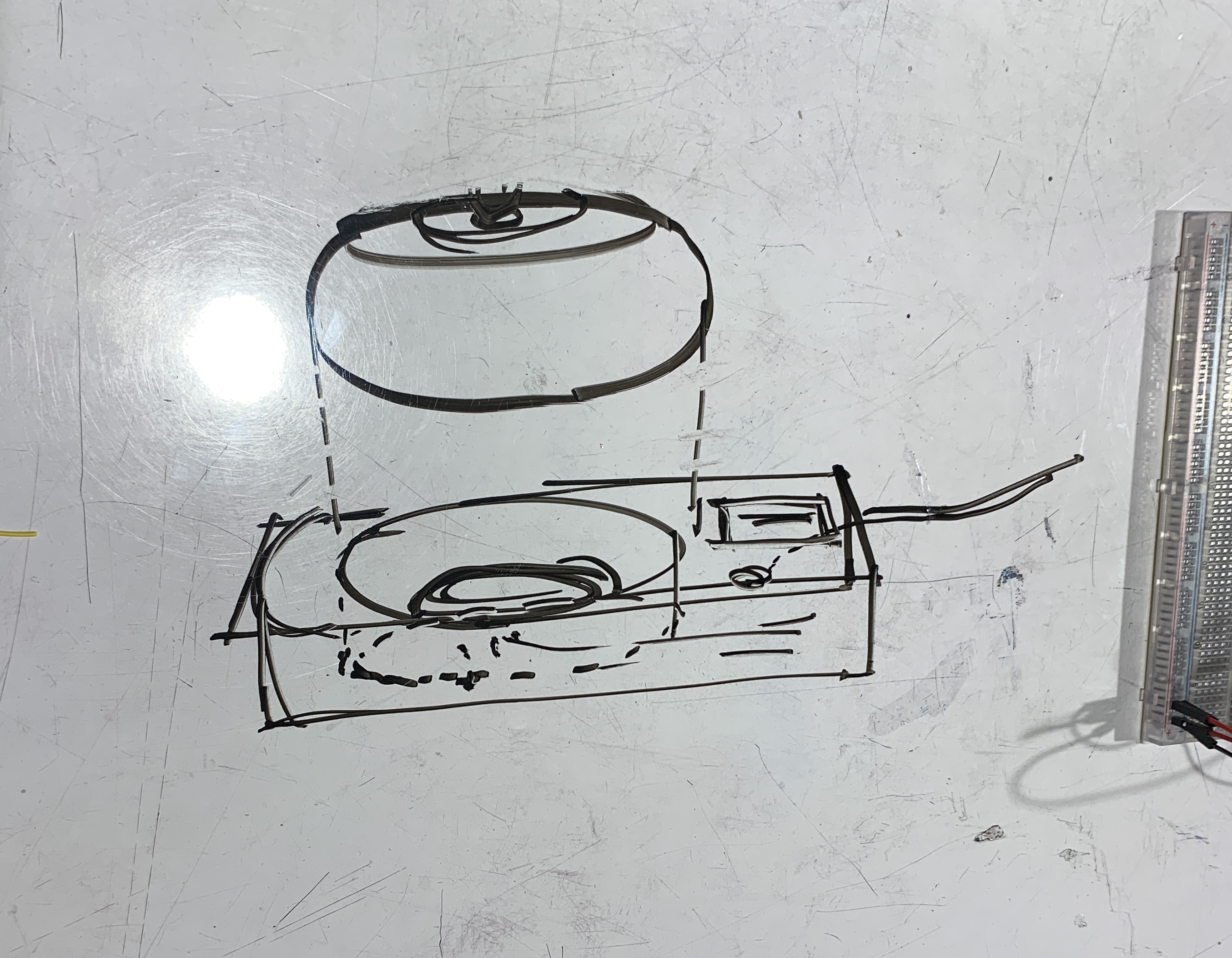
A sketch of how we envision our device: a portable pebble-like device EIinor can take on the go, that has a dock where she can charge it and see historical data related to her heart rates.
The first electronics part we tackled was the heart rate monitor and synchronising the readings with the LED ring.
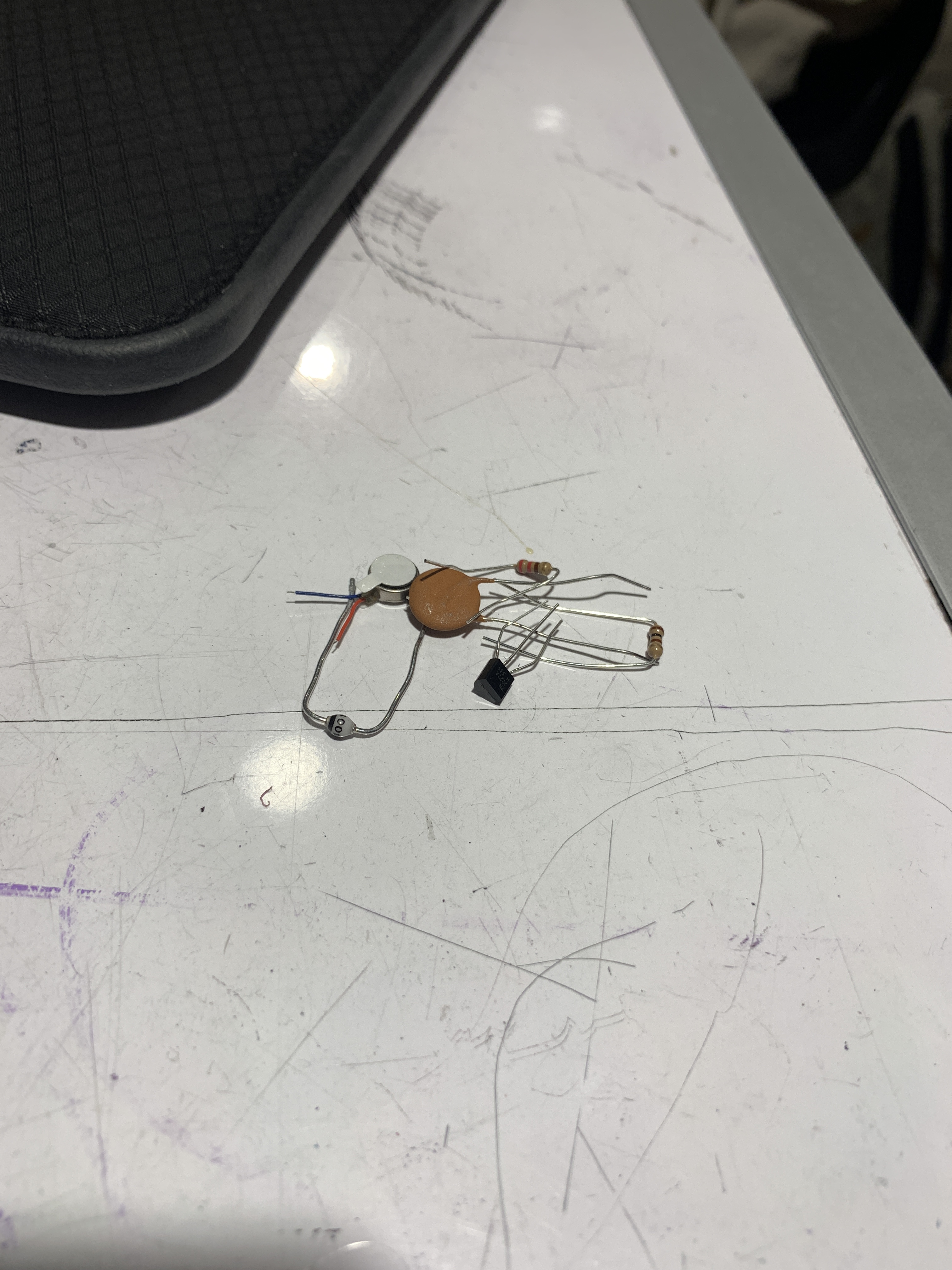
We were originally using all of these parts to wire our vibrating motor, but we learned soon after that we could just use a ULN2803 transistor instead.
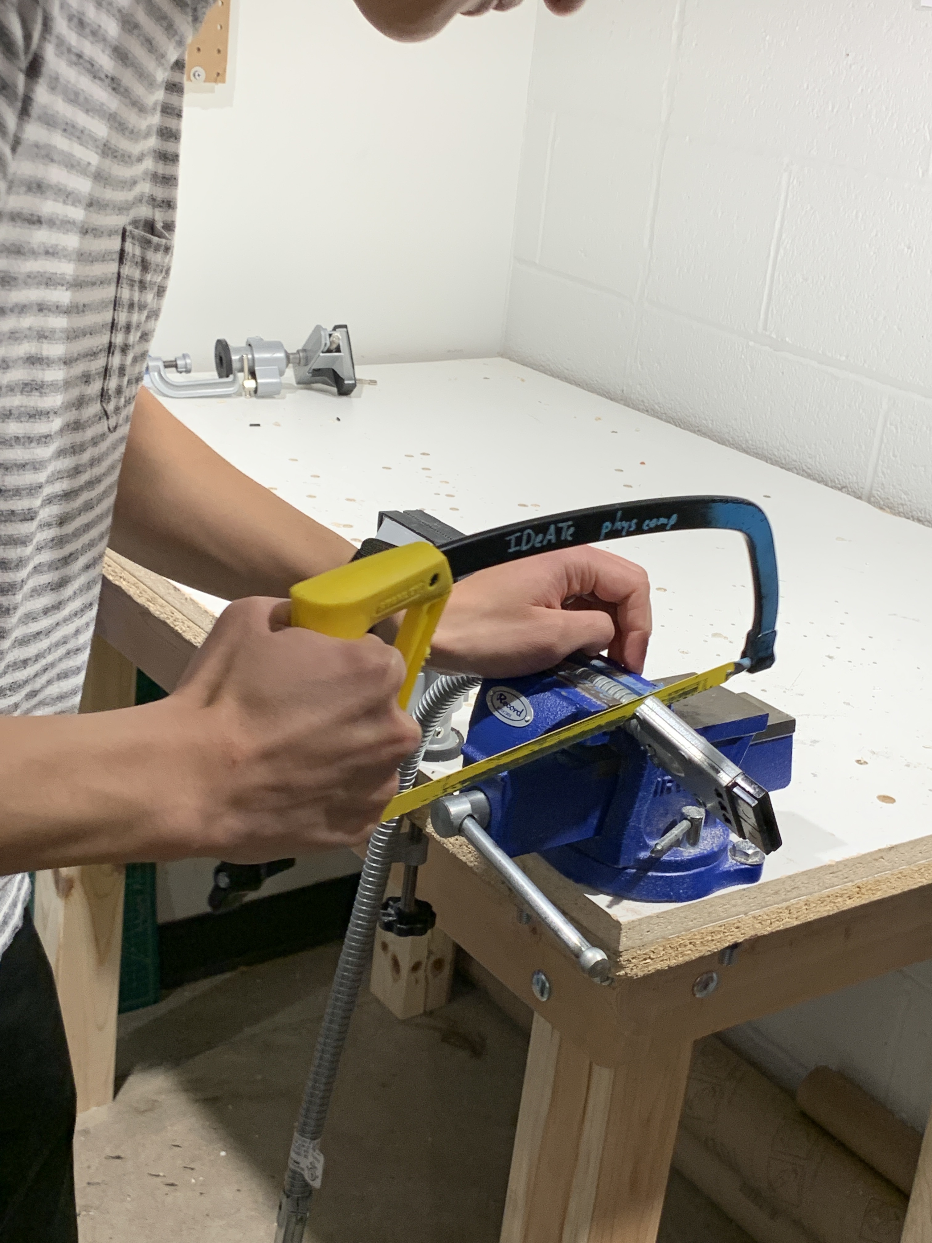
Ian is working with a metal tube that we intended to use over our heart rate monitor because we were running into weird issues with interference from nearby metal objects.
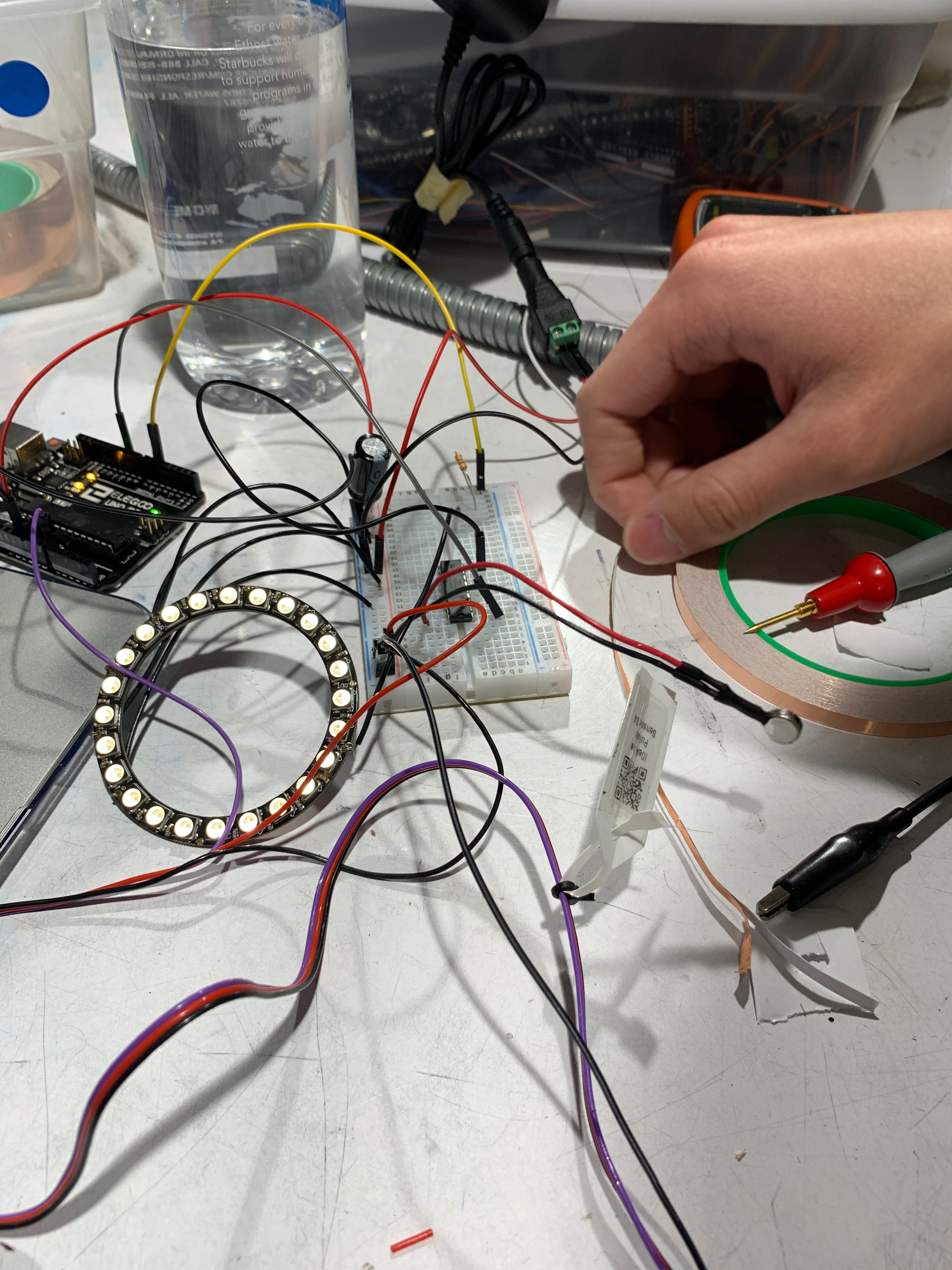
After adding all our basic components (LED ring, heart rate sensor, vibrating motor) it was kind of crazy and we were working to make things as organised as possible, but we were nearing the end of our prototype building.
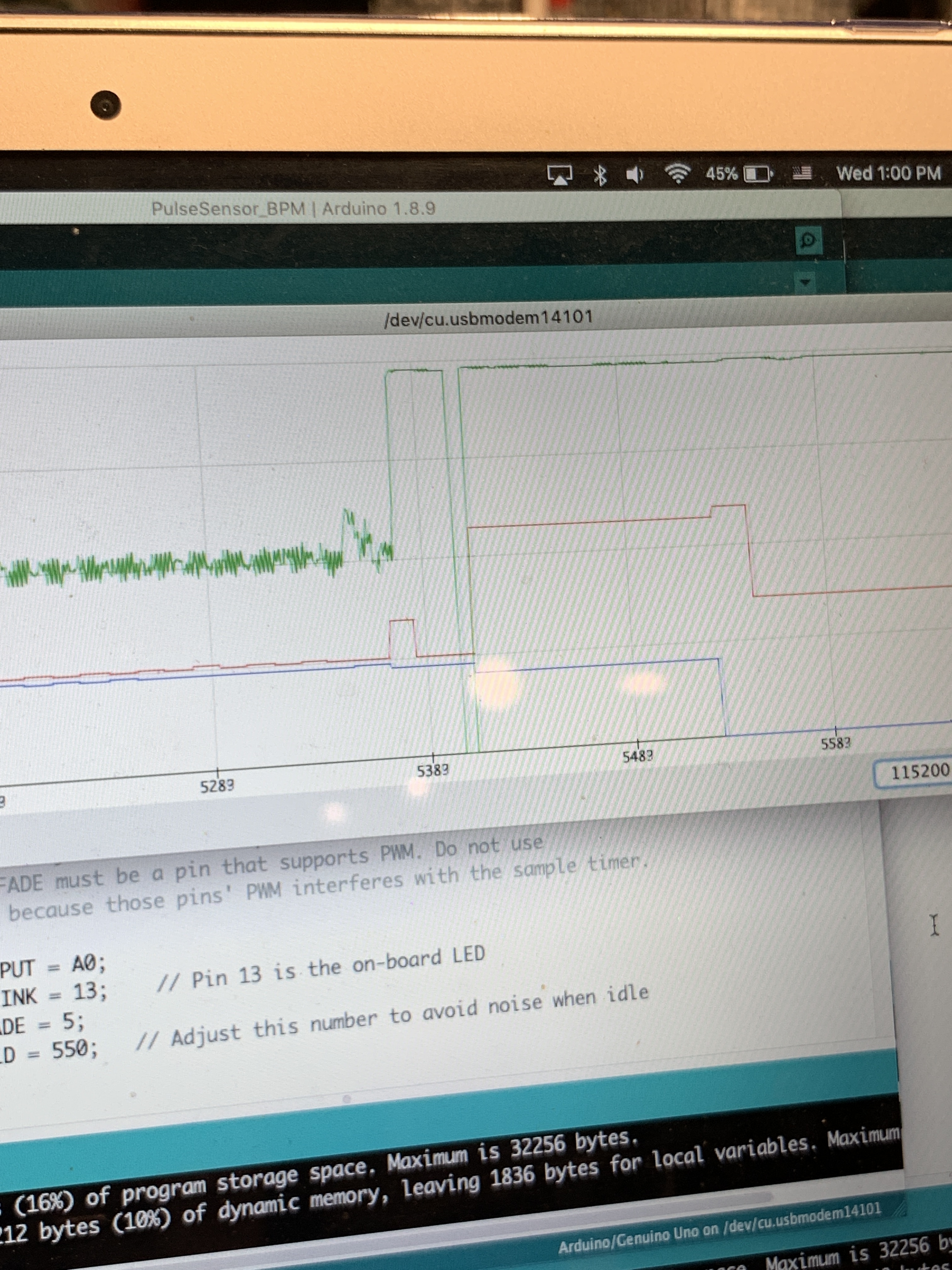
Here (the red line is the heart rate monitor) are some example readings we were getting, where the sudden spikes and dips are due to waving metal objects over the heart rate monitor.
Another feature we worked on was remote data transmission and receiving between 2 Arduinos, so that Elinor can receive data from her portable device on her dock.
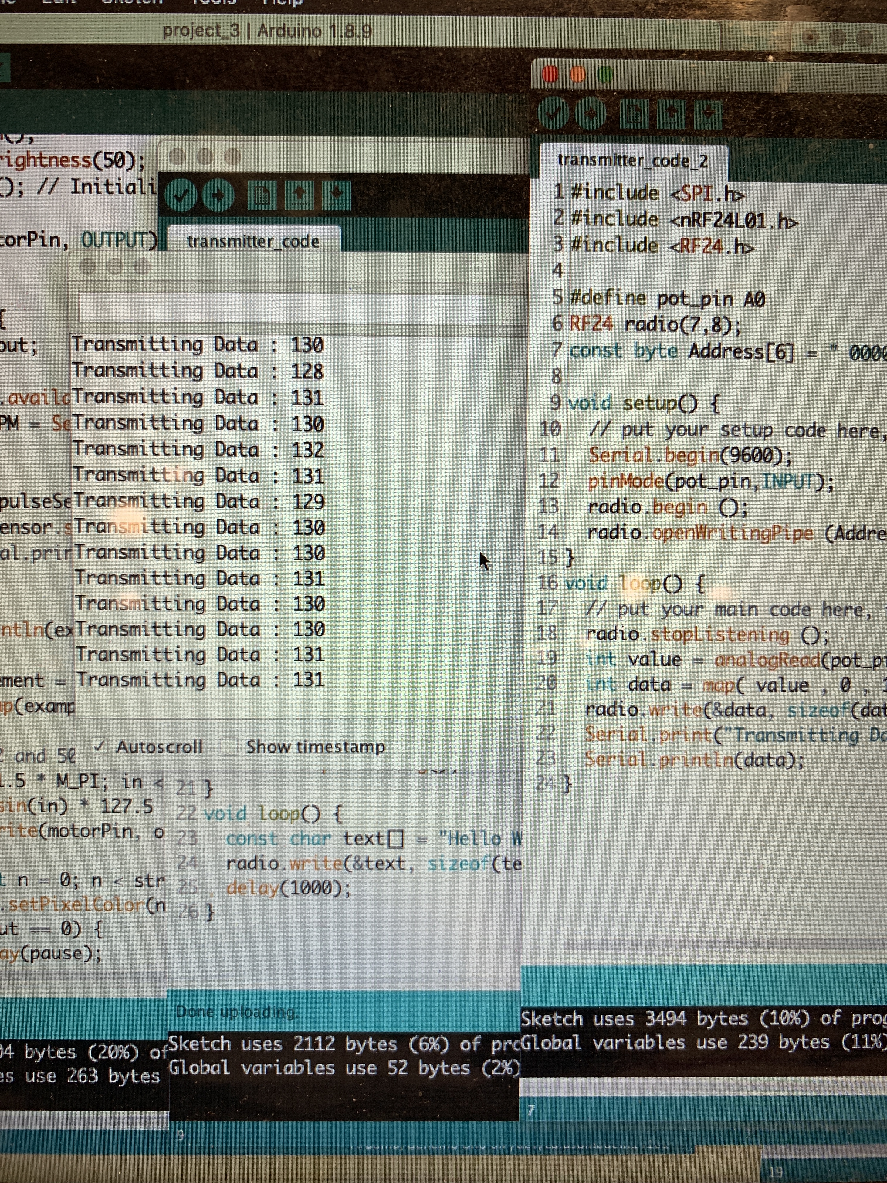
The code for the transmission side of the data transmission/receiving. It took a couple of tries but it ended up working!
Preliminary renders
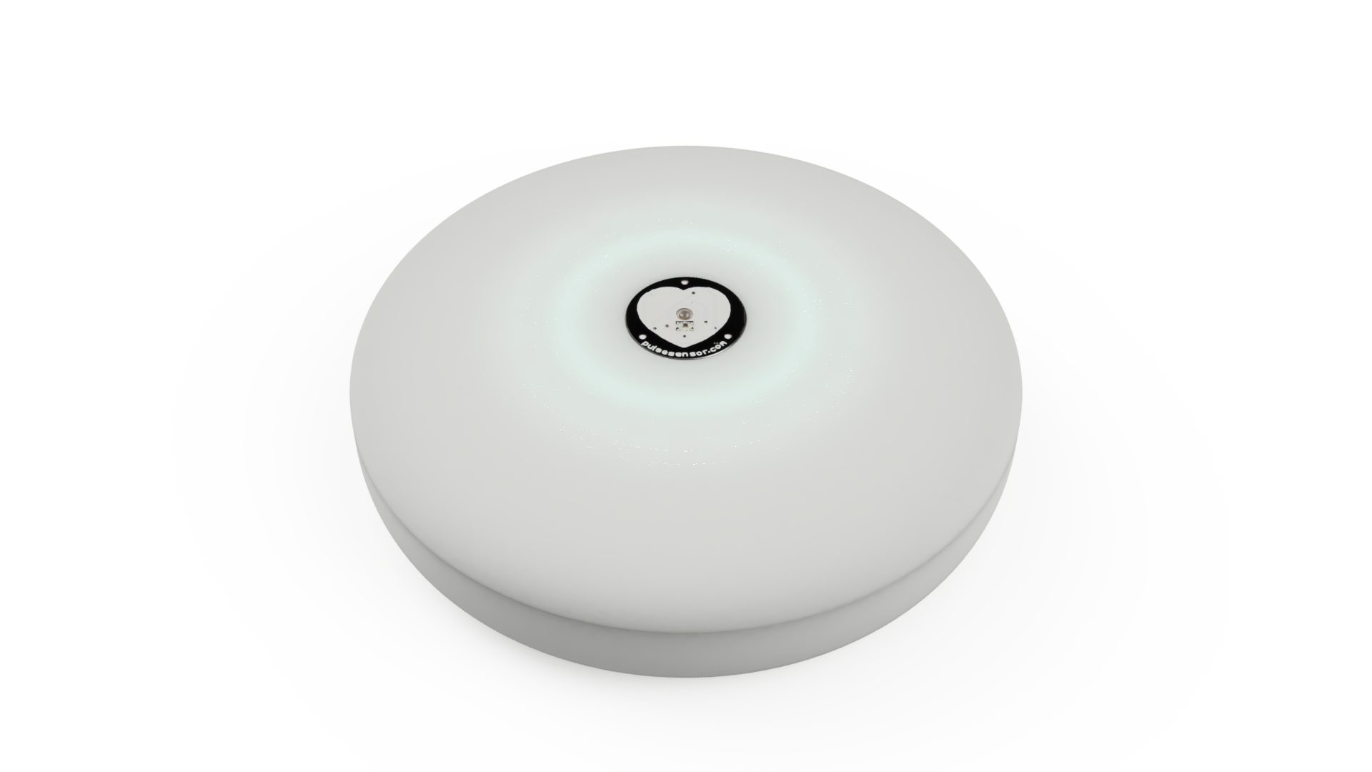
A concept for what the mindfulness device could look like. The LED ring is embedded beneath the surface and diffuses through translucent material.
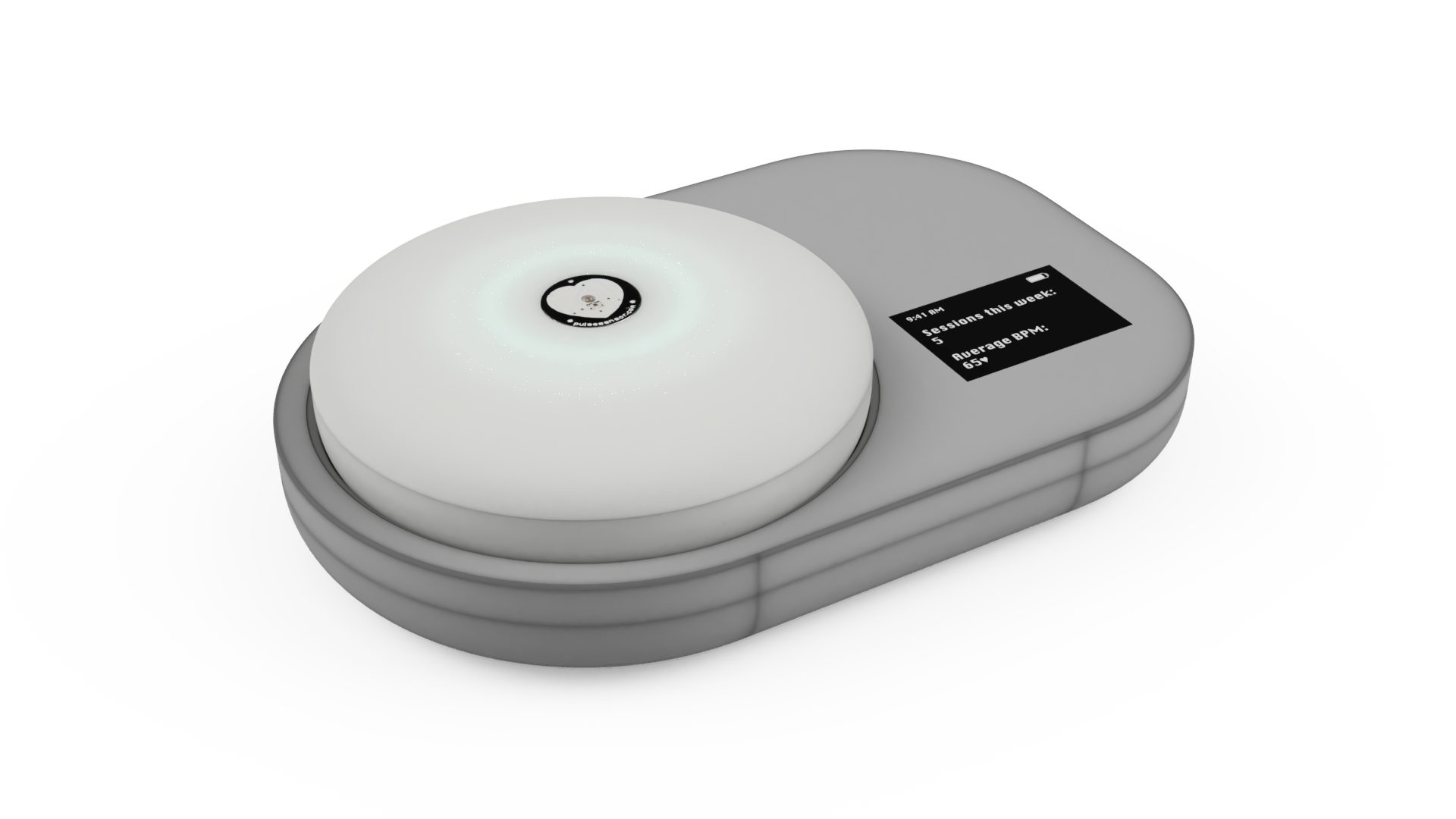
At the end of a day, the “pebble” can be set in its dock to charge and sync data.
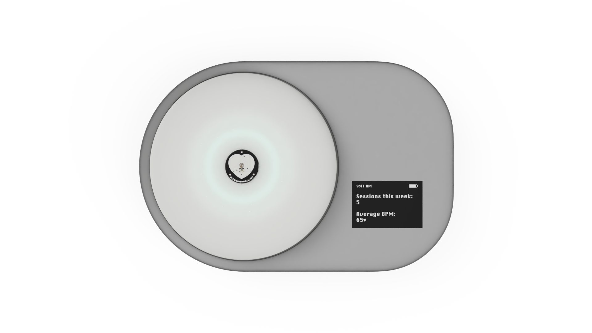
An LCD on the dock provides insights and trends regarding number of sessions a week and heart rate trends.
DISCUSSION
When we first started working on our prototype, we mainly ran into some major issues with the heart rate sensor. On the first couple of days we worked with the part, readings were really stable and showed a lot of promise for our prototype, but some days that we went into the lab to work on it– the sensor would show odd readings that weren’t actually corresponding to our heart rate when we also used other devices like a smartwatch. After testing different theories, we found out that waving metal objects like our phones was causing the readings to spike and dip weirdly. We tried working with a code and adding in some smoothing functions as well as some hardware solutions like covering the part with a metal tube, and ended up wrapping most of the sensor in copper to mitigate the interference of nearby metal objects. For our prototype demo, we inserted code so that BPM can be entered and different speeds of haptic feedback and LED patterns can be visualised.
Some other challenges were related to synchronising the heart rate monitor with both the LED ring and vibrating motor. We wanted both parts to “pulse” in correspondence with the heart rate detected, so that a higher heart rate would map to a faster pulsing and similarly for a slower heart rate. Figuring out the right speed for this pulse took some trial and error and some running up flights of stairs to test for elevated heart rates, but we were able to add in a function that both of us were satisfied with.
The crit on April 8, especially our consultation with Elinor, was really helpful in gauging how Elinor felt about the device at its current state and what she wanted to change about it. She had several ideas for us related to adding in more functionality specifically related to mindfulness, the ergonomic factor of the device shape and sensor placement, and the pulsing component. Elinor was concerned that the device would only act as a heart rate monitor, and suggested adding in some voice control or voice recording playback that plays guided messages of meditative exercises. It was useful to know this information and definitely got us thinking about how we might add in some more functionality without losing the simplicity of the device, since we wanted this to also act as a sort of tactile device that Elinor can physically interact with.
After seeing our renderings, Elinor also mentioned that the placement of the heart rate sensor (on the top surface, right in the middle) could hinder her from being as relaxed as possible, since it isn’t a natural grip for her. The placement of the sensor could possibly be changed from the top to the side of the device so that it reads her heart rate while she holds the pebble in her hand without needing to consciously move her finger to the center.
Next steps
Moving forward, we definitely want to keep Elinor’s considerations at the forefront and work on adding in more functionality that guides her through some relaxation exercises. Due to technical limitations we are unsure if we will be able to implement interactive voice features or voice control, but working on a voice/sound related feature is something to focus on. We are also thinking about creating playlists of calming and meditative music that Elinor can listen to as a supplement to her usage of our device, or a similar solution. After adding some more functionality and finishing up the portable device, we are going to work on the dock and its related features such as charging and data aggregation. The fabrication of the device itself is also really important to us and we want to make sure to have enough time to create a relaxing-looking and feeling device (likely 3D printed).
Additional modes have to also be implemented. Examples would be the lighting/haptic sequence signaling to get ready for a session and different patterns at the end of a session: a sequence to indicate a good session and another to indicate that another session may be in order. Synchronization also has to be hashed out (what the LCD interface looks like, what data is displayed on it, how charging and synchronization works on the backend and human-facing, etc.) Although most major components have been connected to the Arduino with basic functionality, the greatest challenges lie ahead: implementing all necessary features elegantly and effectively and combining electrical components with the physical enclosures.
]]>Previously, we interviewed Peter about his typical day-to-day life and hobbies in order to get a better understanding of his interests and personality. Ultimately, his strong curiosity regarding the wind speed on his porch is what propelled us into our proposed solution for him: a personalized anemometer that would relay information relevant to his needs. An overview of this documentation is as follows:
- Prototype images + brief animation
- Major Challenges (Aesthetics and Functionality)
- Critique and Review from meeting again with Peter
- Next Steps
More about the initial interview and brainstorming can be found here: https://courses.ideate.cmu.edu/60-223/s2019/work/interviewing-peter/
Prototype
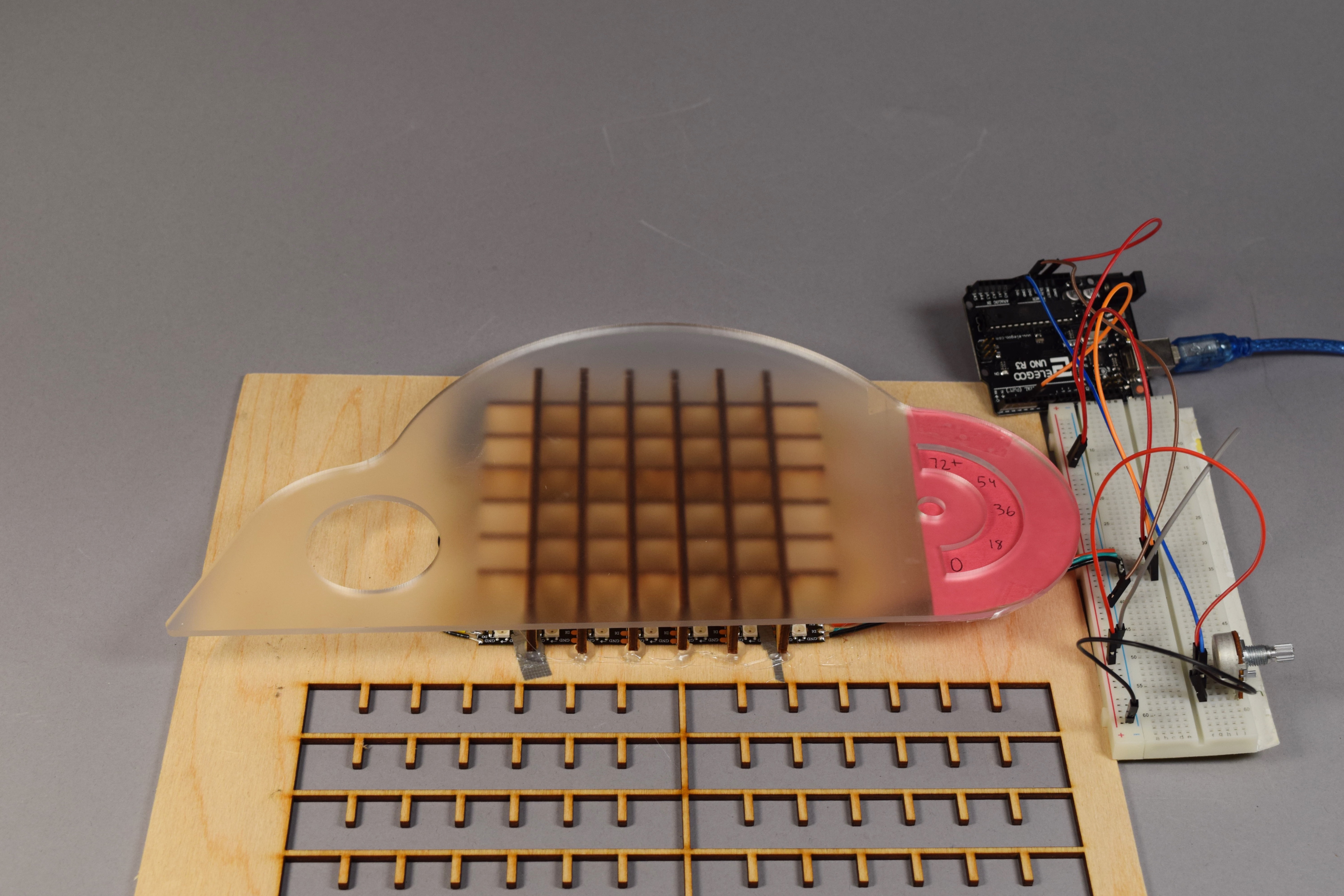
Cloud Prototype Process 1
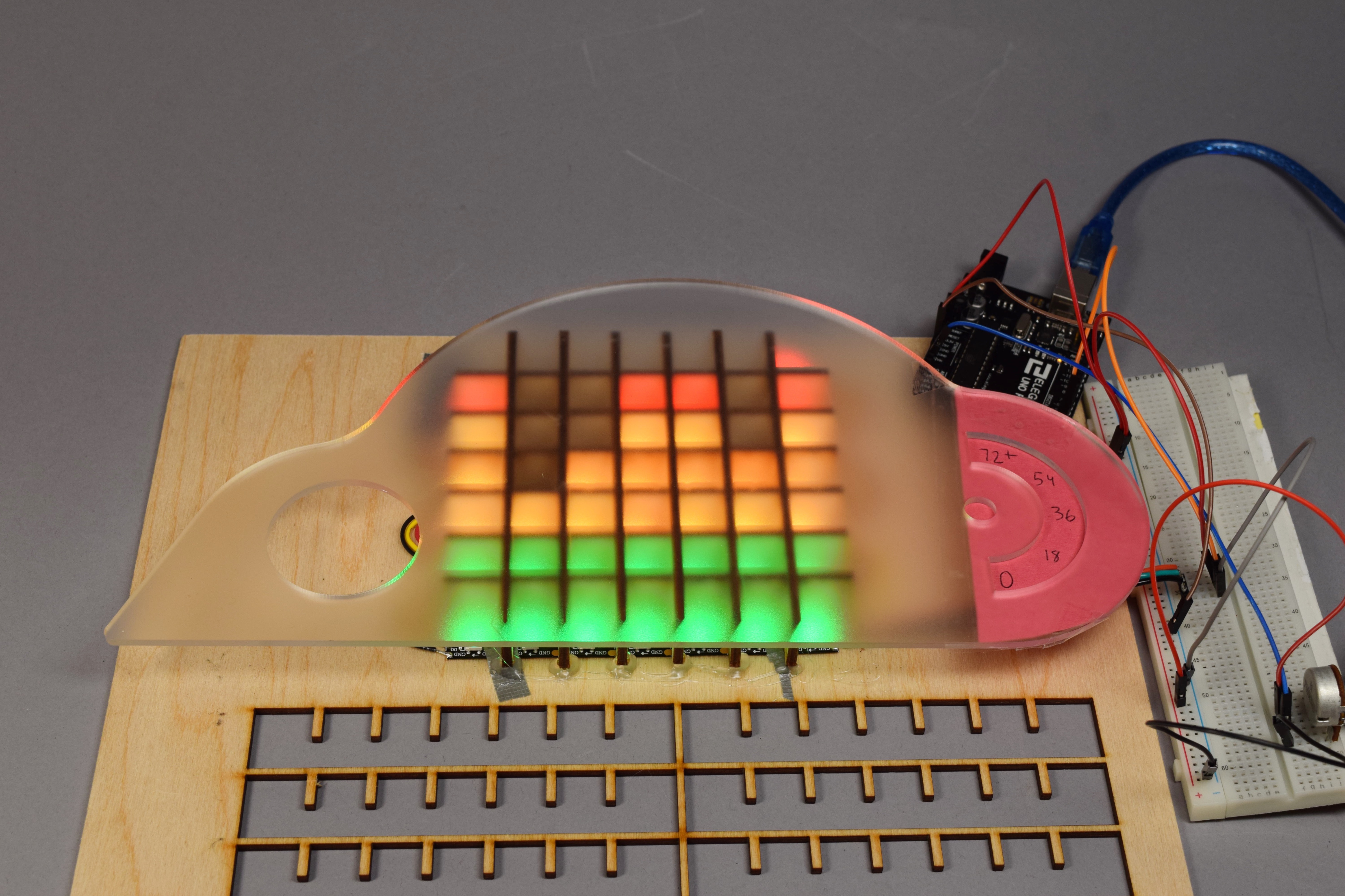
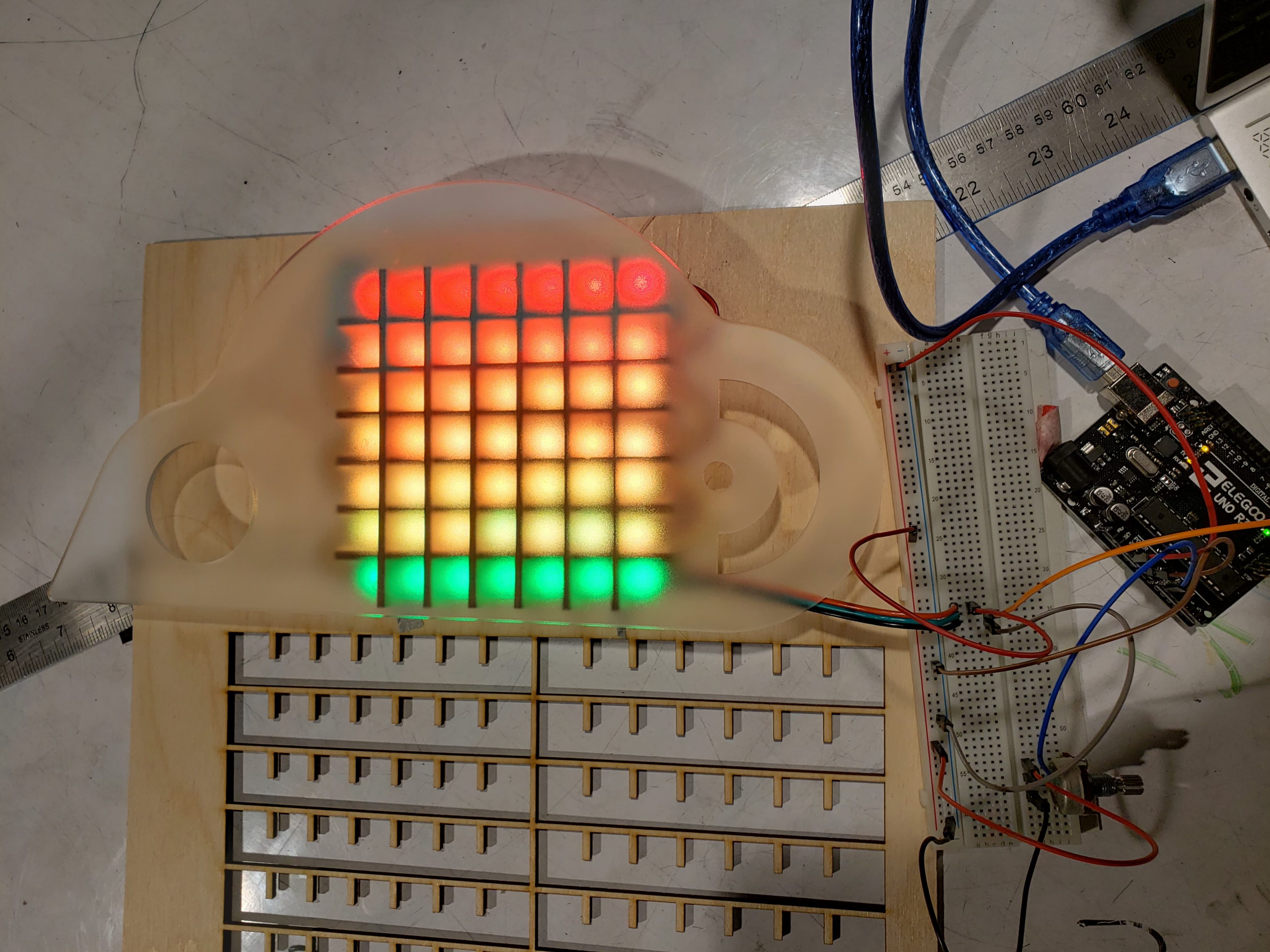
Light up of wind speed over “N” amount of minutes
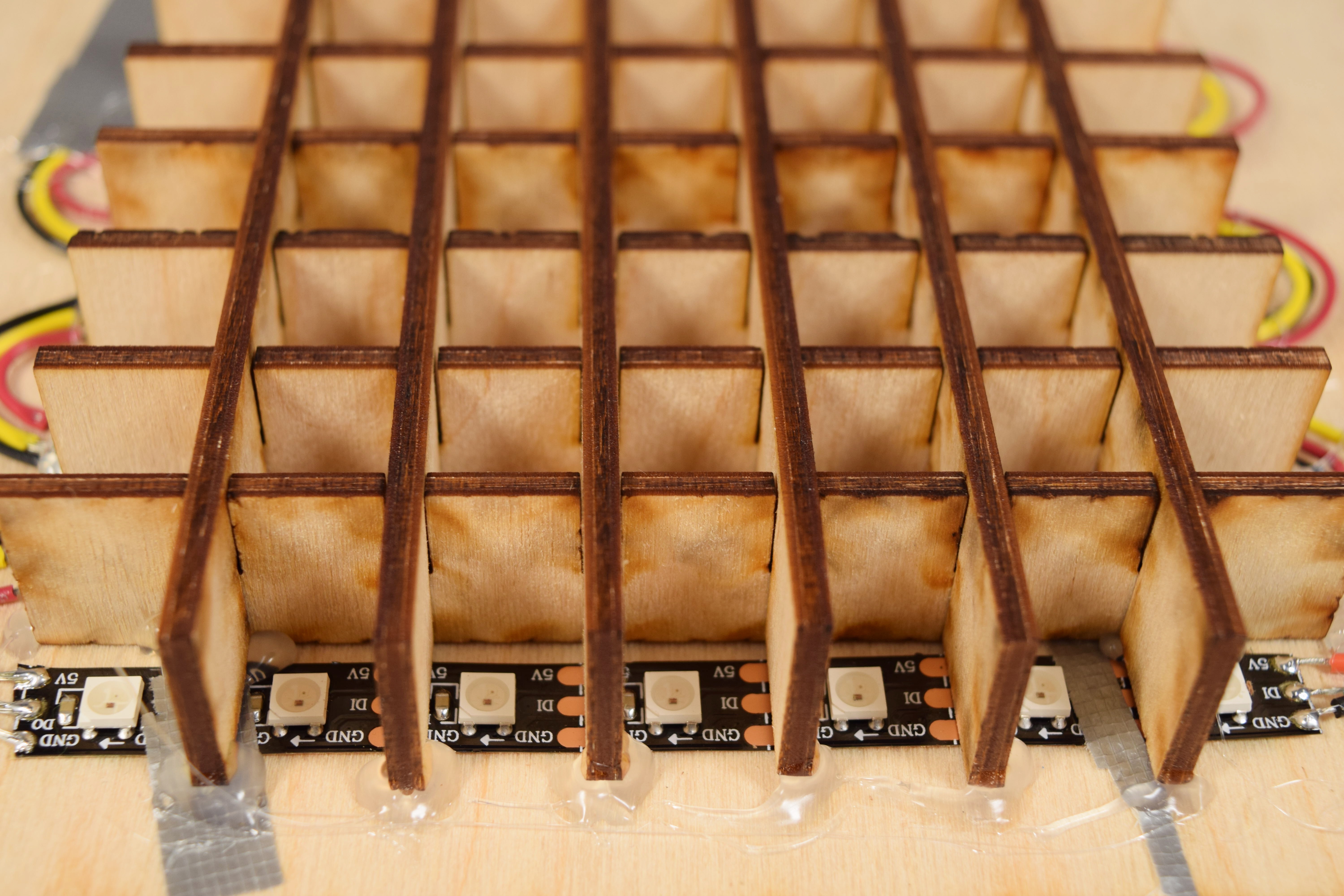
Close up of LED grid
- This personalized anemometer reads wind speeds outside and relays it in three main channels:
- Wind speeds within the past ~10 minutes
- Maximum wind speed of the day
- Current wind speed (instant)
- The “picture frame” display of the system will be housed within one’s home, preferably along a wall or other power outlet source, and the reader portion of the system will be strapped to a structurally sound arrangement that will allow the anemometer to read the wind speed, and Arduino to filter and relay the information.
Process
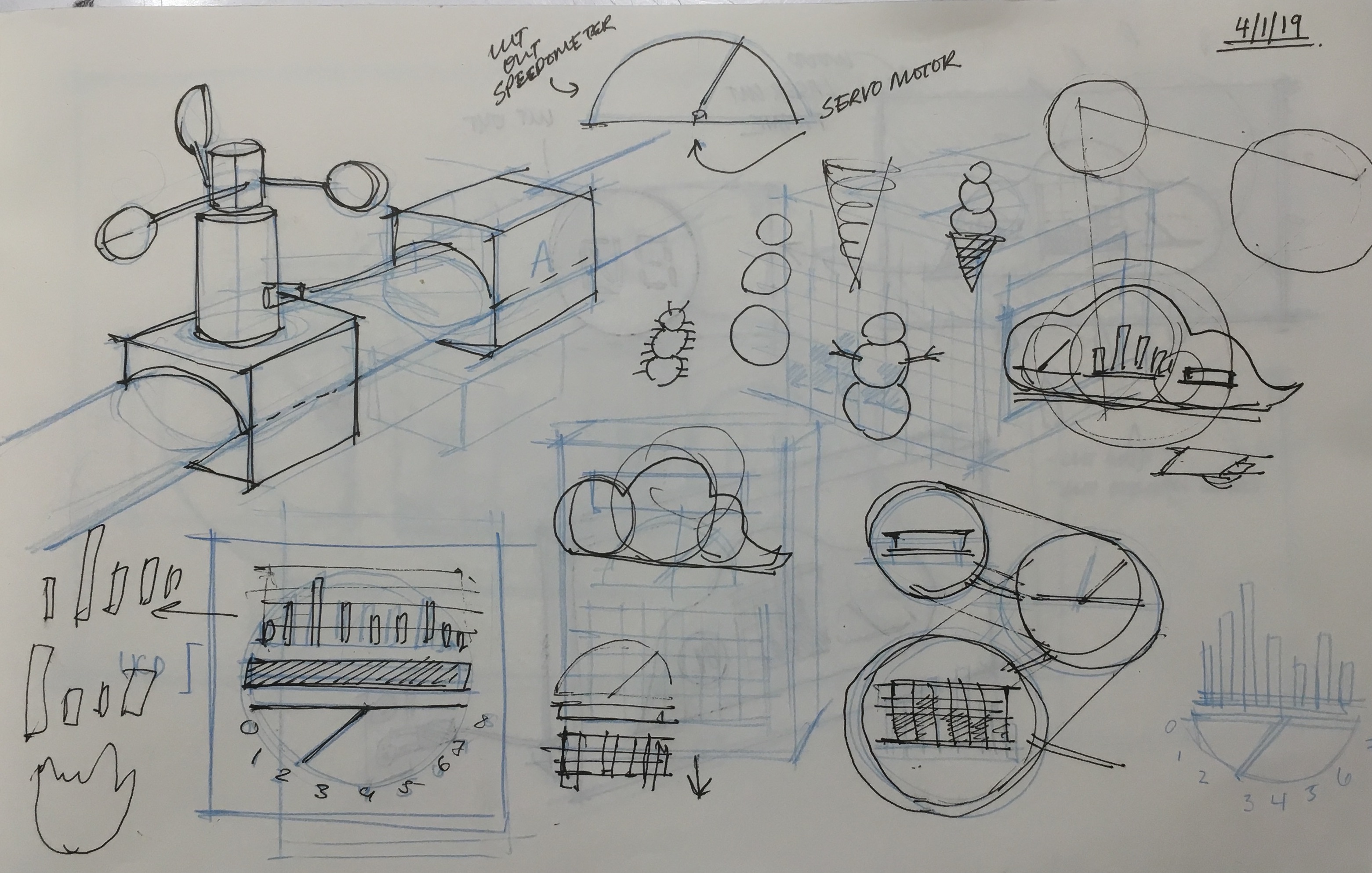
Initial Sketches
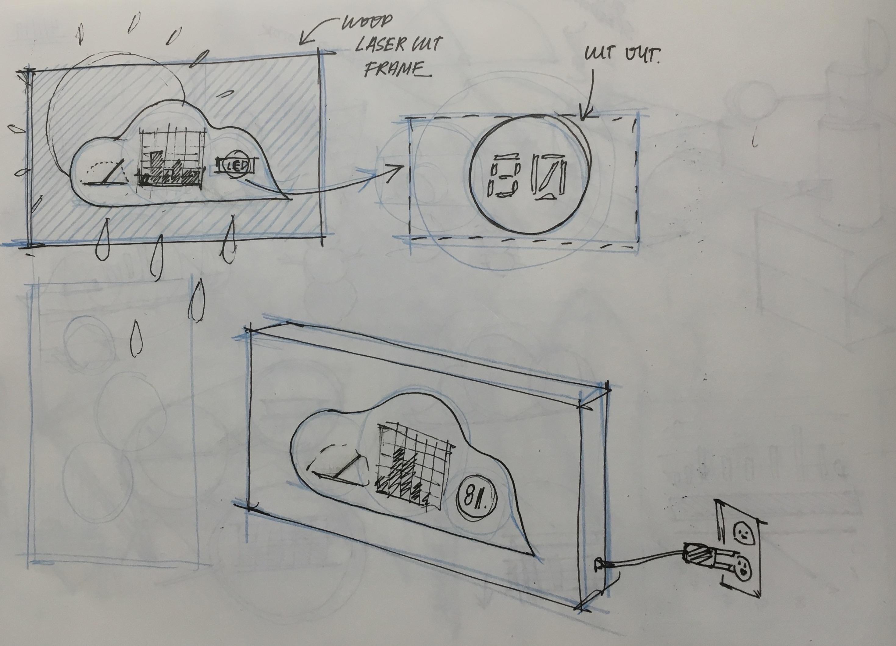
Developing cloud prototype
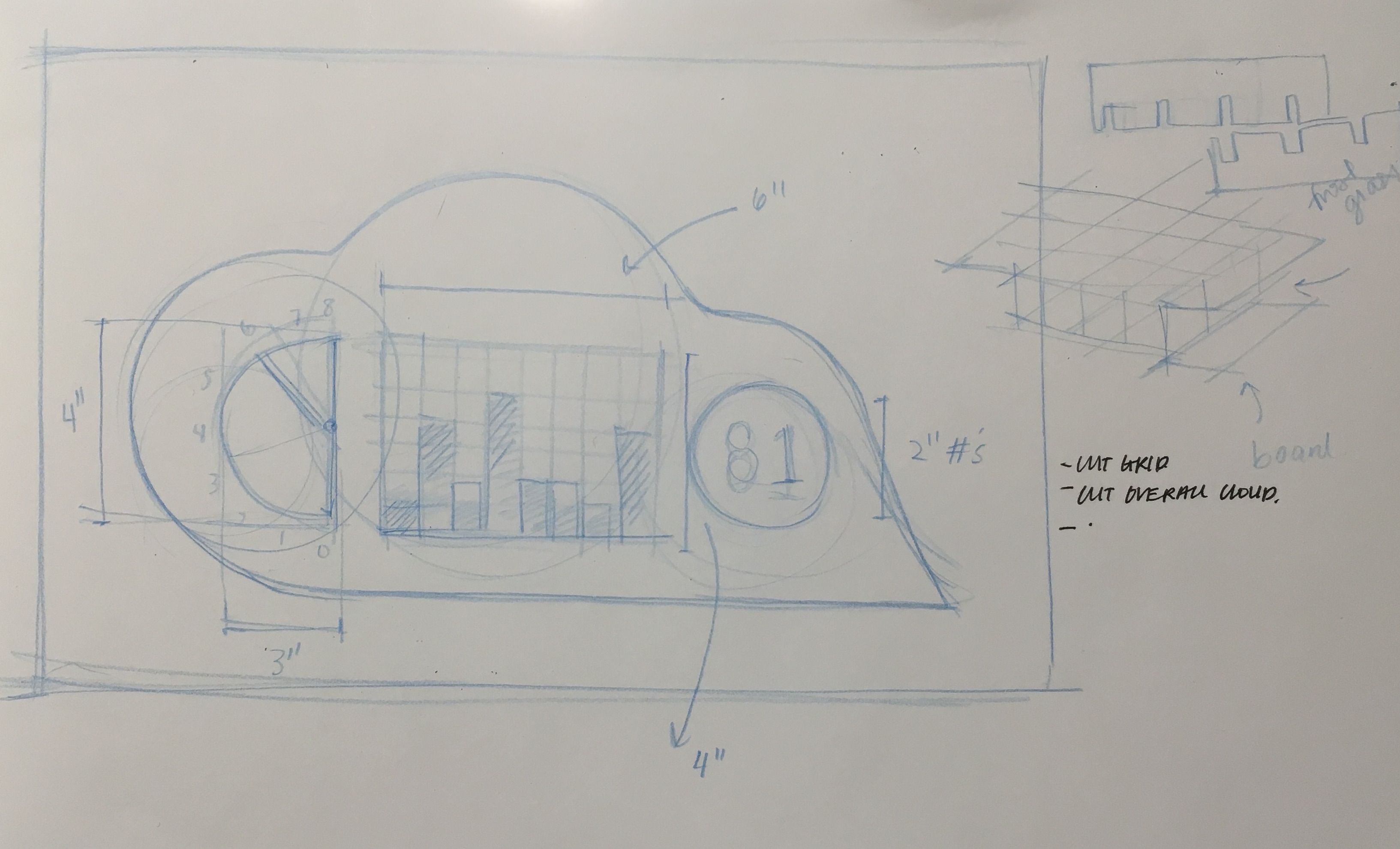
Figuring out dimensions + what cloud proportions should be
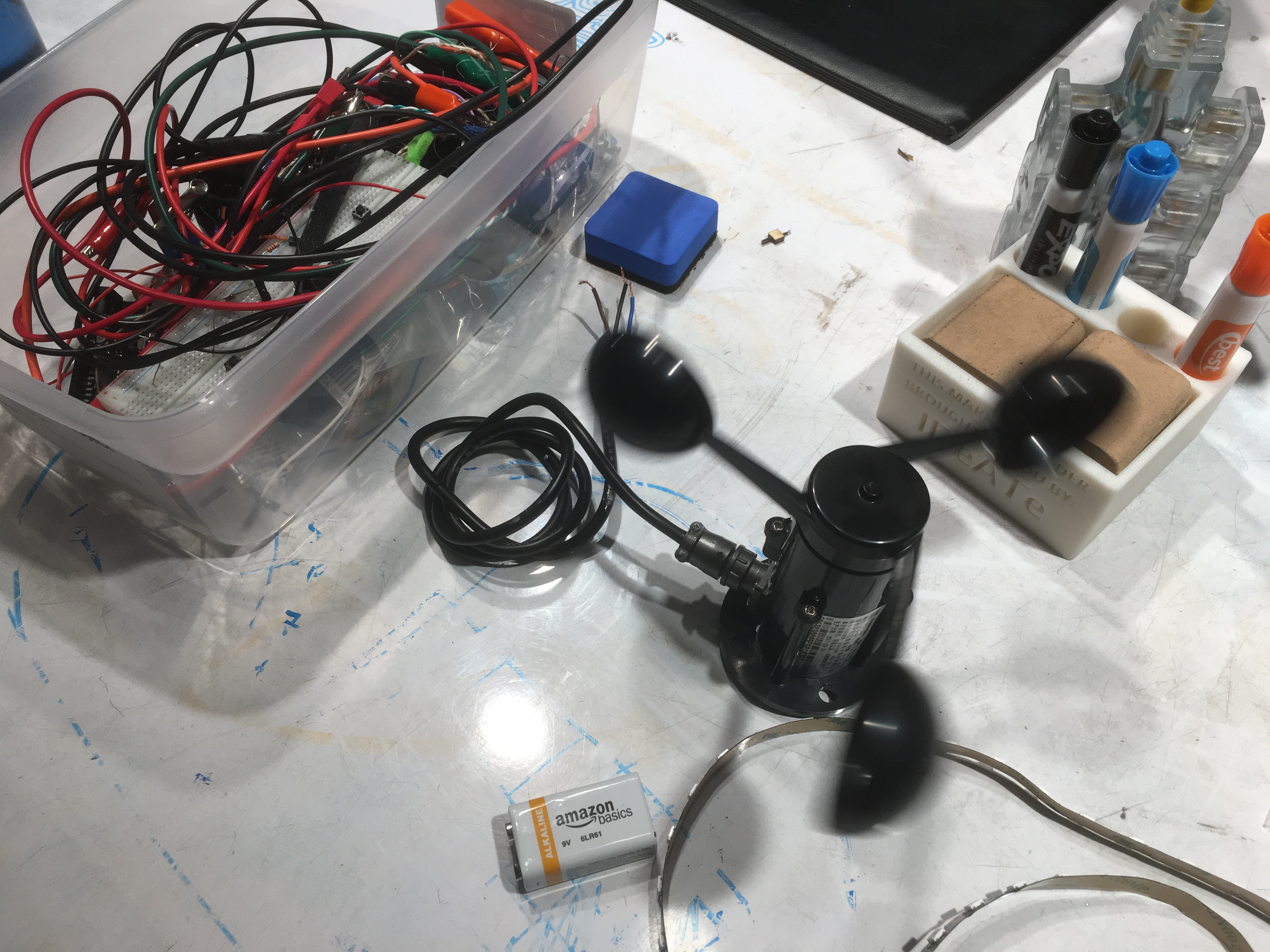
Playing around with anemometer (and pretending to be fake wind)
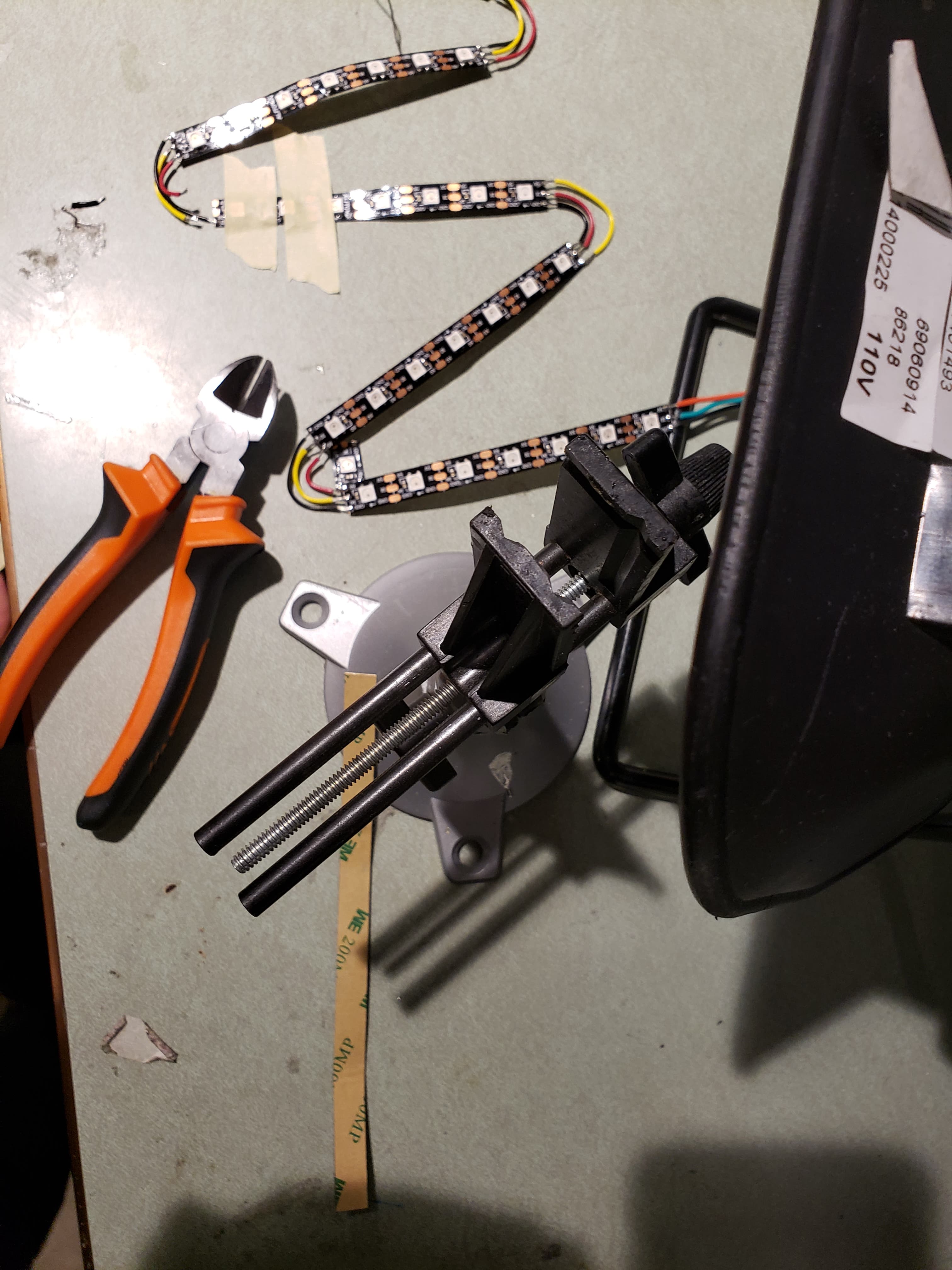
Soldering wires into grid structure
Exploring LED grid capabilities
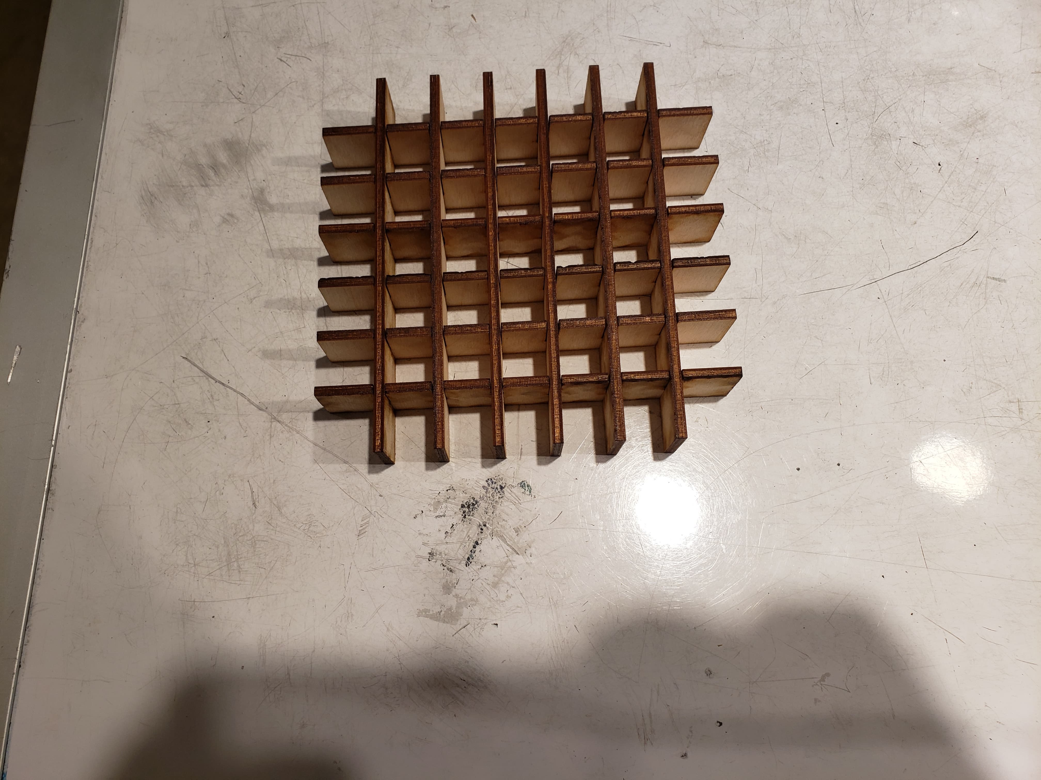
Wooden cut out grid to control LED lights from bleeding into each other.
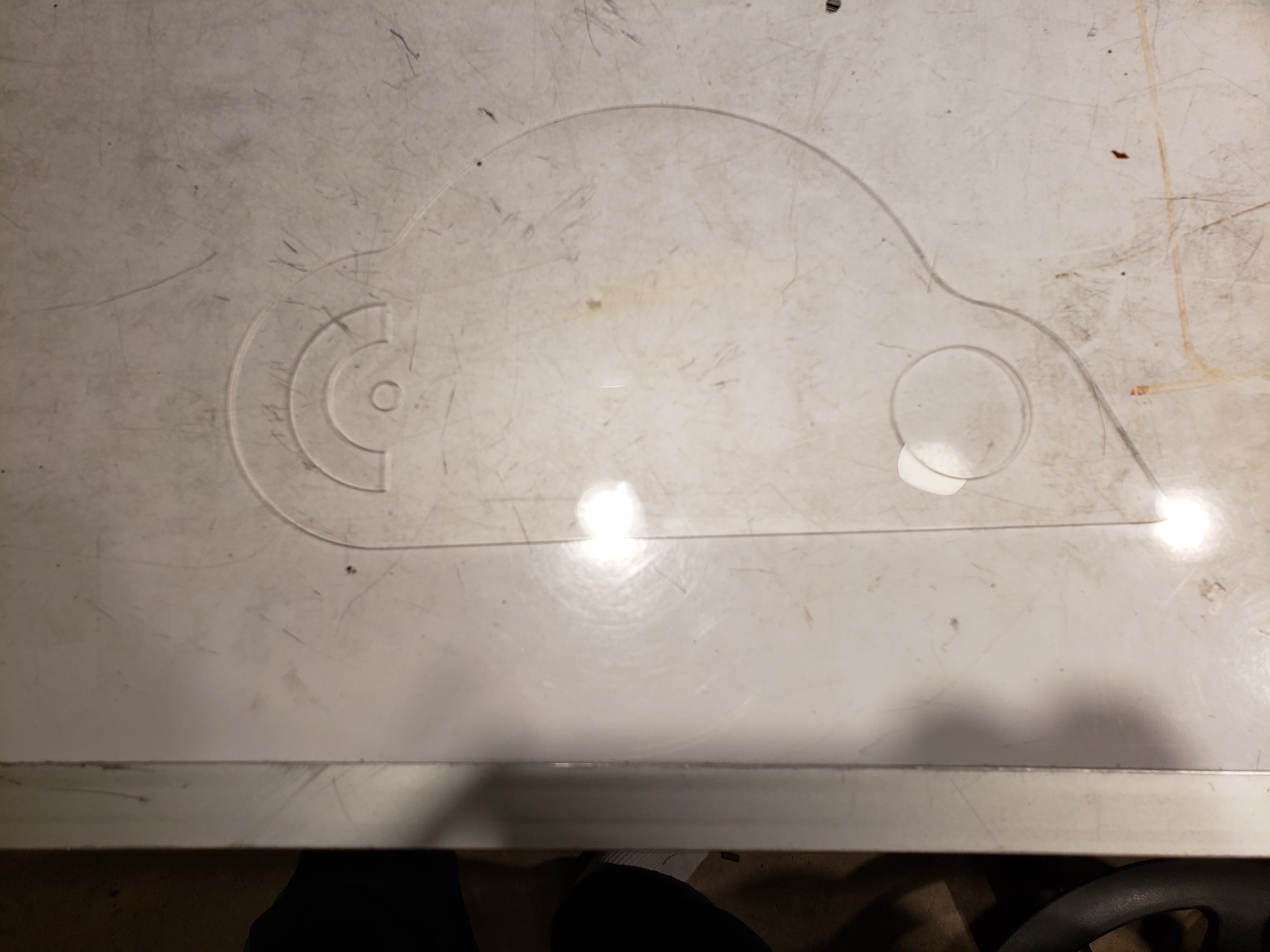
Acrylic cut cloud surface
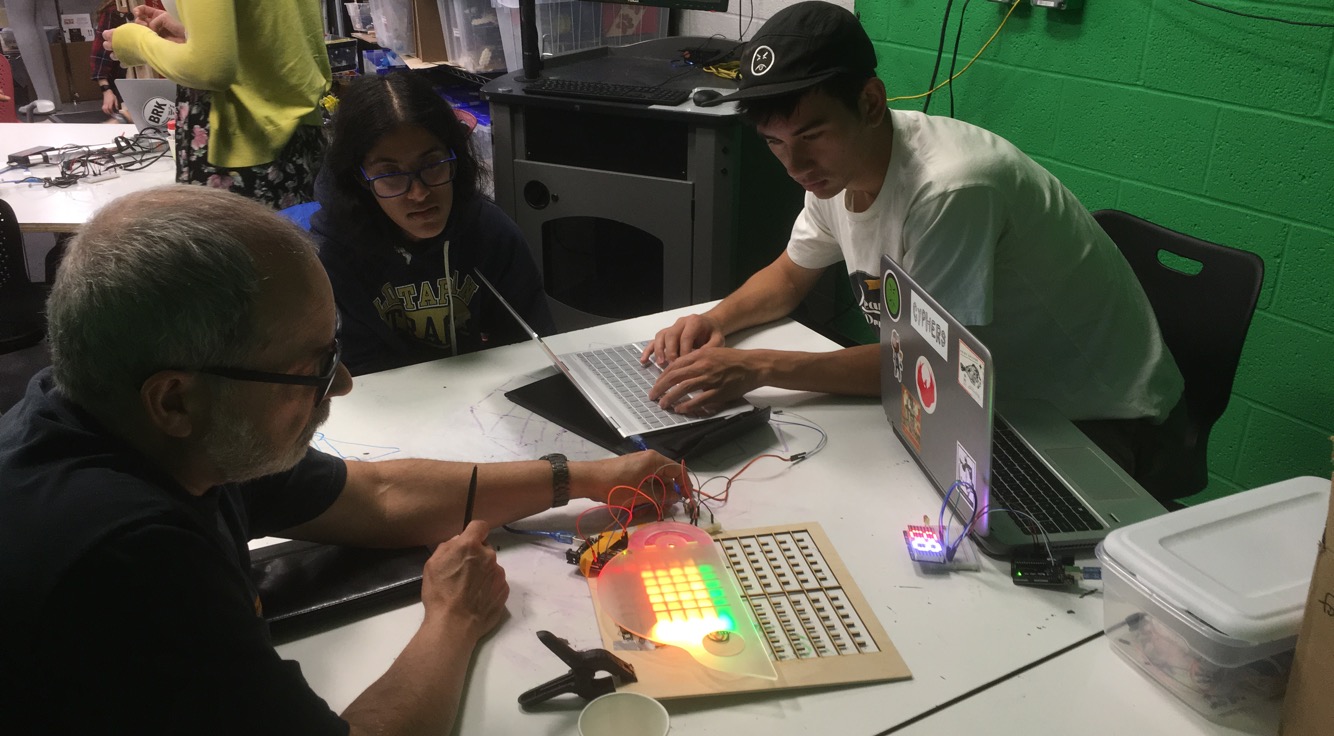
Meeting and chatting with Peter again for crit and mid-process feedback!
Discussion
Major Challenges
When creating this functioning prototype, we were challenged with how to personalize the visualization of data relayed in a visually engaging but not intrusive and obnoxious manner, how to adapt the components used to create a weather-proof deliverable, and errors and complexities that arose with trying to debug code that we fed into the LED systems. The largest and starting point of this project began with how to display the three points of interest (average wind speed, highest wind speed of the day, and wind speed within the past 10 or so minutes), in visually engaging and interesting ways that would not be so plain as to be simply text, akin to current on market anemometers. At first, we ideated around creating an interface that would also be housed outside, and be able to shine into the house from afar, however, decided against that as it would then also have to be of weather proof design and materials. We then brainstormed ideas of creating a picture-frame-esque mounted piece, that would display the three readings utilizing three different ways of interpreting data: 1. A “bar graph” like reading 2. A “speed dial” like reading and 3. A digital reading. By using three distinctly different ways of conveying data, we hope to create a contrast among the different types of data Peter takes interest in, despite them all being centered around wind speed. Ultimately, we settled on a graphic cloud-like design, with each set of data housed within one mound of the cloud. Moving forwards, we had to then design a box that would strap accordingly to the railing of Peter’s balcony, and serve as a sturdy platform as well as solid housing for the anemometer and Arduino to be housed within. Additionally, because the anemometer we purchased is one meant to detect high wind speeds, we are unable to directly prototype and test out what wind speeds would actually be like relayed onto our LED panels and digital reads. Instead, we have had to make do by attaching a potentiometer in efforts of playing around with the different levels of possible wind speeds. Aside from the design aspect, we realized that the motor didn’t function as expected when in the same code as the lights, so we will have to troubleshoot that some more. Looking back, we believe that there wasn’t enough power or current for both to run simultaneously; in previous projects, they used the same battery source, but ran in sequence so this particular problem did not arise.
Feedback from Meeting Again with Peter (April 8th)
After meeting again with Peter, we discussed more in depth the possible types of data that could be relayed across the three outputs, as well as how fluid we want the data to be manipulated in regards to controlling the duration of which data will be collected over. For example, Peter brought up that instead of having a digital reading of what the maximum wind speed within the past hour, he would rather have the servo motor point to the maximum wind speed of that particular day, which would then consistently go up as the day progressed, and then reset every night. This decision was based on the notion that 1. The servo motor could be quite loud and thus it would not be ideal to have it move often and 2. The information of maximum wind speed for the current day was more beneficial and interesting to Peter than the average wind speed within the past hour. Another possible element for change that Peter suggested was playing around with the lights, as he did not seem extremely keen on how bright they were. Initially, we had tried to diffuse this by utilizing a foggy acrylic, however, we might play around with creating a more so “line graph” out of the LED grid rather than a “bar graph” in order to alleviate the brightness, seeing as we can not manipulate the brightness. Furthermore, Peter thought it would be helpful if he were able to toggle between several features of what he wanted to display for the digital read, for example, to toggle between reading the instant wind speed at a given time versus reading the peak of the day.
As a group, we concluded that we would definitely want to hit upon most of Peter’s suggestions, as one of the primary points of this anemometer was the fact that it was personalized to Peter’s interests and curiosities in reading wind speeds. Because of that, we would like to accommodate the different features and data readings that he is most interested in knowing. We would also like to address the specific aesthetic needs that he has, as we would ideally want it to be non-intrusive as well, however, due to the limitations of materials and how certain materials give way to more customization than others, we will primarily focus on how the overall housing and structure of the product (ie. the cloud’s design, shape, dimension) before addressing the smaller aspects that have less give (ie. the brightness of the LED, the sound of how loud the servo motor is).
Moving Forwards
Moving forwards, we hope to integrate the different key features that Peter wishes to see in regards to the data readings from the wind anemometer. This includes creating a more personalized toggle system within the current wind speed readings, creating pieces and parts for the servo motor reading, and readjusting the way data will be conveyed through digital readings. We will also shift gears at a certain point to tackle the exterior portion of the system, and how to fasten the anemometer, Arduino, and radio module component accordingly so that the product can stay structurally sound amidst the outdoor winds and weather.
]]>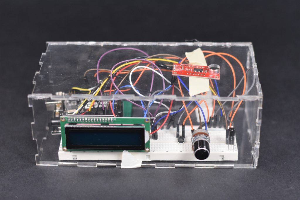
Top view of the prototype
Introduction:
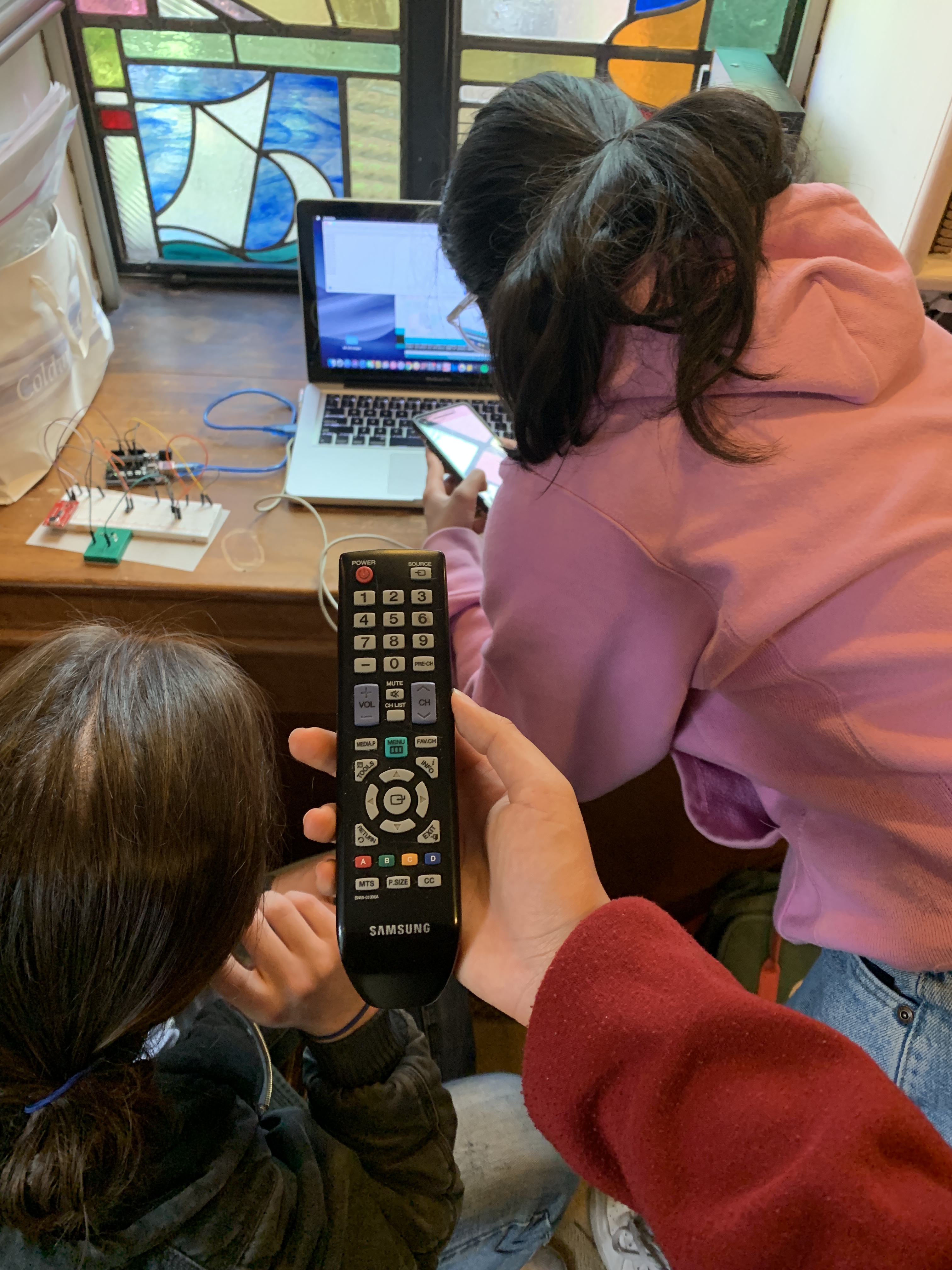
After interviewing Lois ( https://courses.ideate.cmu.edu/60-223/s2019/work/documentation-meeting-with-lois/ ) we determined that we would focus on designing a TV volume regulator for Lois and Irv’s den. A constant issue that Lois runs into is that when she is watching TV, as the commercials come on, the volume increases so much that Lois has to lower the volume using the remote.
Prototype:
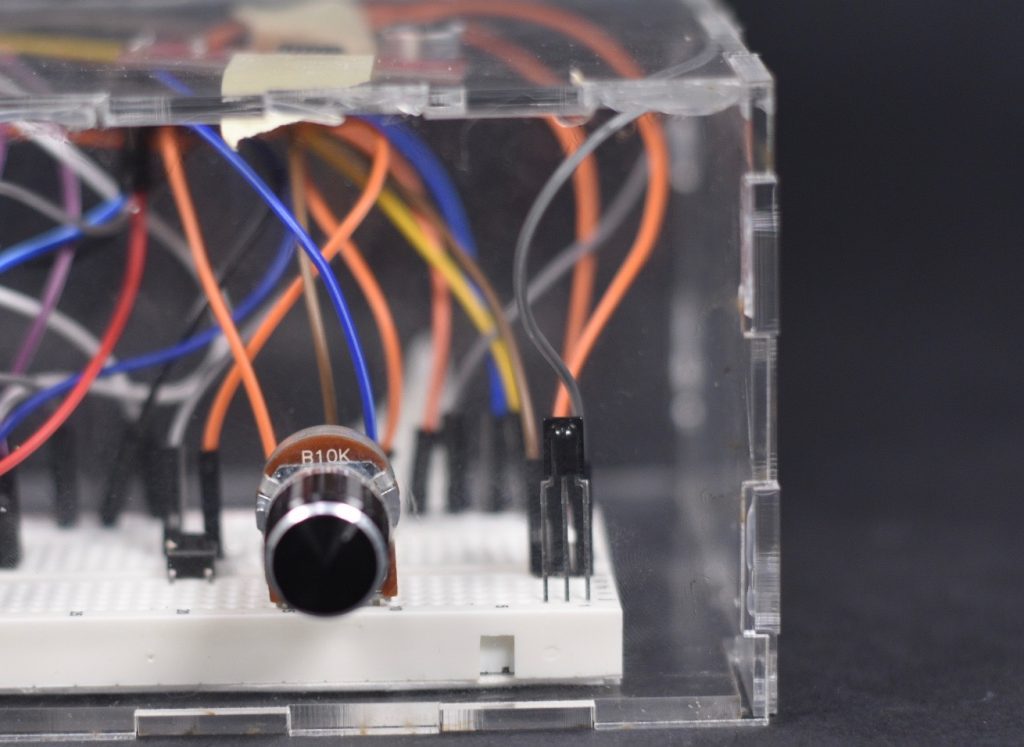
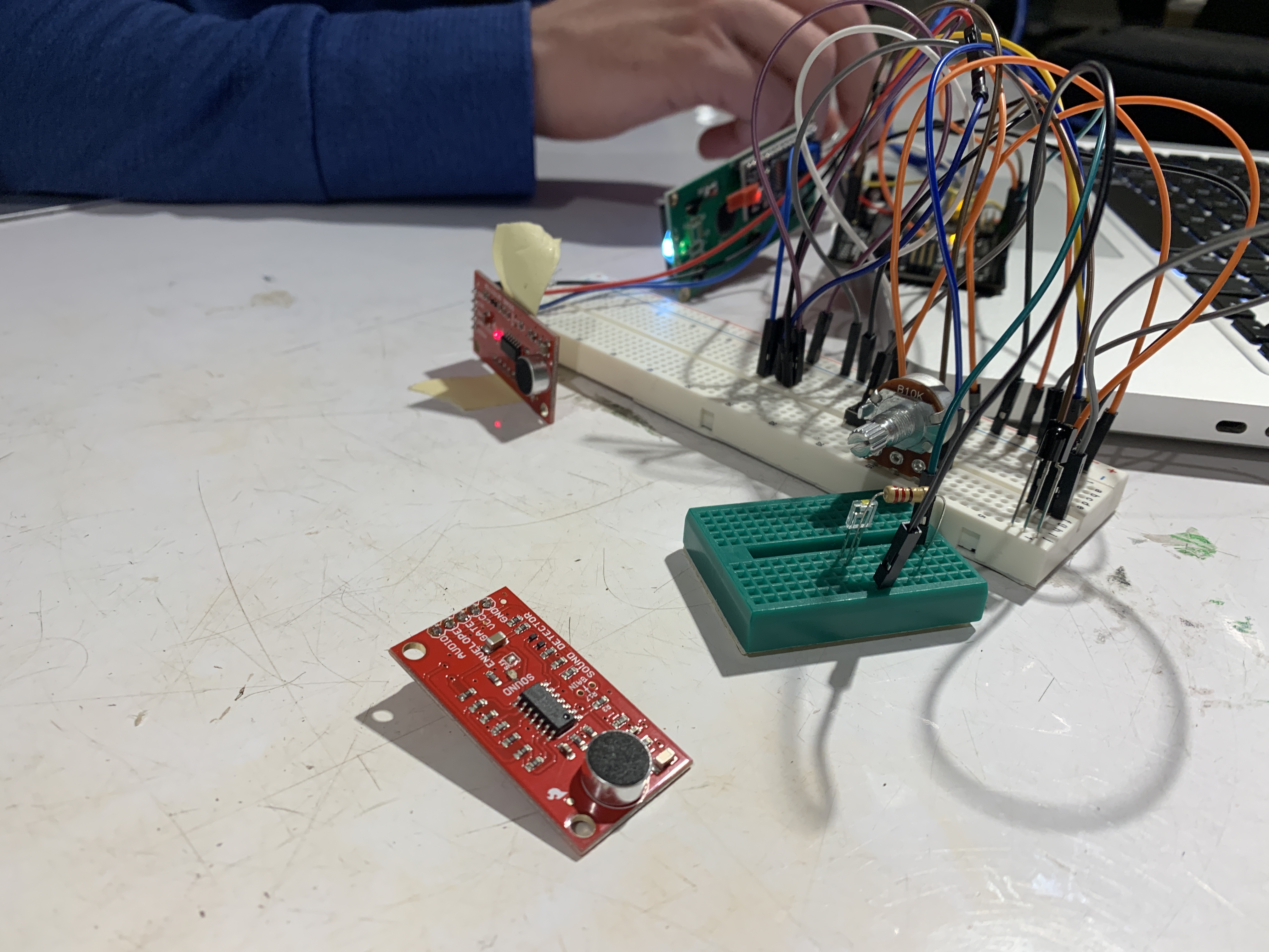
10k Potentiometer for volume threshold and IR transmitter for sending codes
Using the potentiometer, on the left side of the image, Lois or Irv can set the volume limit/volume threshold . In this current prototype, the number of the potentiometer is displayed on the LCD screen. This threshold indicates at what loudness the TV volume should be lowered. If the volume exceeds that limit, the sound module detects this and sends a message on the serial monitor. Otherwise, nothing is sent.
Audio sensor used to identify loudness
TURNING VOLUME DOWN!
Volume Reading: 63.00
Threshold Level: 45
Sending Remote Code: 0x1897926D
Serial montior output when volume is too high
The prototype can also recognize infrared codes sent by a TV remote.
Process:
After we determined what our project would do, we began to gather our materials and experiment with the IR transmitter and receiver. After getting the IR receiver to display the IR code of different remotes, as well as setting the sound detector up to detect the volume of the television, we were ready to visit Lois again to understand the specifications of her situation.
Testing IR transmitter + receiver, button is used to send code to the IR receiver. Sound detector is used to detect volume from TV
Visiting Lois (again):
In Lois den, we had a number of considerations to make in our second visit:
- Placement of Device within the space
Some places we considered for the placement of the device was the small space next to the television (pictured in the left). However we decided that if Lois or Irv wanted to change the threshold of the volume, the space next to the TV’s speaker would be inconvenient to access. We then considered the coffee table (pictured at the bottom) which served as a good compromise to both the proximity to the TV as well as the accessibility to Lois and Irv. However, Lois and Irv preferred not to have the device on the coffee table, so we dismissed that idea. In the end we decided to move the placement of the device to the back table (pictured in the right), due to the ease of access. One issue we do expect is the sound detection as well as the reliability IR transmitter, however once that issue arises, we will work that out with Lois.
1. Placement of Device: Panorama shot of Irv and Lois’ den to understand placement of the TV volume regulator
2. IR Code Reading
Since we had already set up the code to receive the IR code from various remotes, we also had to record the IR code of Lois’ remote buttons. We recorded the power, volume up, and volume down buttons.
2. IR Code Reading: Using Lois’ remote to find her remote’s IR code, we recorded her IR code for the different buttons
Lois’ TV Remote
3. Environmental Consideration in Final Design
We also took the consideration of our final design into account as we were in the space. We looked for inspiration in the electronics and the items within the space. The final design of the device should reflect the space and the intent.
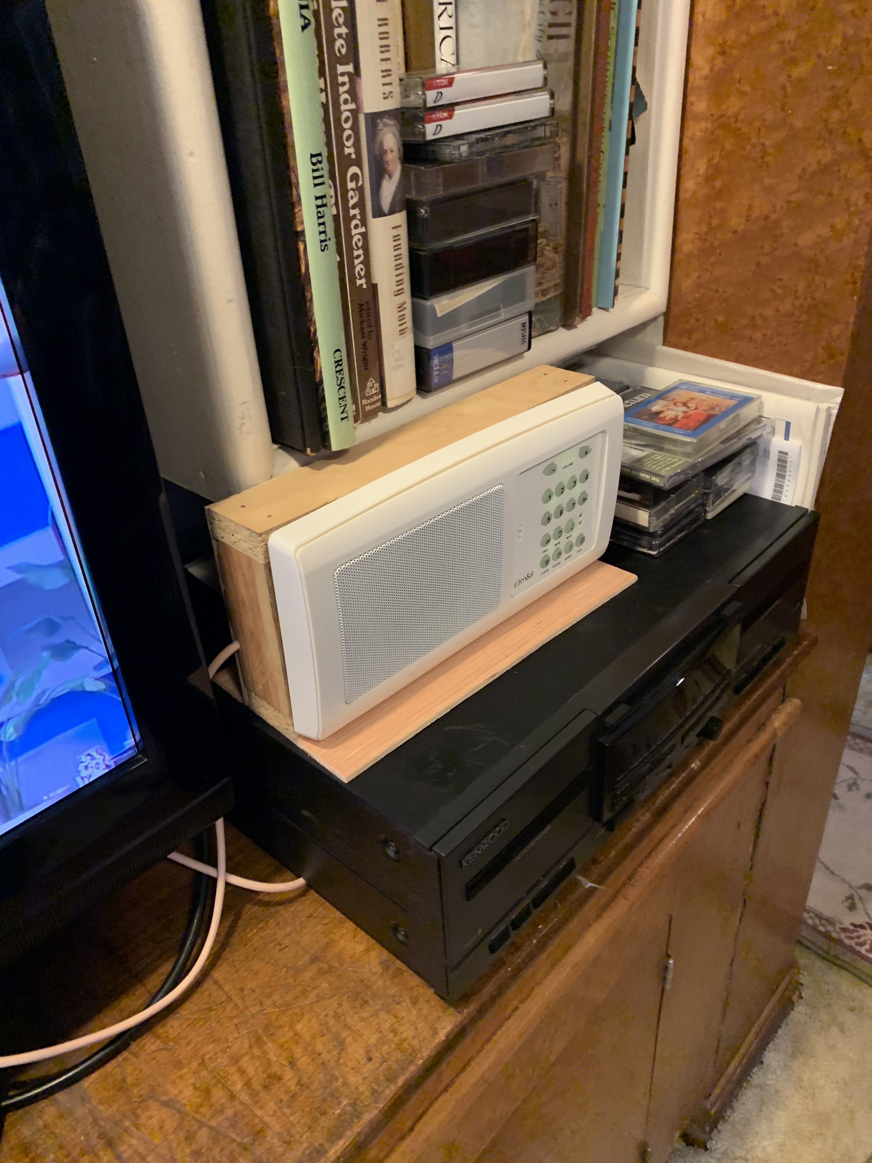
3. Environment in Context of Device: Looking at the style and form of other devices in Lois den. In this photo is the radio that Lois was listening to when we entered the space
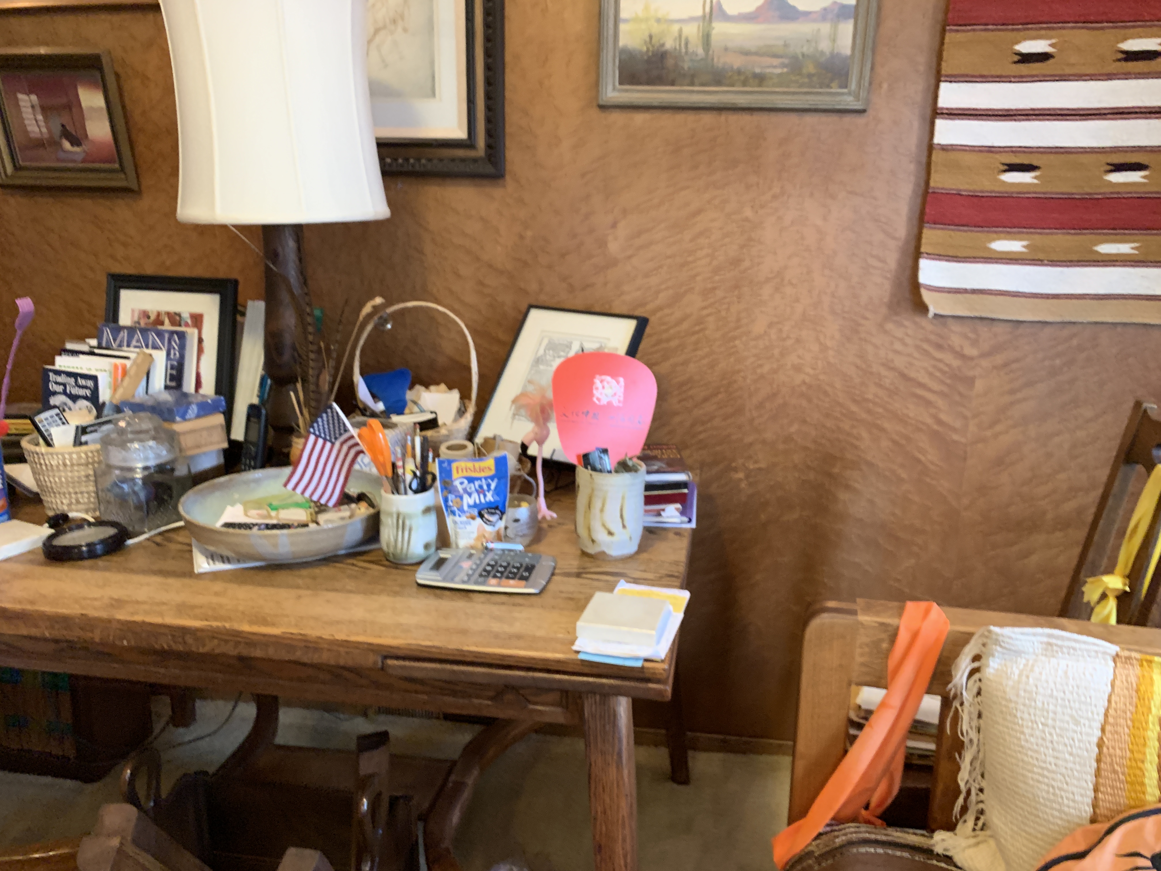
3. Environment in Context of Device: Items on back table
4. Testing volume on Lois’ television using the sound detector:
The sound detector seemed to have issues detecting the sound of the TV. It seemed to just be a sensitivity issue in the sensor, we decided to work on the sound detector sensitivity when we were back at CMU
Back at CMU:
After meeting with Lois we worked on the LCD screen and the potentiometer to set the threshold. We attempted to work with the projector and use the IR transmitter to change the volume displayed on the projector, however because we don’t have the correct part, we were unable to work on the device changing the volume reading.
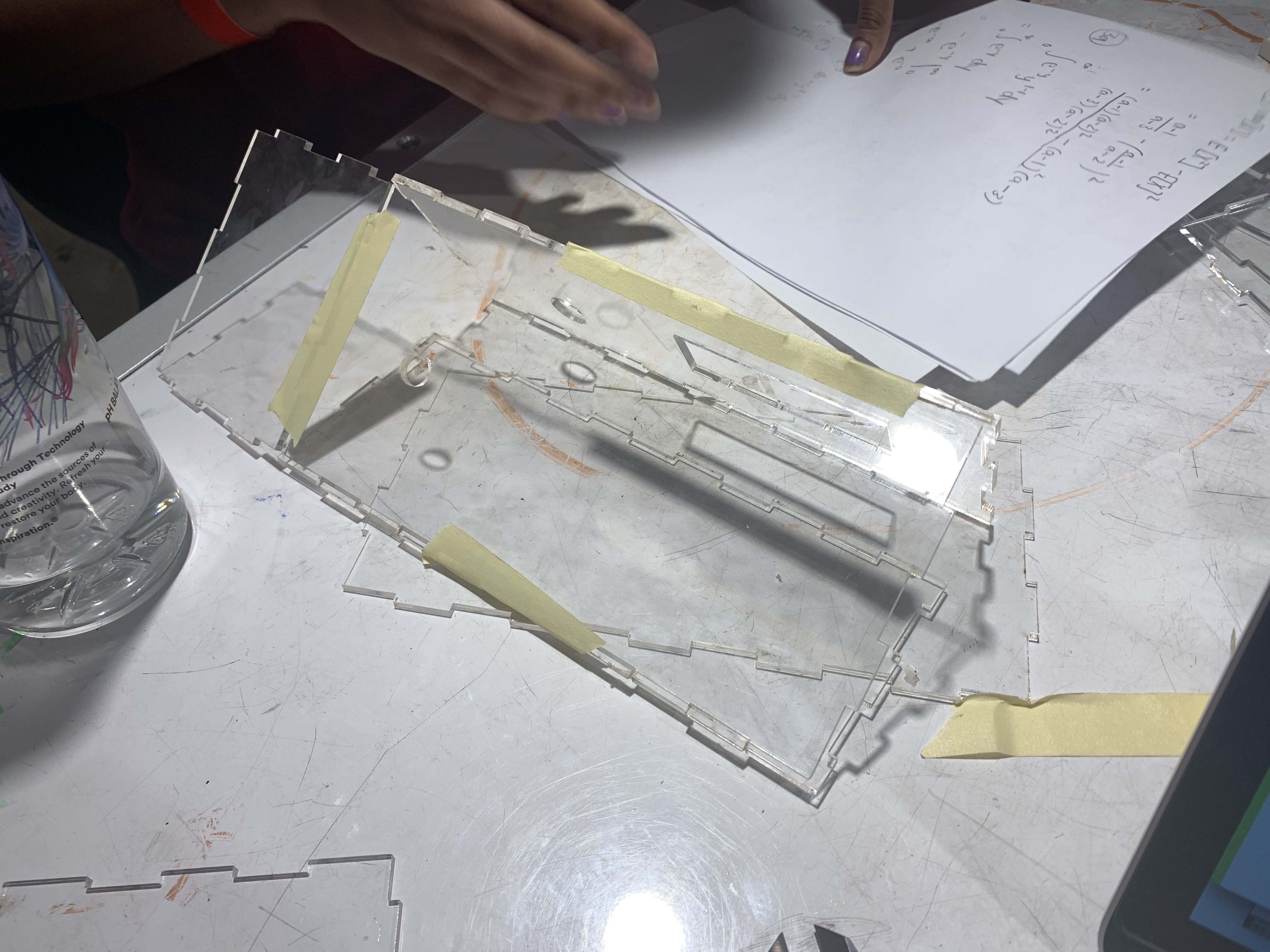
Constructing Acrylic Box, designed for the LCD screen, sound detector, and the potentiometer. (did not design for the Arduino USB cord)

Testing LCD screen, which would display the value of the potentiometer (1-100)
Sound detector issues: The sound detector we were using wasn’t sensitive/reliable enough to detect the volume of the television
Discussion:
Challenges: Some major issues we ran into while prototyping was the IR transmission not being able to transmit a code for the TV to change the volume. We determined the issue was not having the right part. We experimented with using the infrared proximity sensor and the reflective optical sensor, however ultimately determined that we need to get another part: the IR LED 940 Nanometer. Another issue we ran into was the sensitivity of the sound detector. Because our primary reason for this device is the volume, the sound detector needs to be able to detect 10-20 decibel changes, and the sound detector we were using was not sensitive enough for what we were trying to do.
During the critique on April 8, some questions we got from the general class were how the sound sensor would detect the change from commercial to the regular TV program and whether that change would be something that is detected by the timer or the sound sensor. Overall, because our code hadn’t loaded on the computer by the time of our presentation we didn’t get much feedback from the class but afterwards we were able to talk to Lois about whether she preferred to have the commercial breaks be timed or would there be a button that is pushed in order to raise the volume back up.
During the meeting with Lois, we primarily discussed the way for the volume regulator to either turn on or turn off the device. She said that it would be best if there was a button on the remote that she could push, so that when directed towards the device, it would turn the volume back up. We also discussed some visual representation of whether the device is working. She said she would prefer if the device is lowering the volume of the TV the NeoPixel will turn green, and if the device is increasing the volume, the NeoPixel will turn red. We then showed her some sketches we drew for the final form to see whether she would like this device in her den. She suggested rubber feet so that when Irv and Lois interact with the device, it won’t slide on the table. We asked her if she would like to have any other functions and she said she would prefer a mute button. We said that that can be possible with a rotary encoder. Overall, she was very happy with where we are going with the project and is excited to see how it would change her TV watching experience.
Future Considerations: The LCD screen was not what we wanted visually for the final product so we want to explore the NeoPixel to represent the threshold. We want to work on using the colors of the NeoPixel to represent the state of the device (whether the device is lowering or raising the volume). We want to add a mute capability in the rotary encoder and use the NeoPixel to visually indicate this as well.
In class meeting with Lois
Sketch of Final Design Concept
]]>