Ian Shei and Yael Canaan
-

Pressure > IR > motor double transducer -
Pressure > IR > motor double transducer -
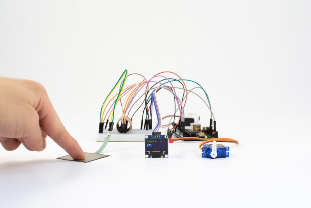
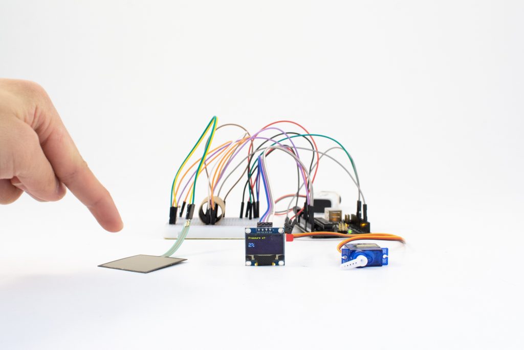
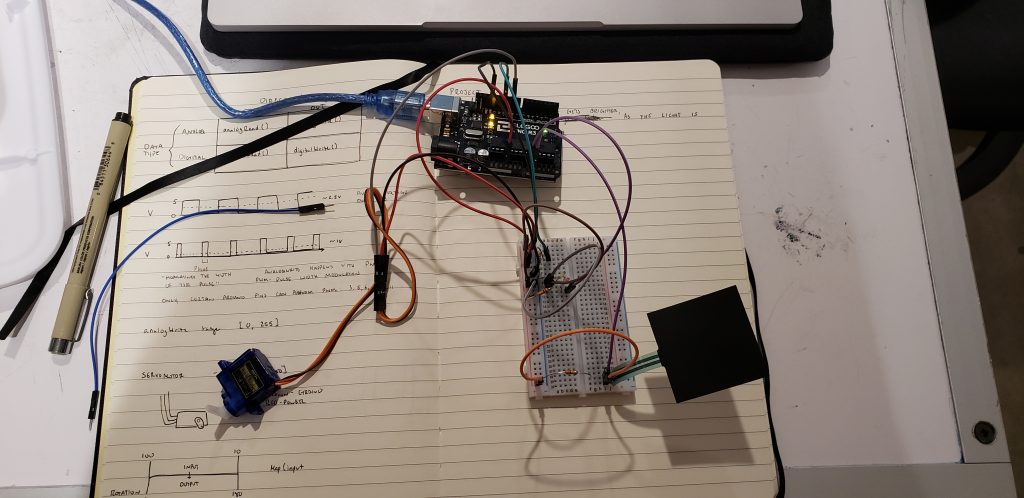
When pressure is applied to the FSR, the OLED display and servo motor update accordingly. -

A small cardboard tube with coated black interior shields the IR components from interference. -
Cardboard shield removed, showing the IR transmitter and receiver situated in close proximity.
Description
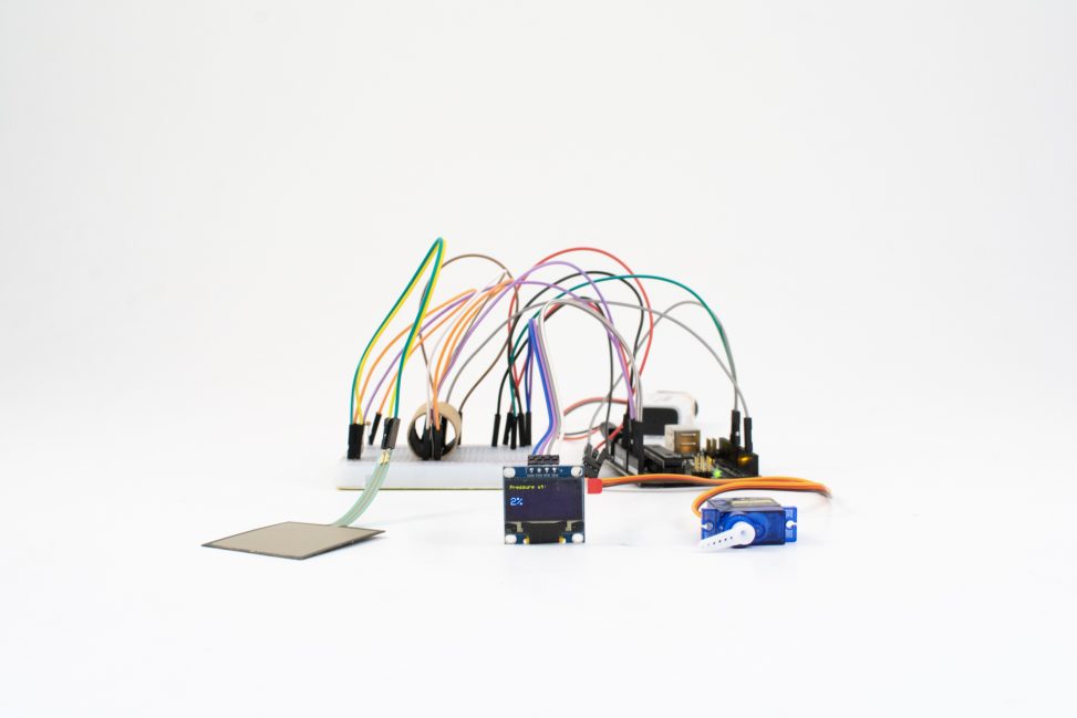
This project transfers a pressure signal from a force-sensing resistor (FSR) pad to an infrared (IR) transmitter which is picked up by an IR receiver. The amount of IR light received is then used to move a servo motor, acting as a dial-like analog display, to a corresponding angle. Additionally, a digital OLED display shows the amount of pressure being applied to the pressure pad as a percentage.
ELI5: A pad is pressed and the force is displayed on a monitor. Two lights communicate with each other based on how hard you press and the lights tell the motor how much to move.
Progress images
-
The sensor, IR, and motor working together. -
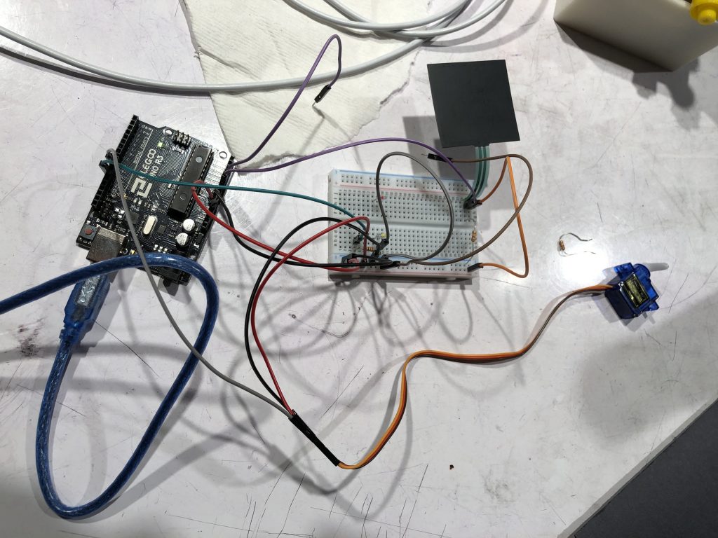
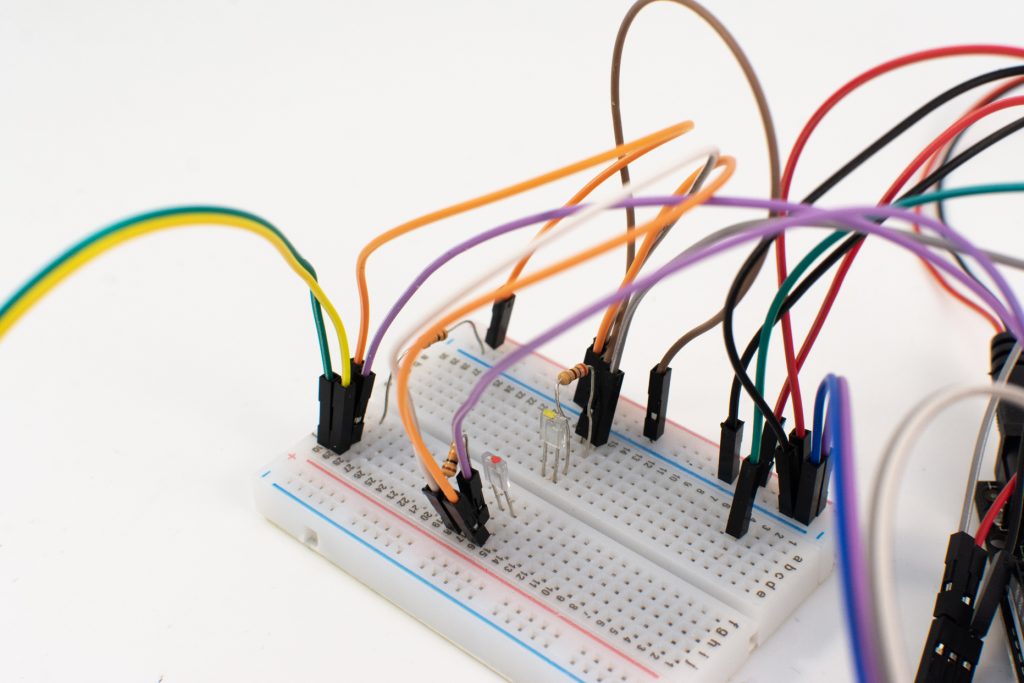
Preliminary wiring. Used to test functionality of IR components and perform readings of pressure outputted to Serial. -
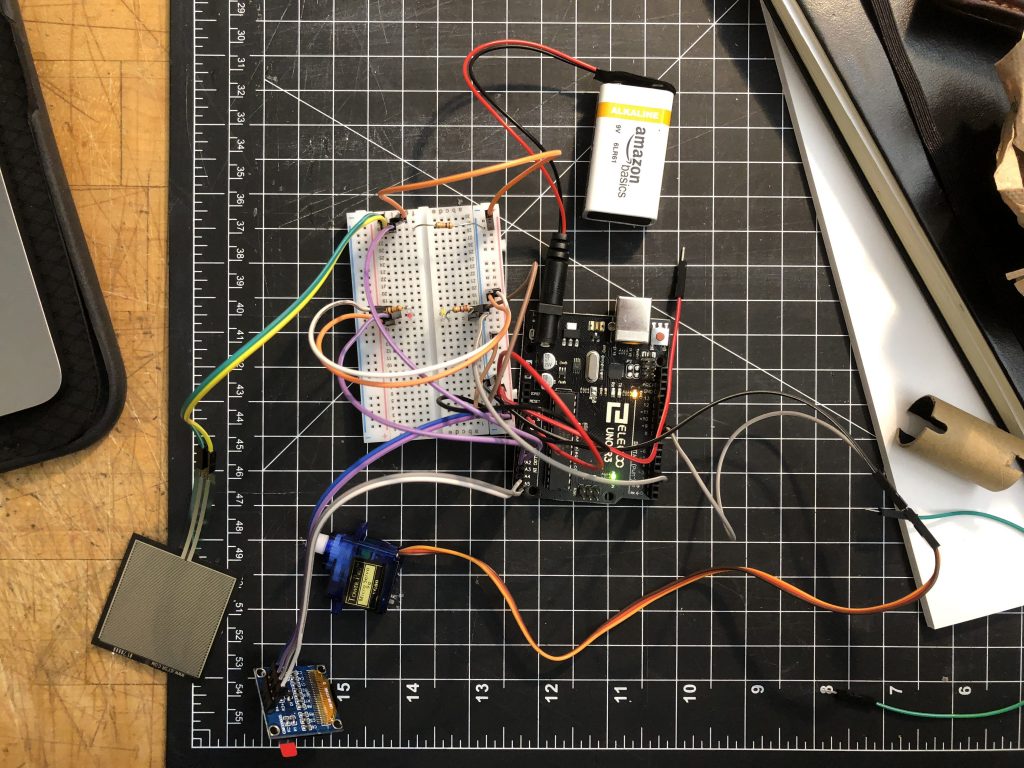
Final wiring. Note the repositioned IR components, FSR wiring extension, OLED display, and servo motor. IR shield removed to show parts.
Arranged from left to right: FSR pad, OLED display, servo motor. As more pressure is applied to the pad, the displayed percentage increases and the servo arm moves accordingly.
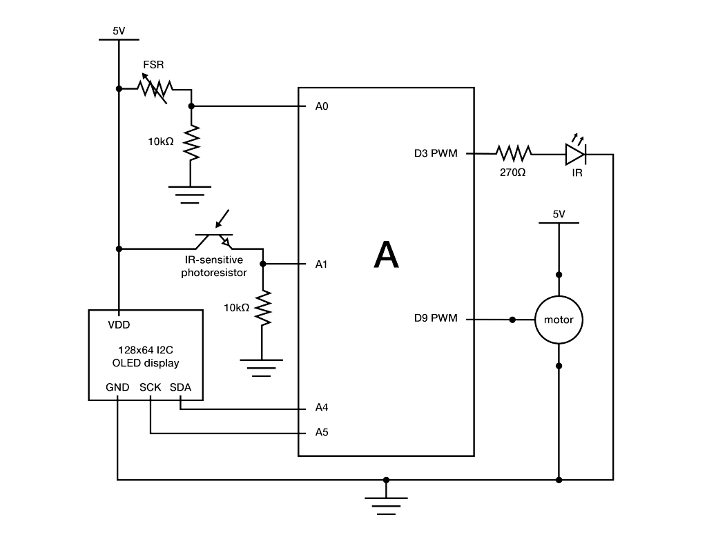
Schematic
Code
/*
 * Project 1 - double transducer
 *
 * Implements a double transducer: pressure input from an FSR is transduced
 * to IR output, the level of which
 * is read with an IR receiver and transduced to the movement of a servo
 * motor serving as an analog display.
 * An OLED display also shows the relative percentage of pressure direct
 * from the FSR pressure input.
 *
 * A basic smoothing algorithm is implemented twice to reduce jitter in OLED
 * display output and servo motor
 * movement.
 *
 * Smoothing implementation adapted from David A. Mellis & Tom Igoe's
 * example at http://www.arduino.cc/en/Tutorial/Smoothing.
 *
 * I2C display implementation adapted from Limor Fried/Ladyada for
 * Adafruit Industries.
 */

#include <SPI.h>
#include <Wire.h>
#include <Adafruit_GFX.h>
#include <Adafruit_SSD1306.h>

#define SCREEN_WIDTH 128 // OLED display width, in pixels
#define SCREEN_HEIGHT 64 // OLED display height, in pixels

// Declaration for an SSD1306 display connected to I2C (SDA, SCL pins)
#define OLED_RESET     4 // Reset pin # (or -1 if sharing Arduino reset pin)
Adafruit_SSD1306 display(SCREEN_WIDTH, SCREEN_HEIGHT, &Wire, OLED_RESET);

#include <Servo.h>

// pin assignments
const int PRESSURE_PIN = A0;
const int IR_TRANSMIT = 3;
const int IR_RECEIVE = A1;
const int MOTOR_PIN = 9;
Servo motor1;

int force;
int ir_received;

// constants for sensor inputs and outputs
const int PRESSURE_MIN = 0;
const int PRESSURE_MAX = 1023;
const int LED_MIN = 0;
const int LED_MAX = 255;
const int MOTOR_MIN = 0;
const int MOTOR_MAX = 180;
const int IR_RECEIVE_MIN = 0;
const int IR_RECEIVE_MAX = 1023;

// setup for pressure display smoothing
const int pressureNumReadings = 15; // number of pressure readings over which to average
int pressureReadings[pressureNumReadings];
int pressureReadIndex = 0;
int pressureTotal = 0;
int pressureAverage = 0;

// setup for motor smoothing
const int motorNumReadings = 10; // number of motor inputs over which to average
int motorReadings[motorNumReadings];
int motorReadIndex = 0;
int motorTotal = 0;
int motorAverage = 0;
String percentage;

void setup() {
  // put your setup code here, to run once:
  pinMode(IR_TRANSMIT, OUTPUT);
  pinMode(IR_RECEIVE, INPUT);
  motor1.attach(MOTOR_PIN);
  motor1.write(0);

  // for motor smoothing; array setup
  for (int thisMotorReading = 0; thisMotorReading < motorNumReadings; thisMotorReading++) {
    motorReadings[thisMotorReading] = 0;
  }

  // for pressure display smoothing; array setup
  for (int thisPressureReading = 0; thisPressureReading < pressureNumReadings; thisPressureReading++) {
    pressureReadings[thisPressureReading] = 0;
  }

  Serial.begin(9600);


 // SSD1306_SWITCHCAPVCC = generate display voltage from 3.3V internally
  if(!display.begin(SSD1306_SWITCHCAPVCC, 0x3C)) { // Address 0x3C for 128x64
    Serial.println(F("SSD1306 allocation failed"));
    for(;;); // Don't proceed, loop forever
  }
}

void loop() {
  // put your main code here, to run repeatedly:
  force = analogRead(PRESSURE_PIN); // reading pressure level from FSR
  ir_received = analogRead(IR_RECEIVE);

  // IR LED transmits brightness according to pressure level on FSR
  analogWrite(IR_TRANSMIT, map(force, PRESSURE_MIN, PRESSURE_MAX, LED_MIN, LED_MAX));

  ir_received = analogRead(IR_RECEIVE); // IR receiver receives IR from IR LED relative to transmit brightness

  // smoothing to decrease jerking of servo motor - constant running average over 10 readings
  motorTotal = motorTotal - motorReadings[motorReadIndex];
  motorReadings[motorReadIndex] = map(ir_received, IR_RECEIVE_MIN, IR_RECEIVE_MAX, MOTOR_MIN, MOTOR_MAX); // mapping IR receiver range to motor movement range
  motorTotal = motorTotal + motorReadings[motorReadIndex];
  motorReadIndex = motorReadIndex + 1;

  if (motorReadIndex >= motorNumReadings) {
    motorReadIndex = 0;
  }

  // smoothing for display of pressure percentage on OLED panel - constant running average over 15 readings
  pressureTotal = pressureTotal - pressureReadings[pressureReadIndex];
  pressureReadings[pressureReadIndex] = map(force, PRESSURE_MIN, PRESSURE_MAX, 0, 100); // displaying pressure as percentage by mapping pressure readings
  pressureTotal = pressureTotal + pressureReadings[pressureReadIndex];
  pressureReadIndex = pressureReadIndex + 1;

  if (pressureReadIndex >= pressureNumReadings) {
    pressureReadIndex = 0;
  }

  // calculating average values for motor and OLED display output
  motorAverage = motorTotal / motorNumReadings;
  pressureAverage = pressureTotal / pressureNumReadings;
  delay(15);

  motor1.write(motorAverage);
  percentage = String(pressureAverage);
  Serial.println(percentage);
  testdrawchar(); // calls display function to show relative pressure as percentage on OLED display
}

// display function to show relative pressure as precentage on OLED display
void testdrawchar(void) {
  display.clearDisplay();
  display.setTextSize(1);
  display.setTextColor(WHITE);
  display.setCursor(0, 0);
  display.println("Pressure at: ");

  display.setTextSize(2);
  display.setTextColor(WHITE);
  display.setCursor(0, 24);
  display.println(percentage + "%");

  display.display();
}
Discussion
Yael~
I worked alone during the in class work period. At first I struggled a lot, especially due to being intimidated by how much I had to do on my own. I managed to get through the work session using Dan’s help as well as the internet. The use of many new parts at the same time was confusing and difficult for me, I ended up tackling it by integrating each new component separately. Some of the components were difficult because the rules for use contradicted previously learned material, such as the IF receiver – the longer pin had to be connected to ground. In the future I hope to expand my library of components and different tools that I will be able to use in more complex projects as well as my studio projects.
Ian:
Day 1 (4 hours)
When the project was handed off to me after the in-class work session, there were issues that had to be troubleshooted and corrected. First, while pressure readings from the FSR were being displayed in Serial output, since the IR receiver circuit lacked a resistor, values were all over the place and thus the servo motor (which derives it position from the amount of IR light received) was moving in an erratic, seemingly-random manner. Additionally, I altered the lines in code that accounted for the amount of IR light emitted from the LED to use analogWrite so that brightness would vary when plugged into a PWM pin on the Arduino. I also rewired the components on the board and to the Arduino so that the IR components would directly face each other. After some trial and error resulting in this setup, the next thing to tackle was constructing the code to be well-optimized for the application.
In theory, pressure values off the FSR can be directly applied to servo motor output using the map() function . However, given the requirement of a “double transducer,” the intermediate step of IR transmit and receive inevitably adds noise to the output – undesirable if one’s goal is to transduce one value to another. The first method applied to reduce noise was to shield the rearranged IR components with a cardboard tube, whose inside face I coated in black ink – the objective being to block as much interference from outside the system as possible. Secondly, I adapted Mellis and Igoe’s basic smoothing algorithm such that a running average of 10 IR receiver readings is written to change the servo’s position. Although this did not eliminate all jitter in the motor’s movement, it greatly reduced it to an acceptable (non-annoying) level. The number of values over which to average for was chosen as a balance between output stability and responsiveness (more values to average = more input lag).
Day 2 (1.5 hours)
As a “for-fun” bonus, a 128×64 OLED display was added to the project to display live pressure values as a percentage; the harder the FSR is pressed, the greater the percentage. Implementing an I2C digital display for the first time in a project presented a bit of a challenge since many implementations exist and are often specialized towards specific display components. Fortunately, I was able to ascertain and adapt the necessary function from the Adafruit I2C library in order to display text. Like the servo motor output, the displayed pressure percentage was also smoothed over a running average of 15 values (determined to be the best of both stability and responsiveness). Adding the display followed a sort of theme with the project as a whole – taking advantage of FOSS resources to wire all the components as well as integrate them in code.
Days 3 & 4 (2.5 hours)
After the project was completed and presented in class, I photographed it using a lighting cube in my design studio, post-processed the images in Lightroom, and made a wiring diagram in Illustrator describing the electronics. Given more time, possible refinements include soldering components together and creating a housing to yield a higher degree of refinement. An intriguing extension includes testing different, more advanced smoothing algorithms in order to remove any discernible jitter in the outputs.
Comments are closed.