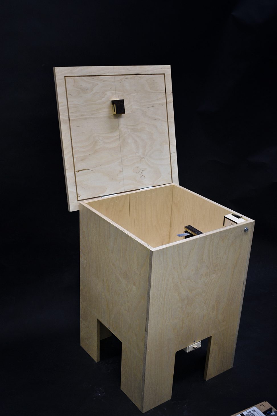

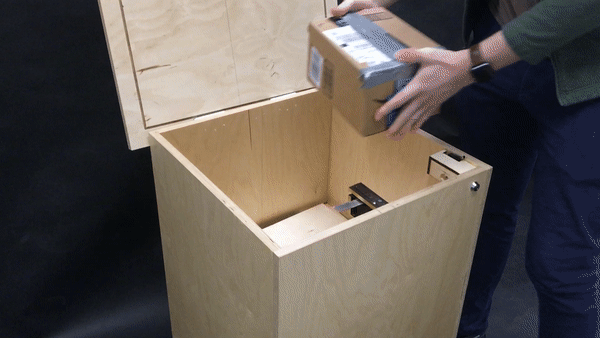
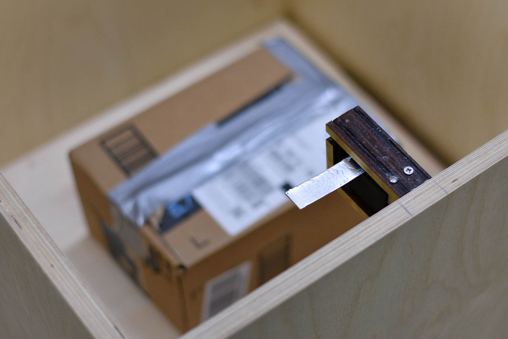
The open box with features the the locking mechanism servo towards the middle and the groove at the top.
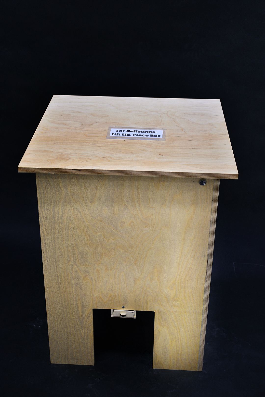
The closed package-box which has a sign for the delivery drivers “For deliveries. Lift Lid. Place Box.”
Brief Summary of work:
Our names are George, Yael and Enock, and for our final project we collaborated with Emily, a Carnegie Mellon University OSHER student, to try and improve a facet of her life. Though our collaborative discussions produced several promising ideas and directions, we eventually settled on attempting to solve Emily’s package theft problem. We learned through our in person meetings with her that she not only lives in a corner street house, but that her patio is fully exposed to potential package stealing crimes of opportunity. These issues were further exacerbated by school bus stops across the street from her house, making her area highly trafficked during prime package delivery times. In fact, she reflected more than once about children walking home from the bus and stopping at her property to steal packages. We refer the interested reader here for additional information and motivation behind our choosing this project. Soon after meeting with Emily, we created our initial prototype device, which centered around having a ‘smart lock’ that could recognize when a package has been placed and lock accordingly. We then had the opportunity to not only demo it to our peers and her, but also receive valuable feedback about the best ways to improve our project so that it may better Emily’s life. A thorough discussion of our prototype and critique can be found here, while below we present our finial documentation for the final version of our package thief prevention box.
What We Built:
We designed a large lofted and raised weather resistant wooden anti-theft box designed to sit on a porch and prevent packages from being stolen. At the core of our box is a pressure sensor which serves to detect whether or not packages have been placed inside. Once a package has been placed, the device automatically locks and waits until its owner unlocks it with a key. In its unlocked state, the owner is able to not only collect their package(s) from inside, but can also recalibrate the package sensing in case it is no longer accurately detecting packages. Once the package has been taken out and/or the sensing has been recalibrated, the owner turns the key to set the device back into the ‘package detection’ state. The device is powered by four batteries found in a cubby below its floating base, and further doubles as a surface to put items on, allowing the owner to place bags on it while opening the front door.
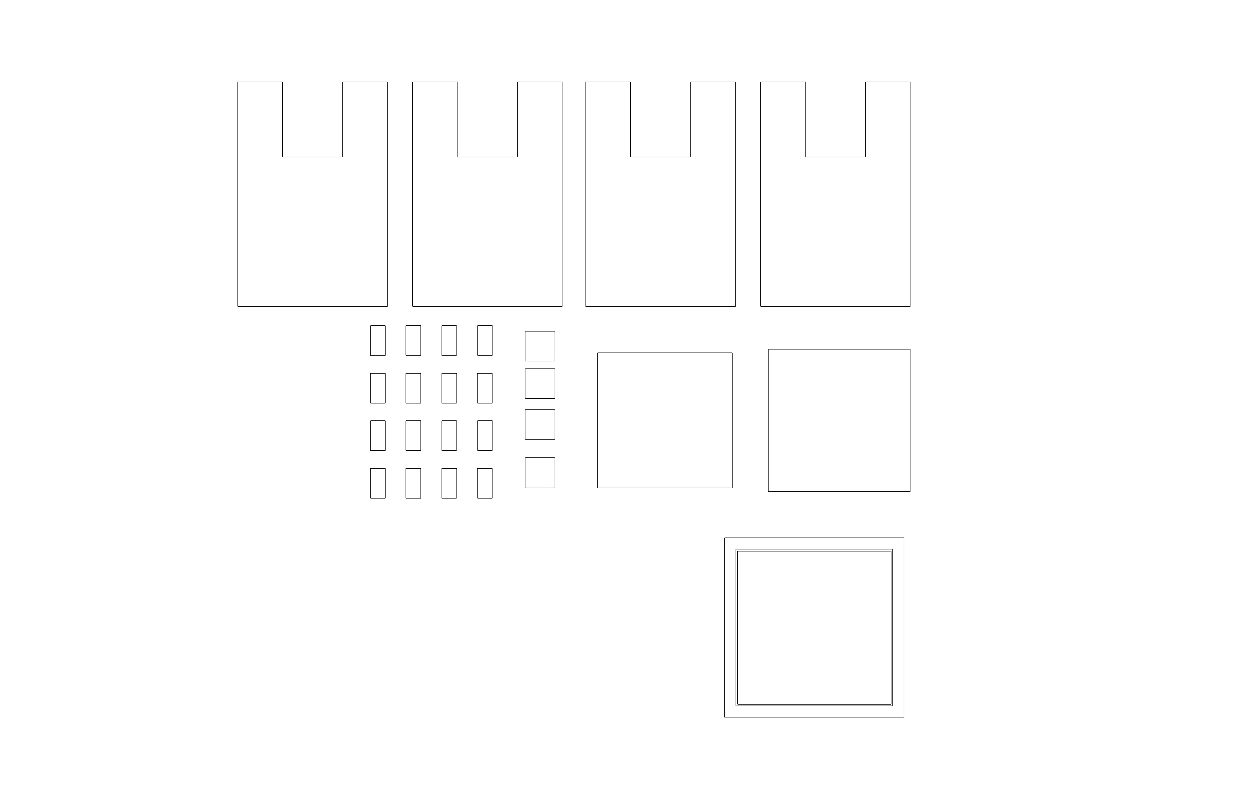
Shown above is a 2-dimensional version of the information given to the CNC mill
Narrative Sketch:
Emily is out of the house when she receives a text message from her son. He tells her that Amazon has notified him of a package delivery. She tells him not to worry, the new package collector on the porch should handle the job well.
Back home the package delivery man steps up onto Emily’s porch and places her packages into our box, which is labeled “For Deliveries: Lift Lid. Place Box” A few seconds after the package is placed and the box’s lid is closed, a mechanical “whirr” can be heard. A few hours later a school bus stops at her street corner. School student David walks off the bus and spots the new package collection box. He looks around before trying to pry it open, hoping to be rewarded with a package. Fortunately, the box resists his efforts and does not open. Defeated, David tries one last resort: picking up the box entirely and carrying it home. However he is unable to as the package collection bin is nailed to the porch floor. Already being on Emily’s property longer than he wishes, and being too afraid of getting caught continuing to poke around, David quickly leaves.
Later that day, Emily returns home and uses her key to unlock the box. She safely removes her package from within and turns the key in the lock to enable it to detect future packages.
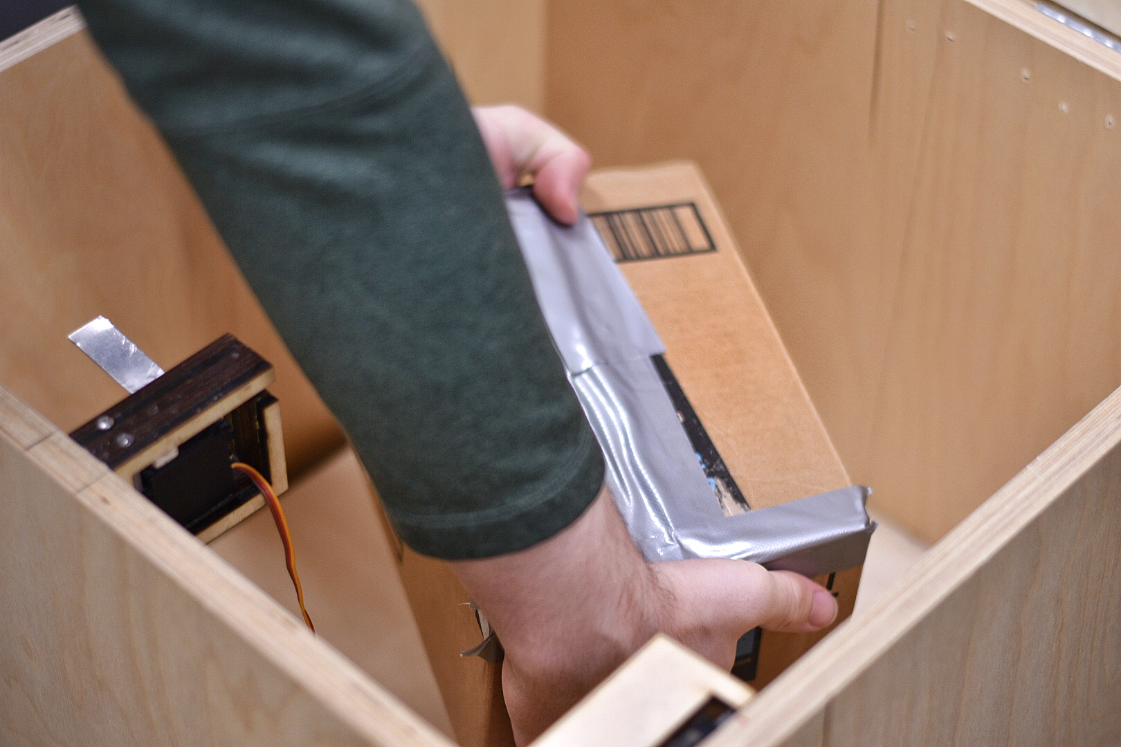
Placing a package into the box
Auto-locking feature of the box.
How We Got Here:
Staying on Track:
Our initial plan was:
Process Documentation: On all future class meetings, we will take photos, as well as the last few days.
Team Meeting: Minimum of all class days, likely on weekends
Idea Finalization: 4/15-4/17
Mechanical Planning: 4/10-4/12
Electronics Planning: 4/10-4/12
Materials Ordering: 4/10-4/14
Mechanical Fabrication: 4/15-4/23, bring to class 4/24
Electronics Fabrication: 4/17-4/22
Software Development: 4/17-4/24
Integration and Testing: 4/24-4/26
Repair/Redesign: 4/26-4/28
Presentation Prep: 4/28
Throughout the project we were mostly able to stick to our proposed plan, predominantly because we recognized the potential for things going wrong and taking much longer than expected. Thus we wanted leave ample time to confront any potential issues. However, as we started facing setbacks, we strayed from the plan as we had to merge different sections together. For instance, though we had the full structure of the box ready by April 24th, when our sensors broke (as discussed below), we had “go back” and add more structure to the box for the last working pressure sensor. This resulted in merging the repair, construction, and integration tasks together to resolve our issue.
Below we cover and reflect on our creation process from after the prototype, as our previous documentation exhibits thorough discussions on prior milestone work.
Anti-Theft Box Structure Design
Initially the mechanical fabrication seemed like a daunting task. To construct the box, we used 8′ x 4′ sheets of Baltic Birch, 3/4″ thick. The task of cutting every piece out quickly and accurately enough to make a box in the given time seemed nearly impossible. The size and thickness of the box would make typical wood shop fabrication very difficult, it would require many jigs and extra care, especially for the U-shaped cutout for the legs. So rather than cutting by hand, a CNC mill was used. The CNC mill was given a 3D model in Rhino 6 which it referenced as it cut. The entire CNC milling process took about 6 hours. From there, the pieces were pulled in a cart to the architecture wood shop. The next few days were spent sanding the faces and edges of every piece before giving it a coat of water-based polyurethane. After each coat, the wood would set for a few hours before the other side could also receive the coat. This was done 2 or 3 times for each of the 27 pieces. From there, the box was transported to the physical computing lab and hinges were attached. At first we tried only one set of hinges but found that 2 were required or else the lid rocks. After some redesigning of electrical component, a few more laser cut pieces of wood were glued inside the box to include new ideas and act as housing for various electronics.
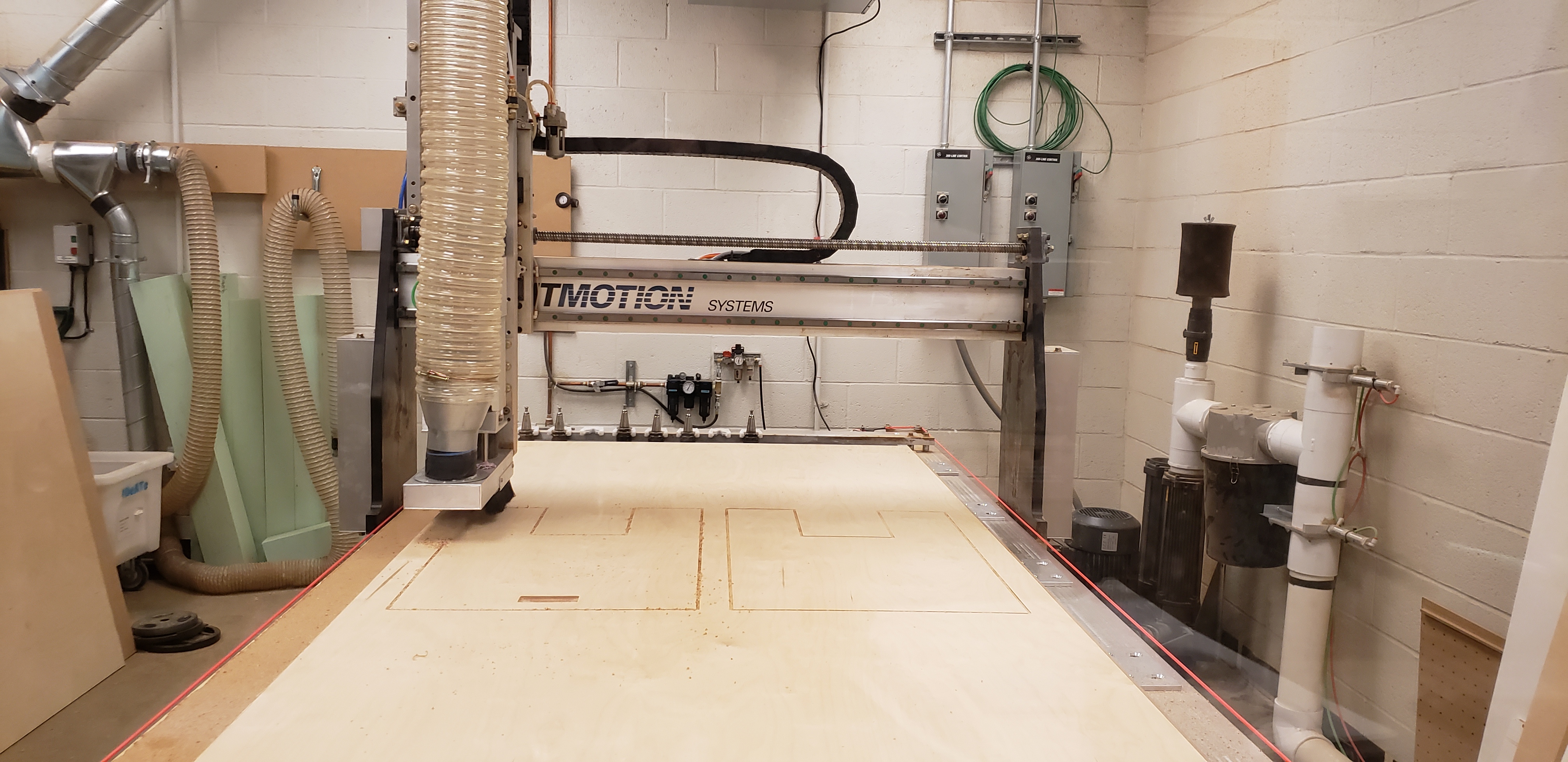
The CNC Mill cutting out the sides of the box
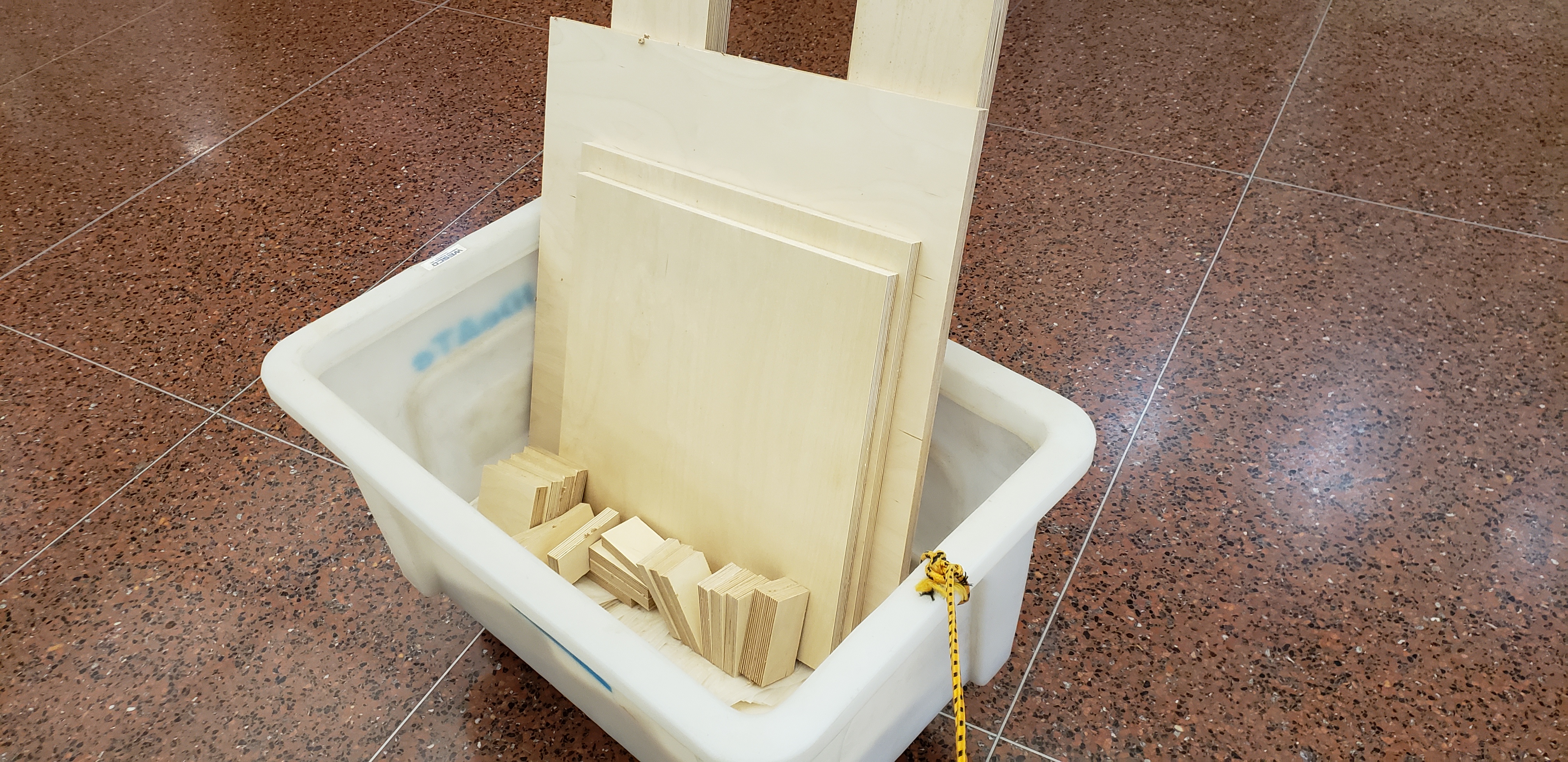
Each individual part being moved from the CNC Mill to the workshop for sanding, coating, and construction
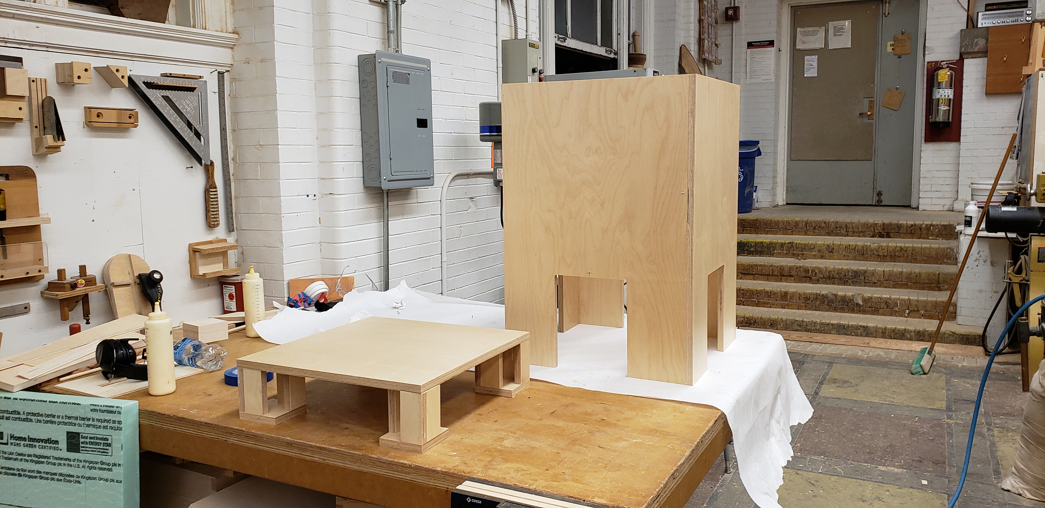
The completed box and base before they were screwed together
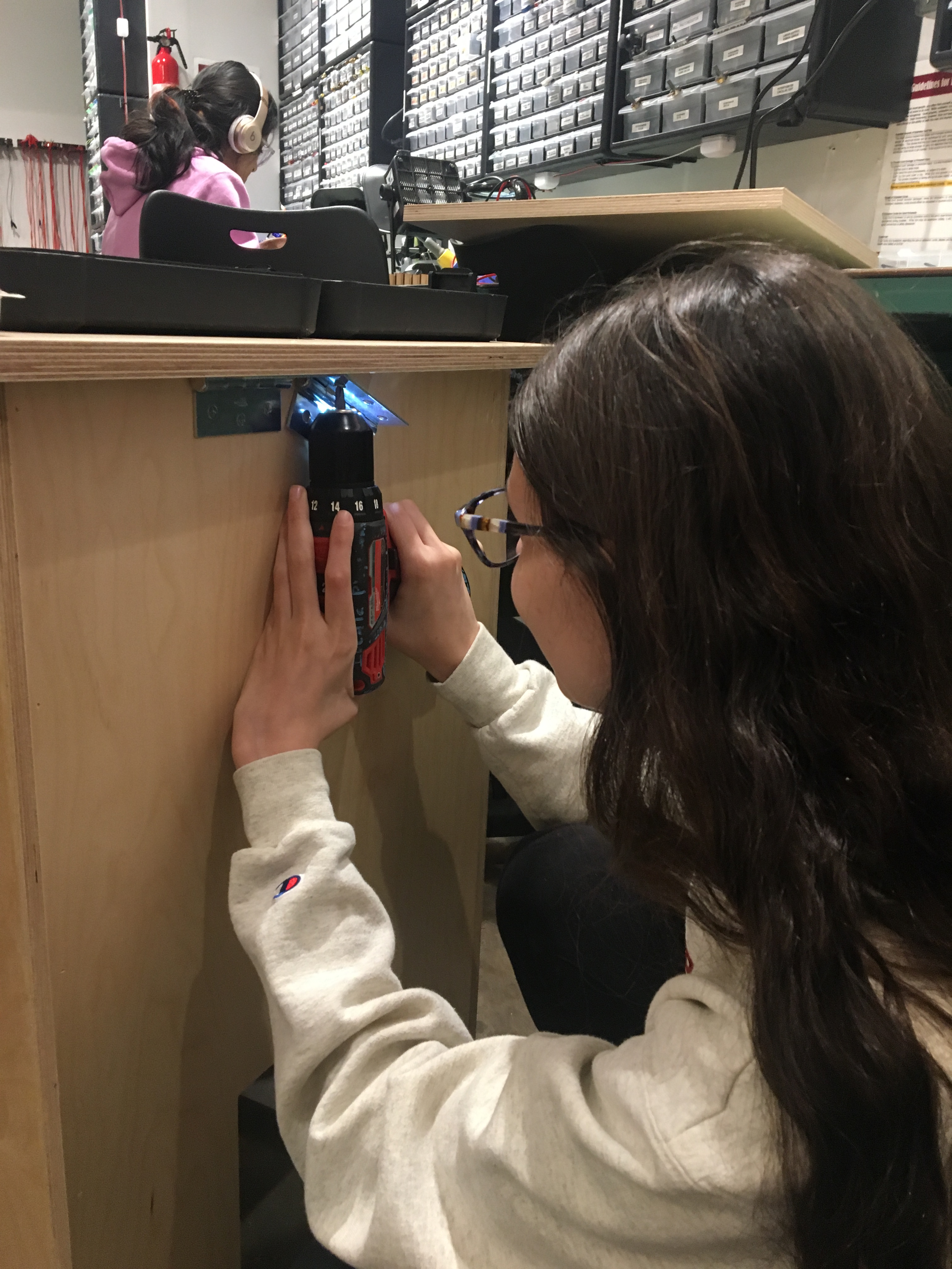
Yael screwing in the hinges to the box
Hardware Component Integration
One of the most interesting and challenging aspects of this project was designing our box’s hardware integration and configuration to enable it to function properly. In this section we cover three chief challenges we faced in this creation component: (i) the pressure sensing configuration, (ii) the locking mechanism, and (iii) our device powering.
Pressure Sensor Configuration
Our first challenge involved configuring our box’s pressure sensors to accurately detect package placement. Our initial prototype design utilized a single small rounded pressure sensor which was fully exposed on the base of the prototype box. As a result it could only detect packages that were placed directly over it, which was highly suboptimal for our project as we needed a reliable method to detect packages which were placed anywhere in the box (not necessarily over our sensors). Thus, we proposed a new solution as illustrated in the image below. We planned to elevate four sensors in each corner of the box (allowing us to hide the Arduino in the space below the sensors and the box’s base), and place a wooden cover which stretched the area of the box over them. This way, when a package was placed in the box, the cover would distribute pressure readings to each sensor, regardless of its location, thereby activating each.
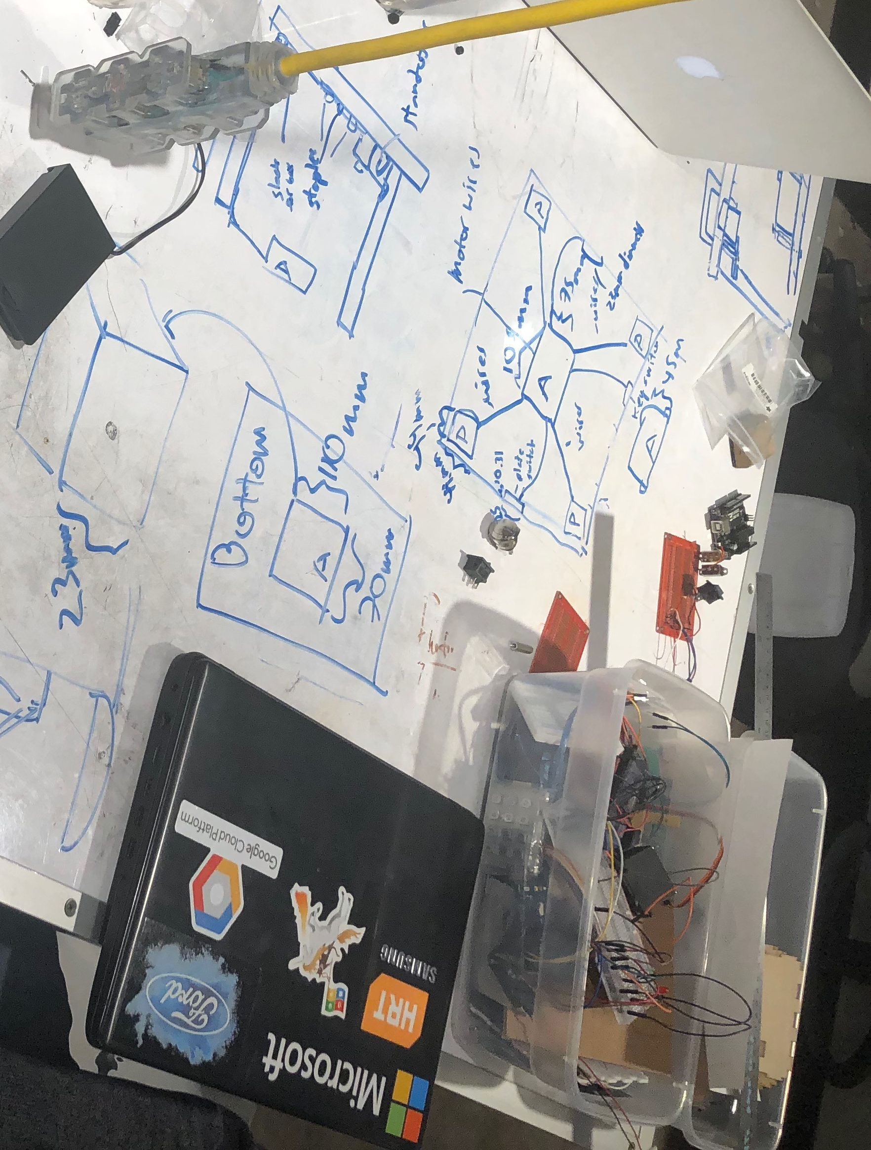
Our initial plans for pressure sensor locations in our anti-theft device. Notice the square in the center of the picture with ‘A’ and ‘P’s. The boxes with symbols ‘P’ denote pressure sensor locations, while the box with ‘A’ represents the ‘Arduino’. The blue lines emanating from the Arduino denote connection wires.
We next turned our attention to preparing the sensors for device placement by soldering wires to their wire strips. This was a challenging because their positive and negative wires were very close to one another making it very difficult to solder one end without accidentally causing a short. In order to judge our soldering success and the integrity of each resultant component, we built an example circuit which exclusively tested whether or not the sensor still worked after soldering. This allowed us to determine any potential problems with our soldering early on, before integrating each to the device.
After successfully soldering each sensor, we set about attaching them in their respective regions around the box. While there were many different ways to do this, we ultimately narrowed down our decision between tape and glue. We believed glue might be advantageous as it is much more durable, and would thus decrease the likelihood that the sensors would deviate from their initial placements. However, we were very concerned with any negative effect glue might have on the sensor’s fragile sensor wire strips and its bottom. Thus, we decided to instead use tape, which at the cost of durability, would be more flexible and thus hopefully not break the sensors. Unfortunately, we quickly found this not to be the case as four of our five sensors immediately broke after taping them to the box. Under further examination we found the underlying cause to be our bending the wire strips to snugly attach the sensors to box: bending the strips caused them break away from the main sensing component of the pressure sensor, rendering it useless. This was a significant setback, as we were now in the same position as we were in our prototype (a single sensor to detect packages anywhere). However, we persevered and quickly found a new solution: place the remaining working sensor on an elevated compartment in the center of the box, and then rest the wooden cover over it. In theory, this solution would still be effective as the cover would still react to packages being placed anywhere, which would in turn affect the sensor. We quickly built a make shift elevated compartment for the sensor, and carefully taped it to the compartment (making sure to avoid touching the wire strips). To our satisfaction, the sensor worked exactly as we had hoped.
Locking Mechanism
The second major challenge of our device creation was designing an effective locking mechanism. This could be broken down into two components: (i) the lock itself and (ii) the way in which to (un)lock it. In this section, we thoroughly discuss our approaches to each part.
Overhead shot of the package in the box, the servo wont lock since lid isn’t closed.
The Lock
The most difficult component of the lock task was designing the lock itself. In our initial prototype, we opted for motorized latch type lock, where a hobby servo motor attached to the front of the box would rotate an L-shaped latch into a slot on the lid to lock or unlock the box. However, our approach was very simple and we did not account for any weak points of contact (tugging on the box’s lid would easily break the lock). Thus, for our final product, we experimented with two different approaches: (i) using a solenoid lock (similar to a door lock), and (ii) re-designing the servo motor lock to more capably handle break-in attempts.
We were first drawn to solenoids following discussions with our professor and TA, who suggested them as a very robust and secure way to lock objects. This primarily stemmed from their metal exteriors and lock rod, as well as their metal locking slots. Furthermore, their design was such that they were naturally locked, enabling the box to remain locked in the absence of power (advantageous under situations where packages are placed inside but power has run out). Unfortunately, this same advantage was also a significant disadvantage: the only way to keep it unlocked was by constantly supplying power to it. This was highly suboptimal because a significant portion of our device usage was waiting with an unlocked lid for packages to be placed. Thus, using a solenoid would apply a significant drain our power resources during this time and substantially decrease our device’s power lifespan.
Therefore, we instead opted to pursue a re-design of our original servo motor locking mechanism. After careful consideration and discussion with our professor, we decided on a design with a single line shaped lock arm. Furthermore, to account for potential weak points of contact, we would encapsulate both the motor and the arm in a special housing to strengthen their resistance. To do this, we designed a form fitting capsule for the servo motor, which we could laser cut and stack to cover its width, before drilling screws through the wood to hold the motor in place. Such a casing would enable us to passively apply counter-pressure on every aspect of the the motor and its arm when miscreants tried to force open the box. The first figure below illustrates a single laser cut capsule, along with the complementary laser cut slot to hold the motor arm. The second showcases the stacked capsule.
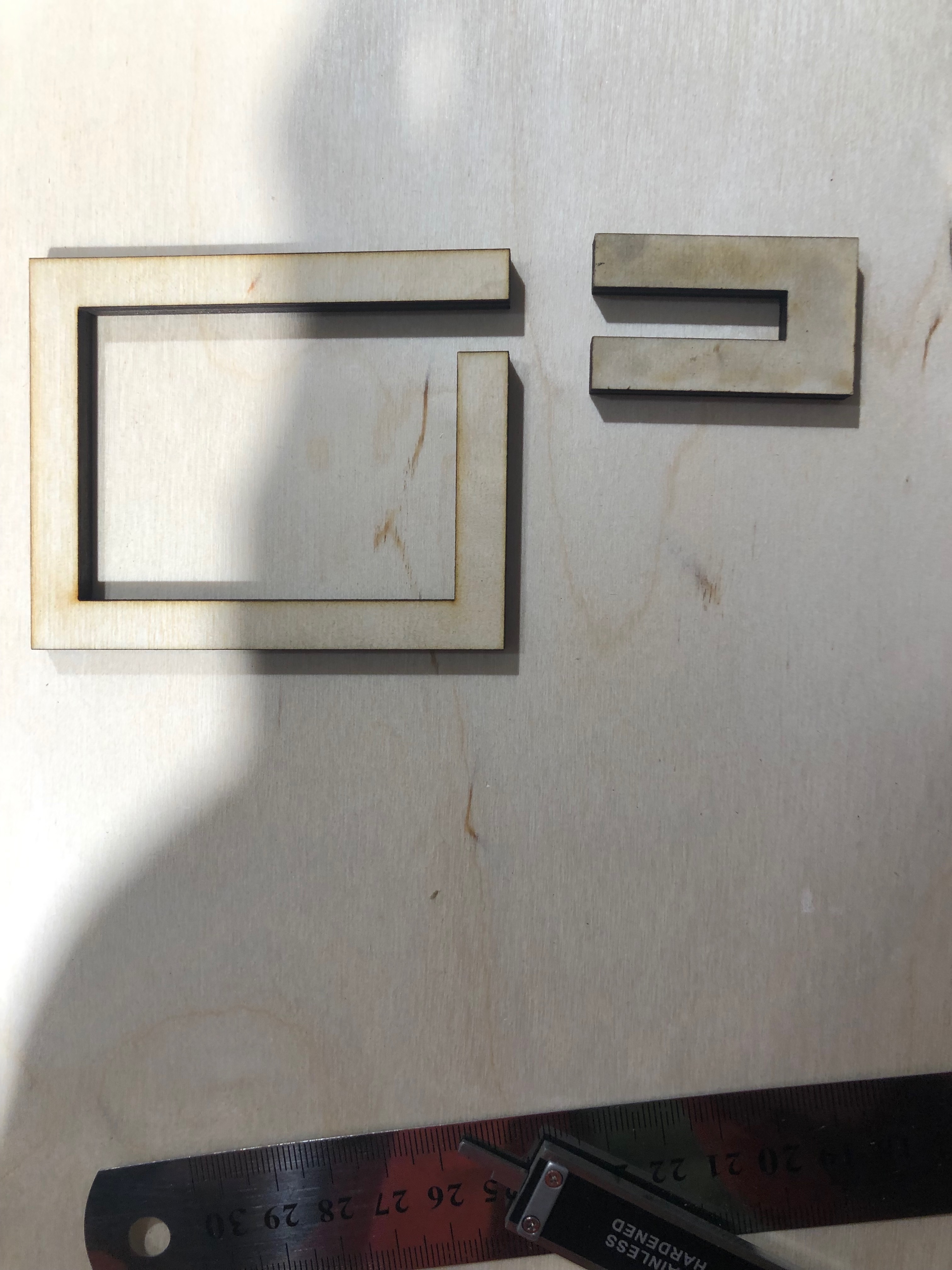
Our laser cut housing designs for the servo motor and lock arm. The left component is for the motor, with a small gap cut for the rotation of the motor arm. The right enclosing is the slot the lock arm rotates into to lock the device.
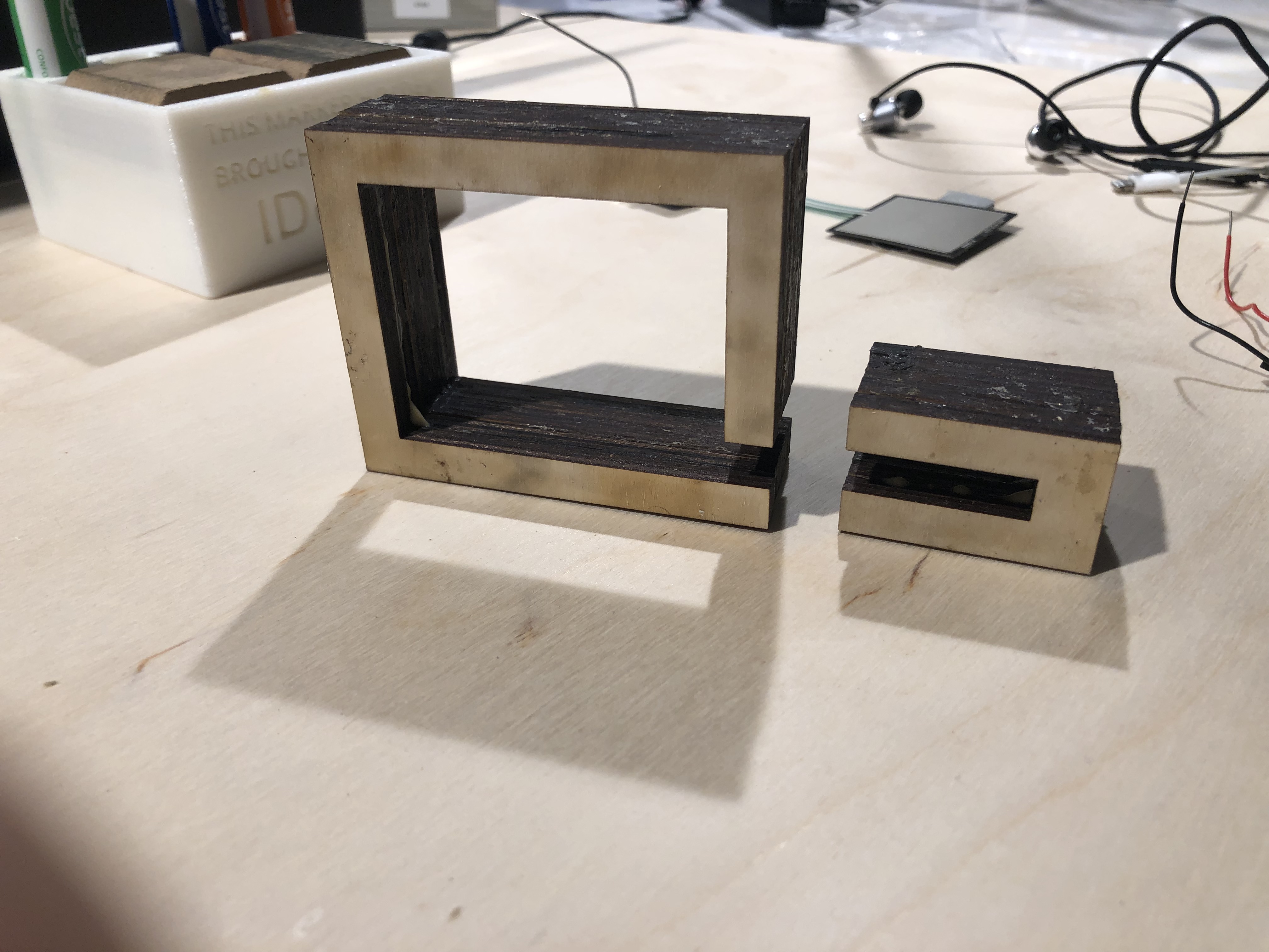
Our servo motor, left, and slot, right, housings glued together with wood glue.
Though we were able to build these housing, it was fairly challenging. None of use came from mechanical engineering backgrounds and so understanding how to create an effective encapsulation that could passively resist prying was difficult. We remember having several discussions with our professor regarding the best way to approach this before finally understanding how to design a basic solution for the problem. Moreover, securing the motor in its housing presented several additional difficulties. Our initial plan was to drill screws through four slots in the servo motor to secure it to the housing. However, we quickly realized that due to its configuration (see picture below), we could only secure it on one side, leaving the other side free. Moreover, we found inserting the screws accurately through its slots very challenging as it was difficult to measure where to insert them from the housing and further ensure that our cuts were vertical. Despite our best efforts, we accidentally broke through one of the servo motor’s slots, leaving it only secured on one of four points. Confronted with this setback, we changed our plan to filling the gap between the motor and its housing in an effort to secure it at a second point. Our final solution was fitting two wood pieces between the motor’s top and the housing, which provided a very snug and stable accommodation. The image below showcases our solution, with the fully housing attached to the box.
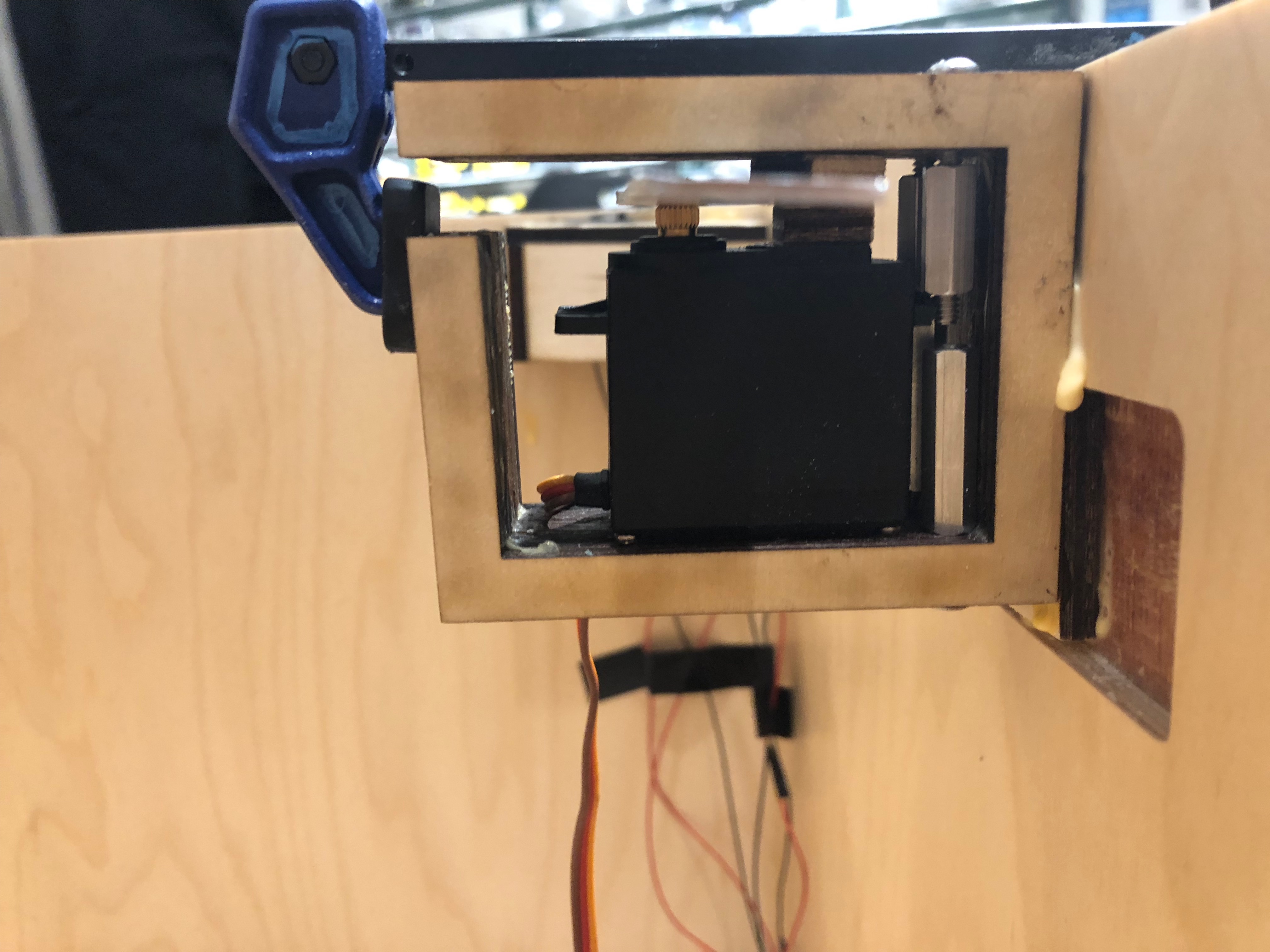
Our full lock mechanism attached to the side of the box. Notice the aluminum lock arm, the screws in the back of the motor, and wooden pieces between the housing and the motor.
Similar to the servo motor’s housing, we also laser cut and glued a specialized slot to hold the lock arm which would be placed on the box’s lid. While this task was simpler than securing the motor, it still presented a challenge in that we had to accurately measure a suitable location to glue it to the box so that the arm reached it just right: far enough from the tip of the lock arm to avoid hitting it, but close enough to ensure enough points of contact are established in case of break-in attempts. We had substantial difficulties measuring where to place the slot because we could only accurately determine a suitable location when the box was almost closed, which was inherently difficult as it meant everything was very dark. In fact, our initial slot placement, which we presented during the final critique was too far back, making the lock extremely susceptible to tugging on the lid. Thus, in the week after the final critique we laser cut new housings to extend the lock slot further to provide a much more secure lock arm fit. The image below illustrates our final solution.
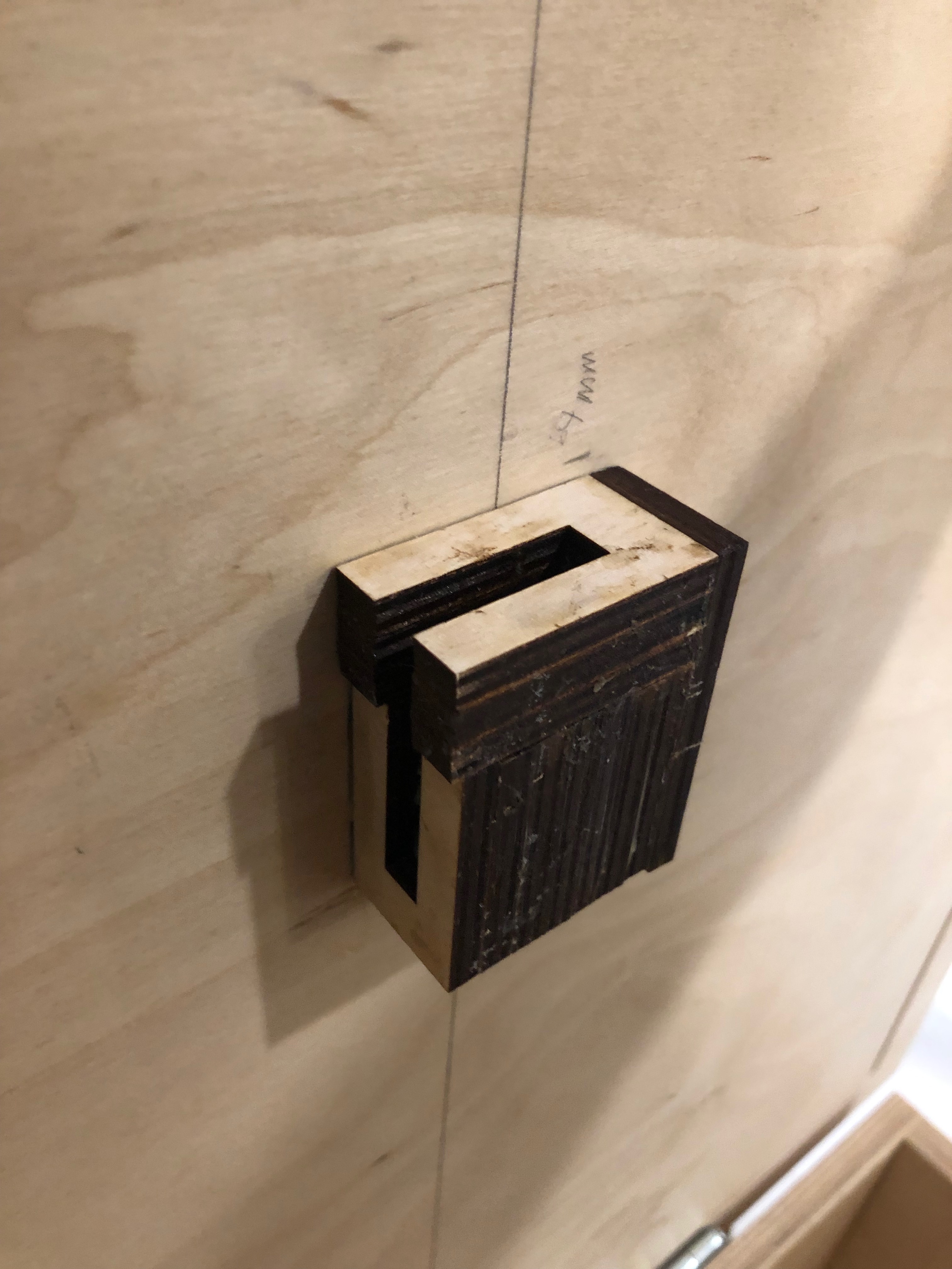
The final locking slot for the lock arm.
Lastly, we opted for what we thought was a sturdy piece of aluminum as the lock arm. While this turned out not to be the case as it could still be bent slightly from pressure, we found that adding the housing points of contact greatly diminished this problem.
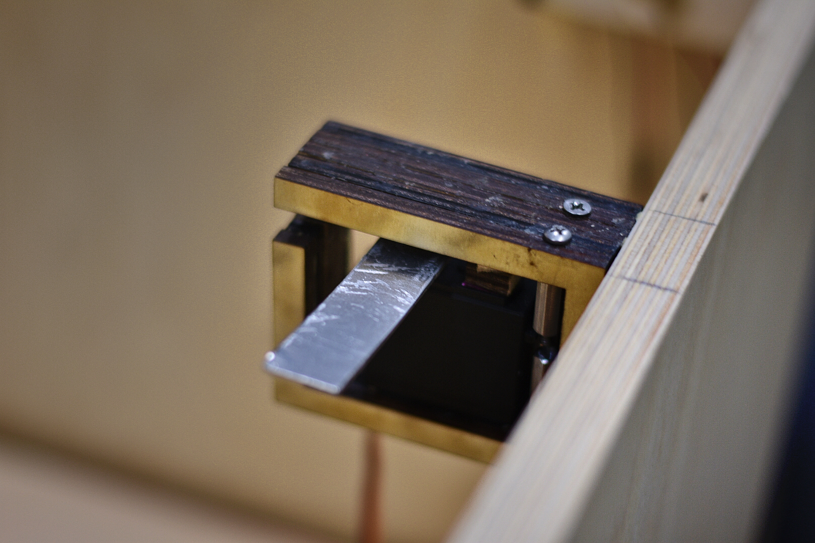
The servo lock encased in laser printed wood featuring the aluminum lock.
(Un)locking Method
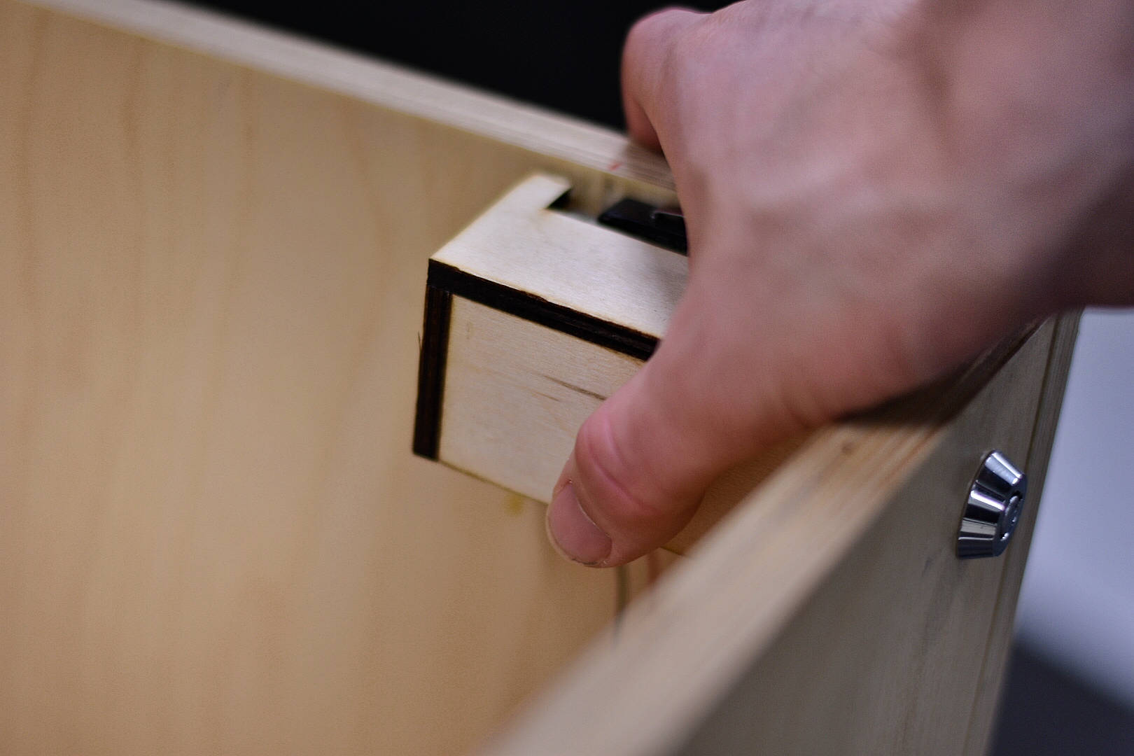
In our prototype build, we utilized a password checking system to lock and unlock the box. While in theory this approach created a heightened sense of security as the likelihood of someone guessing the correct password would be very low, it presented a couple problems. Firstly, the keypad used in the prototype was unreliable – it could not detect certain key presses. Moreover, while other keypads available to us may have been more reliable, they were necessarily weather resistant, making them not appropriate to use in our project. Secondly, keypads caused the locking to be more complicated than needed. For instance, the same objective could equivalently be accomplished with a key switch, which relied on using a correct key rather than a correct password. For these reasons, we instead opted to use a sturdy key switch locking mechanism, where Emily only needed a single correct key to operate the lock and interact with the anti-theft device. Moreover, our key switch was both weather resistant and occupied a much smaller footprint on the box than a keypad would have. We placed this switch in the top right of the box in an effort to make it easy for Emily, who is right handed.
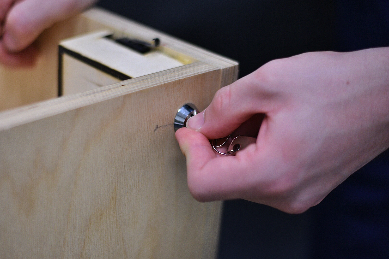
Turning the key in order to change to calibration mode or package detection mode.
Device Powering
One strong request from Emily during our prototype critique was to solar power our device instead of battery powering it (how it was powered in its prototype design). While this was a very interesting idea as it would enable us to use completely renewable energy at a relatively low cost, it was ultimately unclear how best to integrate it with her property. For instance, we collectively believed the best location to place the panel was on the top of her nearby shed. However, the solar panel’s location with respect to her house meant that it was predominately in the shade, and thus would not provide significant power.
Thus, we decided to use battery power, which was non-renewable, but much simpler to use and integrate. However, we noticed that our batteries would only last a few days on a full charge. This stemmed from the fact that our device required 40 mAh on its default state, and the batteries contained just 2800 mAh. As this discovery made battery power in its current state incredibly impractical, we met the professor to determine potential solutions. One of the first thoughts was to use stronger batteries which could hold up to 15000 mAh. However, we ultimately found these to also be impractical as they cost $100 for four (the number we needed), and only prolonged power lifespan by two weeks. Therefore, we instead proposed to set the Arduino to be powered down most of the time, thereby minimizing energy consumption, and only waking up every now and then to check whether packages exist. Interestingly, however, we found even this solution was impractical as every power down code library we tried could only reduce the energy consumption to between 25 – 30 mAh, which only extended battery life to a about five days on normal AA alkaline batteries. This was far from the battery life we hoped to achieve, which was on the order of months. Unfortunately, we have not been able to find a suitable solution to this problem (our professor wanted to discuss solutions with Emily), and thus we leave future exploration in this task to future work.
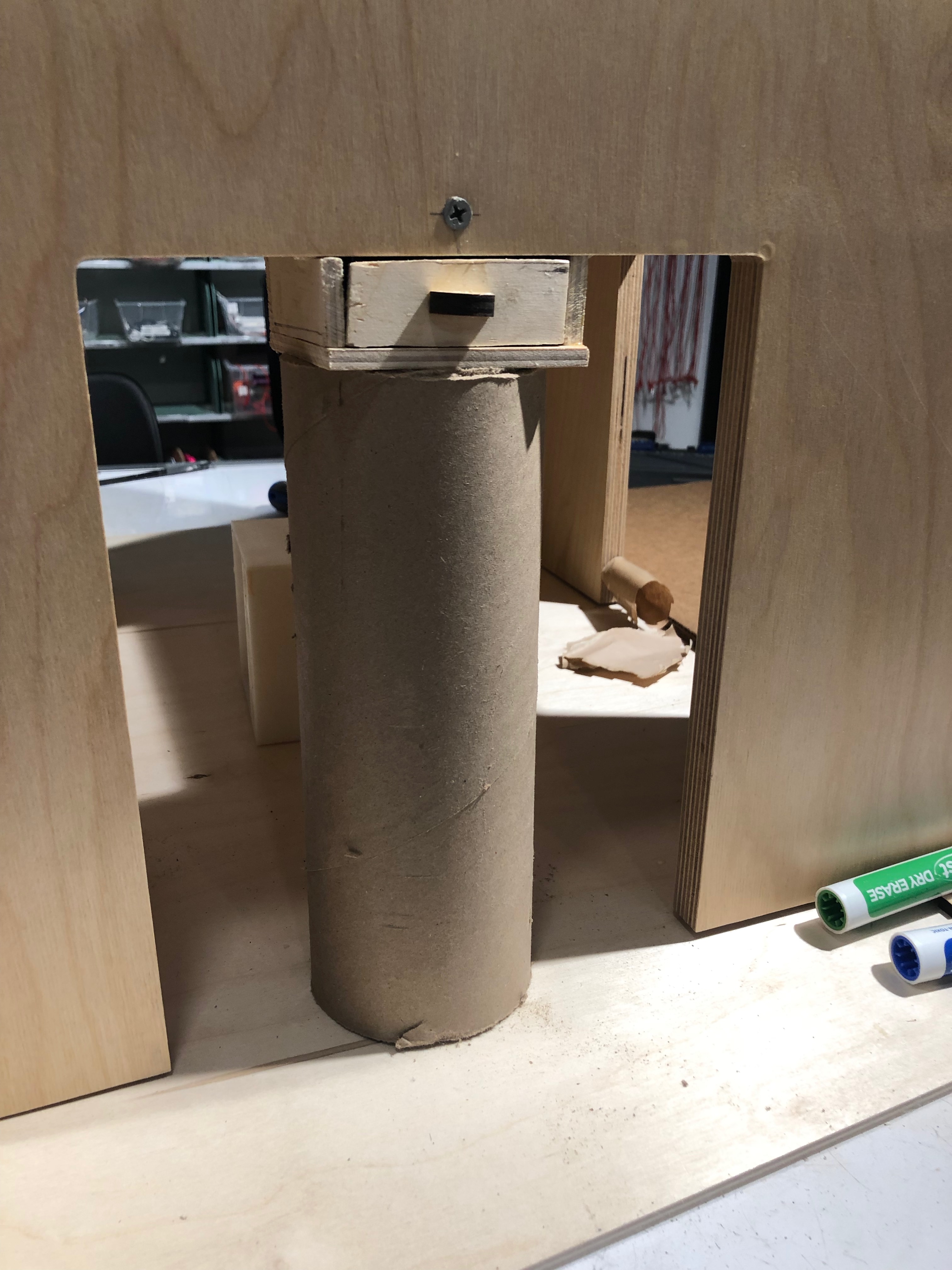
Our battery housing freshly glued to the bottom of our device. Notice the handle protruding from the front panel, allowing the users to easily open and replace dead batteries. The cardboard cylinder was used as a makeshift clasp to make sure the glue stuck between the housing and box.
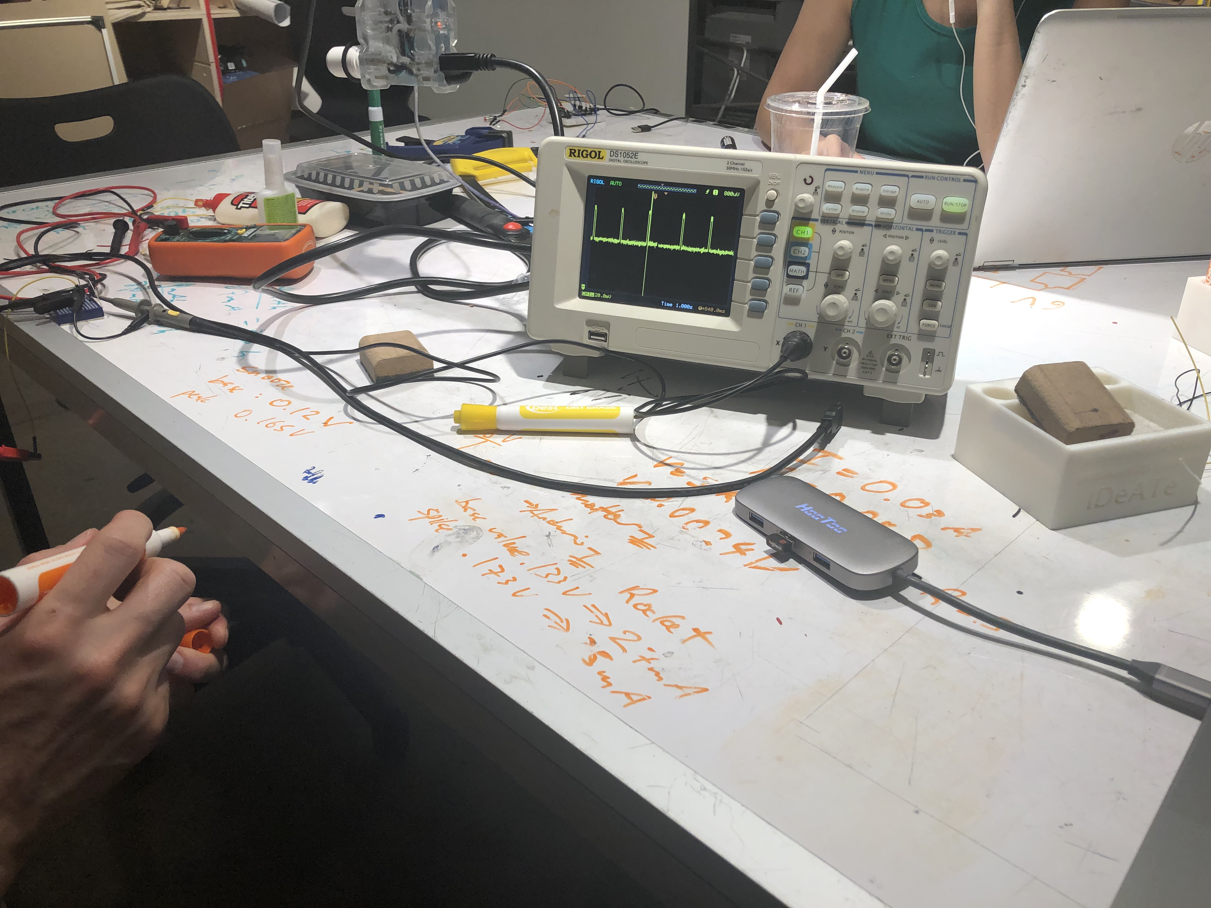
Our professor and us using an oscilloscope to measure the voltage difference between a shunt resistor. This helped us determine the default state energy consumption of our device with and without powering down.
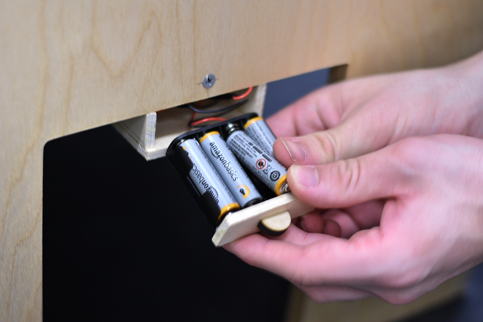
Using the sliding drawer to replace batteries.
Other hardware components
In addition to the components discussed in the above sections, we also implemented a pressure sensor reset button. In our discussions with our professor and TA, we recognized that over time the pressure sensors could deviate from their initial readings as the sensors deteriorate. Thus, we added a simple button which allows the device’s own to tare the pressure sensors on demand and recalibrate their sensing. This ensures the device can accurately determine when packages have been placed. We note, that users can only tar the device once its been unlocked (indicating the owner is present) to ensure no unwanted resetting is performed. In addition, we also added a roller arm switch which serves to detect whether the box lid is closed or open. With this, the device is able to recognize when the lid is closed, and only then locks the box if there exists a package. This prevents the dangerous scenario where the motor arm locks while the lid is still open, which prevents it from closing properly and thus becomes very susceptible to package theft.
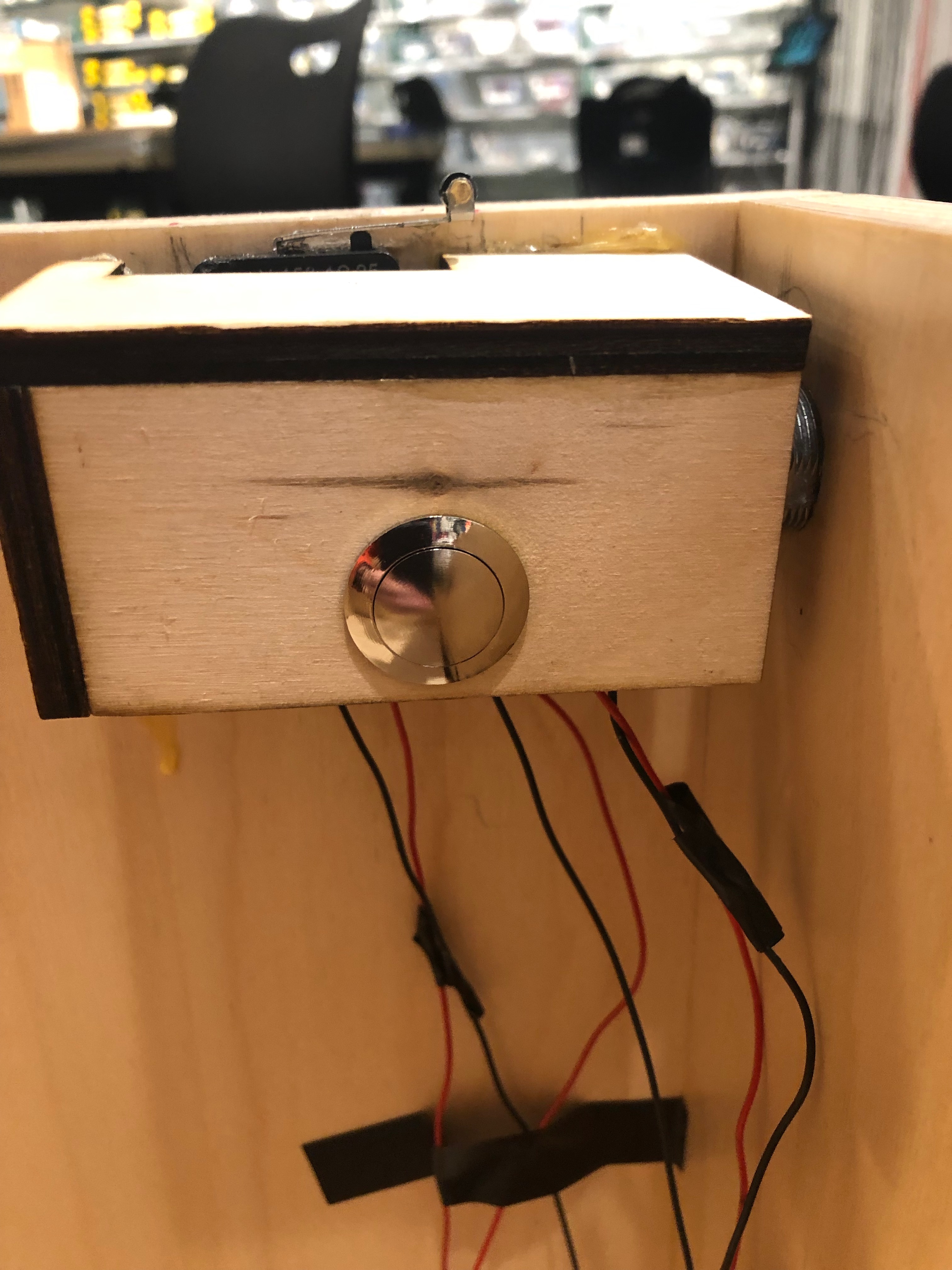
Our pressure sensor recalibration button, and roller arm switch components in the interior of the box.
Pressing the sampling button as a taring function
Software Integration
Completing our final project required significant restructuring of our code. In this section we cover each component which lead to substantial changes. Additionally, please refer to the bottom section where we embedded our final code for additional explanation and illustration for what we discuss below.
Our most significant code alteration and implementation detail was implementing the package detection logic. In our prototype, we proposed a solution which simply judged if a package was placed based on the most recent pressure reading. Unfortunately, this made our detection highly susceptible to false positives (the device detects a box when in fact it does not exist) due to occasional erratic pressure readings. This is very suboptimal for our task as the device might lock before a package is present. Thus, we instead formulated a different detection metric based on readings over a certain amount of time. Our motivation behind this was: (i) knowing readings over a past timespan can give us a better understanding of whether or not a package exists, and (ii) by conditioning on past history we substantially decrease the likelihood of false positives. The latter we believed to be true because abnormal pressure readings occurred infrequently in our experiments, making it very unlikely that these irregularities would dominate our recorded history. Therefore, we chose to record the ten most recent pressure readings, and continuously update them through each code cycle. Then, determining whether a package had been placed simply entailed checking to see that enough readings from our past history were above a certain package detection threshold. We note that though this detection metric based on history may seem relatively elementary, it worked remarkably well for our use case.
The second most impactful code implementation was our pressure sensor recalibration. As discussed in the previous section, a notable drawback from our pressure sensors was that over time their readings may stray from their original ones. This meant that the sensor could read different values under the same conditions, based on how much use it had seen. This observation immediately raised the concern of heightened false positives or false negatives (a package is placed but the device does not detect it and remains unlocked) as time went on. Indeed, the readings could increase or decrease allowing each of these to occur. For instance, the default readings could increase past the threshold and thus generate false positives, or conversely they could decrease significantly below the threshold such that even with a package on they lie below it and thus create false negatives: the aggregate reading would lie below the detection threshold and the device would remain unlocked. In our attempt to solve this issue, we proposed adding a push button, which allows the user to dynamically change the package detection threshold so that it is inline with the default readings of the sensors, and therefore minimize the likelihood of false negatives or positives. Our solution leverages our pressure reading history when calculating new thresholds, and further adds a small epsilon to account for abnormal pressure readings.
Our third change involved restructuring the device state settings. Initially we proposed to use a keypad password check to distinguish between Emily and miscreants but after discussing with her and our professor we realized that solutions could be significantly easier. For instance, we could replace the keypad – which was not weather resistant or reliable – with a key switch that was both reliable and weather resistant This was our proposed solution, and the code was very straightforward as it was simply switch logic. Similarly, our roller arm switch discussed in the previous section was very simple to implement as it was also just switch logic. The code embedded below exhibits our integration of each.
Conclusion and Lessons Learned
Final Critique Feedback
One of the biggest issues raised from our written feedback and discussions during the final critique was that our device cannot handle multiple package deliveries. For instance the question ‘what about multiple packages in a day?’ was asked more than once. While this is a true and important issue, we intentionally designed our anti-theft device to only handle single time package deliveries chiefly because Emily only expects a single delivery on any given day. Thus, as our primary goal is to create a product that is specific to Emily’s needs, we focused on single delivery anti-theft device solutions. However, scaling our approach to multi-delivery days would be an interesting task. The immediate challenge would be designing a lock which could discriminate between a package handler and Emily, and a miscreant, so that it only unlocks when package handlers or Emily are around. For such cases, it may be useful to utilize a passcode check as the discriminator.
Another important point regarded our lid closing system. Specifically, there was ‘concern [the] lid could slam down’ on the device top and damage it. This was a valid concern, and one which we had thought about in our initial product design, but ultimately did not have enough time to incorporate. However, we recognize that hardware which could solve this issue exists in our lab. Thus this would be very viable point to attend to in future work, and furthermore potentially improve the longevity of our device as it would become less susceptible to slamming damage.
A third critique discussed was that the current ‘lock might need to be stronger’ because ‘a thief could easily break open the box’. While this is partially true as although we apply substantial points of contact along the entire locking arm and motor to counteract malicious prying, it can only withstand a certain amount of pressure. We do note however, that our system satisfied the standards presented by Emily the crimes we collaboratively focused on solving were those of opportunity. In these cases, it is unlikely that potential thieves would dedicate a significant amount of time to prying open locked objects. Nonetheless, there is definitely room to improve our locks to resist more dedicated thieves. One possible solution might be to convert our servo motor to a linear actuator by transforming its rotational motion to linear motion. This would enable us to emulate the strengths door lock solenoids, which are robust to break-in attempts.
Working with Emily was such a privilege. She was extremely knowledgeable in regards to a lot of the fabrication process as well as the human-machine interaction. Emily eagerly worked with us and had a clear understanding of the difficulties of different aspects of the project. She was also very transparent the entire time, she was not afraid to tell us what she wanted and if she thought we were headed the right direction. During our prototype critique meeting, she gave a lot of constructive feedback that was extremely helpful for developing the final model. Emily’s background made her a very easy partner to work with and we all really enjoyed doing this for her. We hope the project serves her needs well.
This project served as great tool for learning the complexities of tackling real life and impactful projects. Throughout our creation and design process we faced many challenges and setbacks, which illustrated the unexpected difficulties of different processes. Looking back, we dedicated a significant amount of time to creating our solution and are satisfied with the final result. However, there are many things we would have done differently had we know about possible related difficulties in the future. For instance, had we known about the fragility about the pressure sensors, we might have opted to either purchase better quality and more expensive ones, or change our sensing direction to break beam sensing (which we had greater success with in previous projects). Secondly, had we known about the extremely impractical energy consumption of our device, we would have opted for a more energy efficient Arduino chip over the Arduino uno. Overall however, we do not regret the mistakes we made or challenges faced throughout the project as we would not learned as much about the different parts required to put together a fully functioning product.
Technical Details
Code
/*
* Title: Package Thief Prevention Box
*
* Code Function Overview:
* This code provides the functionality for our anti-theft prevention box. The comments below
* illustrate the function and use of each code element, but a summary explanations is the
* following. At the highest level, our code keeps track of the past ten pressure readings
* our pressure sensor (fsr) recorded. This history is infinitly updated through each
* iteration loop cycle. With this frame, the device lies in one of two states, determined by
* the orientation of the key switch pin.
*
* When the switch is 'locked' (HIGH), the box is in 'package detection mode' and greadily
* searches for potential packages. Once a potential package has been detected, the device
* checks its history to determine whether the reading was a fluke or an actual package and
* locks accordingly. Note however that the device will only lock if it has not already been
* locked, a package exists, and the lid is closed. Conversely, if a package is not detected,
* then the box stays unlocked.
*
* When the key switch is 'unlocked' (LOW), the device is in 'package removal and configuration
* mode'. In this state, the device unlocks (if it is currently locked), which enables the user
* to lift packages out of it. Furthermore, this mode also allows the user to recalibrate the
* sensor via taring, by pressing the sample pin.
*
* Inputs:
* - Pressure sensor
* - Key switch
* - Sample button for taer recalibration
* - Roller switch for lid closing detection
* Outputs:
* - Motor arm locking or unlocking
*
* Credit:
* We use the Adafruit SleepyDog package to power down our arduino for power savings. The
* code can be reached following this link: https://github.com/adafruit/Adafruit_SleepyDog
*
*/
#include <Adafruit_SleepyDog.h>
#include <Servo.h>
// Record pressure pin
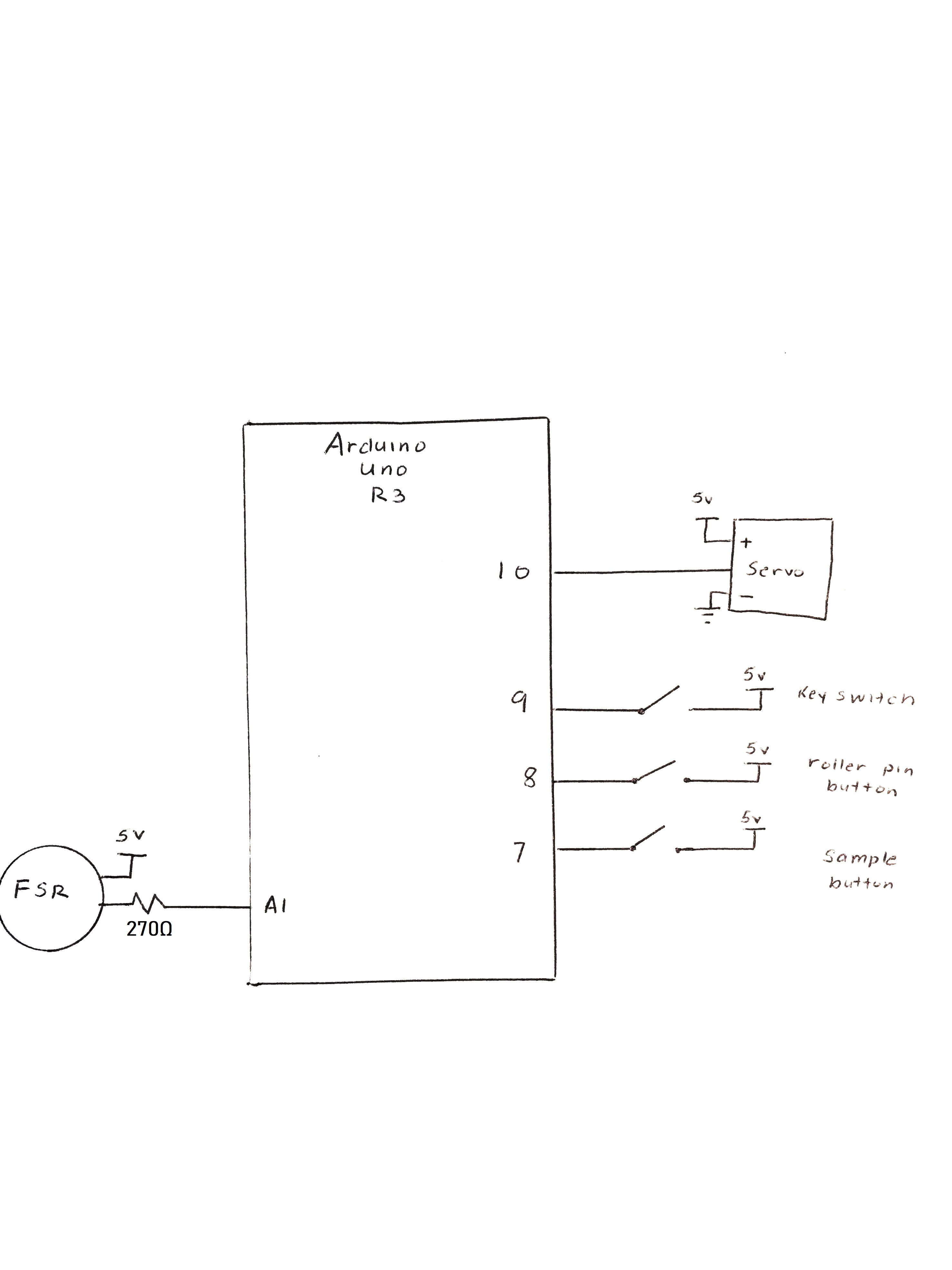
const int PRESSURE_PIN = A1;
// Record Servo Pin
const int SERVO_PIN = 10;
// Record Key Switch Pin
const int KEY_PIN = 9;
// Record Roller Switch Pin
const int ROLLER_PIN = 8;
// Record Sample Button Pin
const int SAMPLE_PIN = 7;
// Initialize MOTOR
Servo MOTOR;
// Initialize device state variables
// Record whether a package is place in the bin
bool PACKAGE_EXISTS = false;
// Record if the lid is closed
bool LID_IS_CLOSED = false;
// Record if the bin is locked
bool BIN_IS_LOCKED = false;
// Record the state of the key switch.
// Note:
// - HIGH: Key in the 'lock' position
// - LOW: Key in the 'unlock' position
int KEY_LOCKED = HIGH;
// Record whether to take a sample of pressure sensors.
// This is used to set a new threshold for package detection.
// - HIGH: Do not take sample
// - LOW: Take sample
int TAKE_SAMPLE = HIGH;
// Instantiate initial thresholds
// Unsigned to: (i) Increase INT_MAX, (ii) pressure should never be < 0
unsigned int PRESSURE_THRESHOLD = 0;
// Amount of history to record
unsigned int HISTORY_AMOUNT = 10;
// Initialize pressure history sequence
unsigned int PRESSURE_AMOUNTS[10] = {0, 0, 0, 0, 0, 0, 0, 0, 0, 0};
// Record current iteration in the device state. Also is used to update pressure amounts list
unsigned int ITERATION_NUM = 0;
// Hyper parameter indicating minimum proportion of times the pressure reading is above the
// pressure threshold for a package to be deemed to exist.
float PROPORTION_THRESHOLD = .7;
void setup() {
// Dictate Modes of all buttons, MOTORs, and switches
MOTOR.attach(SERVO_PIN);
pinMode(ROLLER_PIN, INPUT_PULLUP);
pinMode(KEY_PIN, INPUT_PULLUP);
pinMode(SAMPLE_PIN, INPUT_PULLUP);
MOTOR.write(110);
// Explicitly write arduino LED pin to LOW to conserve energy
pinMode(13, OUTPUT);
digitalWrite(13, LOW);
}
void loop() {
// Power arduino down for half a second to minimize energy consumption.
Watchdog.sleep(500);
// If the iteration is larger than the history amount, roll it over to the beginning.
// This allows us to continuously update the pressure history.
if (ITERATION_NUM >= HISTORY_AMOUNT) {
ITERATION_NUM = 0;
}
// Read the current pressure
unsigned int pressure_read = analogRead(PRESSURE_PIN);
// Update pressure history with current pressure reading
PRESSURE_AMOUNTS[ITERATION_NUM] = pressure_read;
// Read if lid is closed, lock is in closed position, and whether to take a sample
LID_IS_CLOSED = digitalRead(ROLLER_PIN);
KEY_LOCKED = digitalRead(KEY_PIN);
TAKE_SAMPLE = digitalRead(SAMPLE_PIN);
// Key is in the unlocked position
if (KEY_LOCKED == LOW) {
// If the box is locked, unlock it.
if (BIN_IS_LOCKED) {
// Indicate that the box is now unlocked. This ensures that we do not redundantly
// make the MOTOR unlock an already unlocked box.
BIN_IS_LOCKED = false;
// Unlock box
MOTOR.write(100);
// Delay to give MOTOR time to unlock the box
delay(1000);
}
// Take sample if desired. Assumes that the package is already outside the box.
// Note that a sample can only be taken if: (i) key is in unlocked position
// (box is unlocked), (ii) the box lid is open (gives us an indication that
// that the person has removed the package, (iii) person requests a sample to be taken.
if ((LID_IS_CLOSED == HIGH) && (TAKE_SAMPLE == LOW)) {
// Reset pressure threshold
PRESSURE_THRESHOLD = 0;
// Compute new pressure threshold. We take the max of all pressure history to
// Try and account for 'worst case' abnormal pressure readings.
for (int i = 0; i < HISTORY_AMOUNT; i++) {
PRESSURE_THRESHOLD = max(PRESSURE_THRESHOLD, PRESSURE_AMOUNTS[i]);
}
// Add a small epsilon of error to account for small variations in pressure
// readings in the packageless state.
PRESSURE_THRESHOLD+=5;
}
}
// Box is in package detection mode
else {
// Lid is not locked and a potential package has been sensed.
if (PRESSURE_AMOUNTS[ITERATION_NUM] > PRESSURE_THRESHOLD && !BIN_IS_LOCKED) {
// Look at past pressure reading history to determine whether a potential package exists.
float package_readings = 0;
for (int i = 0; i < 10; i++) {
int pressure_reading = PRESSURE_AMOUNTS[i];
// Current reading is above our threshold for determining whether potential packages exist.
if (pressure_reading > PRESSURE_THRESHOLD) {
// Record observation
package_readings++;
}
}
// Compute the average number of times a potential package has been detected
// over the past history.
package_readings = package_readings / HISTORY_AMOUNT;
// A potential package has been detected enough times to determine it is
// an actual package.
if (package_readings > PROPORTION_THRESHOLD) {
PACKAGE_EXISTS = true;
}
// A potential package has not been detected enough times to determine it
// is an actual package.
else {
PACKAGE_EXISTS = false;
}
}
// No potential package has been detected
else {
PACKAGE_EXISTS = false;
}
// Lock box if a package exists, the lid is closed, and the box is not already locked.
// Note that by tracking if a box is already locked, we eliminate redundant commands to
// to the MOTOR regarding locking the box.
if (PACKAGE_EXISTS && (LID_IS_CLOSED == LOW) && !BIN_IS_LOCKED) {
// Lock the box
MOTOR.write(35);
// Inidicate that the box is now locked
BIN_IS_LOCKED = true;
// Delay to give MOTOR enough time to lock the box
delay(1000);
}
}
// Increase iteration number to next step in history
ITERATION_NUM++;
}
Schematic and Design Files
Comments are closed.