Class log
Note: “codebook” entries below are verbatim pasting of all of the code we used in class. It’s possible they may not compile (i.e. may have errors) if we left things unresolved, or were writing pseudocode, etc.
- Monday, Jan. 13: intro
- Wednesday, Jan. 15: circuits and blinks
- Wednesday, Jan. 22: inputs
- Monday, Jan. 27th: IDeATe tour and more parts
- Wednesday, Jan. 29th: more inputs and outputs
- Monday, Feb. 3rd: Project 1 group consultations
- Wednesday, Feb. 5th: external power et al.
- Monday, Feb. 10th: project 1 work day
- Wednesday, Feb. 12th: Project 1 critique
- Monday, Feb. 17th: Fritzing, photography, and Project 2
- Wednesday, Feb. 19th: 2D CAD and lasercutting tutorial
- Monday, Feb. 24th: Non-blocking code and work day
- Wednesday, Feb. 26th: Project 2 prototypes due
- Monday, March 2nd: Project 2 work day
- Wednesday, March 4th: Project 2 due
- Wednesday, March 18th: Class virtually resumes (get it?)
- Monday, March 23rd: Introduction to final project
- Wednesday, March 25th: Check-in and interview time
- Monday, March 29th: Post-interview check-ins
- Wednesday, April 1st: Prototyping prep
- Monday, April 6th: Prototype critique
- Wednesday, April 8th: Prototype debrief and forward planning
- Monday, April 13th: Guest speaker Laura Poskin
- Wednesday, April 15th: Logic lesson and work time
- Monday, April 20th: Alternative devices and work time
- Wednesday, April 22nd: work day
- Monday, April 27th: First round of final critiques
- Wednesday, April 29th: Second round of final critiques
Monday, Jan. 13: intro
- Introduction to course content, policy, and housekeeping (with reference to the course website’s home page)
- Go around sharing names, identifiers, language clues, things people have built
- Quick overview of the Phys Comp Lab space (electronics, tools, resources, storage)
- Arduino Uno board tour (pins, components, ports, LED indicators)
- Navigating the Arduino IDE (Integrated Development Environment)
- Beginning to write our first blinking sketch
- Homework 1 assigned, due at start of class on Wednesday Jan. 15th
codebook: firstBlink
// goal: write some software to make the LED attached to pin 13 blink.

/*
basic structure:

 1. turn on the LED
 2. turn off the LED
 3. repeat
 */

 // stuff that happens only once when the Arduino starts
 void setup(){
  // tell the Arduino what "mode" every pin we're using has
  pinMode(13, OUTPUT);
 }


// stuff that happens repeately while the Arduino is running
void loop(){
  // turn on the LED
  digitalWrite(13, HIGH)

  // turn off the LED
      ;

digitalWrite(13, LOW);
}
Wednesday, Jan. 15: circuits and blinks
- Syllabus quiz and brief review
- Going over everyone’s selected sharable projects for Homework 1
- Basic circuit schematics: symbols and connections. Symbols explained:
- wire/trace
- node
- crossing wires
5Vandgnd- switch
- diode
- light emitting diode (LED)
- resistor
- Using a breadboard and jumper wires
- Using pin 13 to blink an external LED
- Homework 2 assigned
codebook: a tiny bit more blinking
(This code is just slightly different from Monday’s “firstBlink” sketch.)
// goal: write some software to make the LED attached to pin 13 blink.

/*
  basic structure:

  1. turn on the LED
  2. turn off the LED
  3. repeat
*/

// stuff that happens only once when the Arduino starts
void setup() {
  // tell the Arduino what "mode" every pin we're using has
  pinMode(13, OUTPUT);
}


// stuff that happens repeately while the Arduino is running
void loop() {
  // turn on the LED
  digitalWrite(13, HIGH);
  // do nothing for _____ milliseconds
  delay(500);

  // turn off the LED
  digitalWrite(13, LOW);
  delay(250);

    // turn on the LED
  digitalWrite(13, HIGH);
  // do nothing for _____ milliseconds
  delay(1000);

  // turn off the LED
  digitalWrite(13, LOW);
  delay(1000);
}
Wednesday, Jan. 22: inputs
- Harshine’s lab hours: Fridays 3:00–5:00 p.m.
- Updated Times/Dates as of 1/23: There are three upcoming EH&S fire safety practical training sessions on Thursday 1/30, which will be offered either in the Physical Computing Lab or in room A5 (diagonally across the hallway):
- 1:30–2:15 p.m.
- 2:15–3:00 p.m. If you can show up for one of those, you’ll be able to save yourself the trouble of attending a different training session at a different location on campus at a later date.
I = V/R, understanding that flow is a result of pressure, and solving for different variables- Using a potentiometer (wiring and breadboarding)
- Reading a potentiometer in software with
analogRead() - Homework 3 assigned
codebook: simple analogRead
// read the position of a potentiometer

/* pin mapping:
 *
 *  pin     mode     description
 *  A0      input     potentiometer
 *
 *
 */

void setup(){
  // set the pin modes appropriately
  pinMode(A0, INPUT);
  pinMode(13, OUTPUT);
  Serial.begin(9600);
}

void loop(){
  // make a new variable of type "integer"
  int pos; // the name of the variable is pos

  pos = analogRead(A0); // load the value of analogRead(A0) into pos
  Serial.println(pos);

  if (pos <= 500) { // can also test for equality, greater than, less than,
    // or inequality
    digitalWrite(13, HIGH);
  } else {
    digitalWrite(13, LOW);
  }
}
Monday, Jan. 27th: IDeATe tour and more parts
- Review of Homework 2 schematics. Some notes:
- ground should be drawn at bottom center of Arduino
5Vshould be drawn at top center- all resistors must be labeled!
- nodes need to have dots
- if possible, it’s nice to share one ground for nearby things that need it (this declutters)
- Brief introduction to the IDeATe network by our very own Kelly Delaney
- IDeATe walking tour co-led by our very own Cody Soska
- PhotoZone (photo booth at the end of the hallway)
- Media Lab
- Fabrication Lab (room A5), including lasercutters and 3D printers
- IDeATe Lending Booth
- IDeATe Wood Shop
- Soft Fabrication work space (room A31)
- Coding style notes
- Use
const intvariables withALL_CAPSnames for unchanging pin assignments - Use
int(or other type) variables withcamelCasenames for changing values
- Use
- Reading resistor color codes (using this chart or its ilk)
- And comparing them with values measured with a multimeter
- Reading a photoresistor (tutorial)
- building a voltage-divider circuit (also discussed in the tutorial)
- Assignment of Homework 4: Nightlights
codebook: simple photocell reading
// read a photocell's value and print it to the serial monitor

/*
 * pin mapping:
 *
 * pin  | mode  | description
 * -----|-------|------------
 * A3     input   photocell
 */

// make a constant variable to store the pin assignment
 const int PHOTOPIN = A3;

 void setup(){
  pinMode(PHOTOPIN, INPUT);
  Serial.begin(9600);
 }

 void loop(){
  int photoVal = analogRead(PHOTOPIN);
  Serial.println(photoVal);
  delay(50);
 }
Wednesday, Jan. 29th: more inputs and outputs
- Arduino data types (see relevant Arduino.cc reference section for details)
intstores “integers” (whole numbers) -32,768 to 32,767longstores a bigger range of integers, -2.1 billion to 2.1 billionunsigned intstores a non-negative integer, 0 to 65,535unsigned longstores a non-negativelong, 0 to 4.2 billionfloatstores a number with a decimal point in it, -3.4×10^38 to 3.4×10^38charstores a single character likea,?,Q, or8(the character8, not the number 8)Stringstores a “string,” or chain, of characters, likeHey, thereorA28DN29boolstores a boolean value, eithertrueorfalse(equivalent to 1 and 0 respectively)
- Illustrating that reversing the order of the photoresistor and fixed-value resistor in a voltage divider will result in inverted sensing voltages
- New parts introduced:
- HC-SR04 ultrasonic ranger (course tutorial)
- ADXL335 analog accelerometer (course tutorial)
- 9g size hobby servo motor (course tutorial)
- Project 1 introduced and teams announced (see Canvas site announcement for team details)
codebook: very-lightly modified NewPing example (for use with HC-SR04 ultrasonic ranger)
// ---------------------------------------------------------------------------
// Example NewPing library sketch that does a ping about 20 times per second.
// ---------------------------------------------------------------------------

#include <NewPing.h>

#define TRIGGER_PIN  12  // Arduino pin tied to trigger pin on the ultrasonic sensor.
#define ECHO_PIN     11  // Arduino pin tied to echo pin on the ultrasonic sensor.
#define MAX_DISTANCE 200
/* Maximum distance we want to ping for (in centimeters).
Maximum sensor distance is rated at 400-500cm. */

NewPing sonar(TRIGGER_PIN, ECHO_PIN, MAX_DISTANCE); // NewPing setup of pins and maximum distance.

void setup() {
  Serial.begin(115200); // Open serial monitor at 115200 baud to see ping results.
}

void loop() {
  /* Wait 50ms between pings (about 20 pings/sec). 29ms should be the shortest delay between pings. */
  delay(50);
//  Serial.print("Ping: ");
  Serial.println(sonar.ping_cm());
  /* Send ping, get distance in cm and print result
  (0 = outside set distance range) */
//  Serial.println("cm");
}
codebook: printing analog accelerometer values to the serial display
// read the three axes of an analog accelerometer

const int XPIN = A0;
const int YPIN = A1;
const int ZPIN = A2;
const int LEDPIN = 8;

void setup(){
  pinMode(XPIN, INPUT);
  pinMode(YPIN, INPUT);
  pinMode(ZPIN, INPUT);
  pinMode(LEDPIN, OUTPUT);
  Serial.begin(9600);
}

void loop(){
  if (analogRead(XPIN) > 500){
    digitalWrite(LEDPIN, HIGH);
  }
  Serial.print(analogRead(XPIN));
  Serial.print(",");
  Serial.print(analogRead(YPIN));
  Serial.print(",");
  Serial.println(analogRead(ZPIN));
}
codebook: simple hobby servo start
#include <Servo.h>

const int MOTORPIN = 5;

Servo steeringMotor; // create a motor "object" called steeringMotor

void setup(){
  steeringMotor.attach(MOTORPIN);
}

void loop(){
  // move the motor to ___º position (0–180 range)
  steeringMotor.write(5); // go to 5º
  delay(500);
  steeringMotor.write(80); // go to 80º
  delay(500);
}
Monday, Feb. 3rd: Project 1 group consultations
- Note of commiseration and solidarity regarding the coronavirus epidemic. Our thoughts go out to those who have been affected and their friends and loved ones. Please get plenty of rest, drink fluids, and wash your hands!
- How to use the Physical Computing Inventory to search for parts and report missing/low-stock items
- Using
analogWrite()to fake output voltages between 0V and 5V. - Project 1 team meetings
codebook: code layout
This code obviously won’t compile, and is just meant to serve as an example of the sort of overall generic structure that is applicable to many Arduino projects.
const int PINASSIGNMENT = 3;

void setup() {
  pinMode(blah blah blah
}

void loop() {
  bool lightState = false;

  //  1. read information from the world
  int photoVal = analogRead(PHOTOCELL);

  //  2. do your processing on that information
  if (photoVal > 500) {
    lightState = true;
  } else {
    lightState = false;
  }

  //3. make changes in your outputs
  digitalWrite(LEDPIN, lightState);


  //4. report back to the user (as needed)
  Serial.println((String) "lightState: " + lightState +
                 "photoVal: " + photoVal);
}
Wednesday, Feb. 5th: external power et al.
- Basics of using external power to run things attached to the Arduino (needed for devices that run on 5V but need more current than the Arduino can supply, on devices that run on a voltage other than 5V)
- Never connect a non-5V supply to the Arduino’s 5V pin
- Build a transistor circuit so the Arduino switches power from an external source (for example, use a ULN2803, or IRF540N)
- Power the Arduino by applying an external 5V supply to the Arduino’s 5V pin
- Power the Arduino by plugging an external 7–12V to the DC input barrel jack
- Power the Arduino by plugging an external 7–12V to the VIN pin (but never the 5V pin)
- Basic multimeter use: continuity mode, ohmmeter, voltmeter
- Please note: Project 1 has slightly expanded requirements (an LCD status display, as well as a clarified labeling requirement)
- Students who will need to produce varying volume: use the library called
Volume 3, which allows for volume variation - Students who will need to measure varying volume: use the “Sparkfun Sound Detector” module, which you can borrow from IDeATe Lending; its “envelope” output pin will give a reasonable approximation of volume
- Work day for Project 1
codebook: mapping values from one range to another
A very brief explanation of the map() function; see the relevant reference page for further detail and explanation.
// how to change one number range into another range???

/*
 * turn: 0-1023 into 0-99
 *
 * turn: 300–800 into 0-99
 *
 */

 map(input value, input range min, input range max, output range min, output r. max);

 //turn: 300–800 into 0-99

 rerangedVal = map(inVal, 300, 800, 0, 99)
Monday, Feb. 10th: project 1 work day
- Quick tech note: how to achieve periodic updating of the LCD screen without blocking the rest of the code from running as quickly as needed (see clode samples below)
- Project 1 work day
codebook: periodic updating
/*
   sample code: running a periodic non-blocking task

   (useful for Project 1 LCD display output)
*/

int counter = 0; // variable to use for periodic updates
const int FREQ = 500; // number of loop()s to run before update

void setup() {
}

void loop() {
  // update input(s)
  // compute state(s)
  // update output(s)

  if (counter >= FREQ) { // if counter meets or exceeds FREQ
    // run LCD screen update procedure here
    counter = 0; // and reset counter
  }
  counter++; // increment counter every loop cycle
}
codebook: timer-based periodic updating
/*
   sample code: periodic updating with explicit timer

   (useful for Project 1 LCD display output)
*/

unsigned long timer = 0; // variable for timing
const int INTERVAL = 500; // milliseconds between updates

void setup() {
}

void loop() {
  // update input(s)
  // compute state(s)
  // update output(s)

  if (millis() >= timer){
    // run LCD screen update procedure here
    timer = millis() + INTERVAL; // and update timer
  }
}
Wednesday, Feb. 12th: Project 1 critique
Critique schedule:
| time | activity |
|---|---|
| 9:30–35 | frenzied fixing |
| 9:35–10:50 | team presentations |
| 10:50–11:10 | signal chain prep |
| 11:10–11:20 | signal chain attempts |
Monday, Feb. 17th: Fritzing, photography, and Project 2
- Quick debrief of Project 1 critique
- Fritzing:
freeand open-source schematic-drawing software- Apparently not free any more! Oops. To download for free, see link posted to course site.
- Adding components to the schematic view
- Adding VCC and ground
- Modifying component labels
- Hiding and showing
- Changing labeled values using the Part Inspector (bottom right corner)
- Rotating components and labels
- Adding “custom” parts using the generic IC component
- Brief review of the “breadboard” view
- Exporting a schematic to an image
- Project 2 introduced
- General motivation: make an assistive device for yourself
- Prior works as exemplars
- First assignment section, Brainstorming, is due by appointment on Friday 2/21. See course Canvas page for link to sign-up sheet.
- DSLR (digtal single-lens reflex) photography primer
- Lesson with reference to the course DSLR tutorial page
- Brief hands-on lesson using cameras to photograph things in the IDeATe PhotoZone
Wednesday, Feb. 19th: 2D CAD and lasercutting tutorial
- In-class tutorial on using Fusion 360 for 2D design work
- Make a new file
- Create a rectangle of specified dimensions (25mm x 50mm)
- Use Fillet tool to round a corner
- Adjust Fillet radius
- Use Line tool to draw points on the existing rectangle edge and connect them to create a new triangle corner chord
- Use Trim tool to eliminate extra lines and complete corner cut
- Use a digital caliper to dimension a part
- Zero before measuring
- Select units of interest
- Clamp around desired part or element, using thumb wheel to advance movement
- Return to Fusion
- Use measured dimensions to create cutout appropriately dimensioned for desired mounting
- Exit the sketch
- Extrude the sketch 3mm (since we’re cutting 3mm wood in this tutorial)
- Create a new sketch on the top surface of the extruded part
- Add text: your Andrew ID
- Explode that text to make it lasercuttable (this will be laser scored)
- Add a polygon somewhere on the sketch (this will be laser etched)
- Right click the sketch name in the design tree in the left column, and select Save As DXF to export it for lasercutting
- Cody teaches how to use RDWorks for driving our laser cutters
- All students take turns on the lasers cutting out their parts
Monday, Feb. 24th: Non-blocking code and work day
- How to write non-blocking code: use
millis()and a timer to test if it’s been long enough to run a routine that needs running- The code we wrote in class was lost when the Arduino software unexpectedly quit; see the relevant tutorial page for everything you need to know.
- Brief discussion/clarification of expectations for Project 2 prototype due on Wednesday
- Brief reminder of material restock and ordering (using the forms available from the useful links page)
- Project 2 work day (featuring some small-group soldering tutorials)
Wednesday, Feb. 26th: Project 2 prototypes due
- Prototypes due for Project 2 (each student meets briefly with Zach and Harshine to show their work, approximately 5 minutes per student)
- Work day for remainder of class
Monday, March 2nd: Project 2 work day
- Work day all class for Project 2
Wednesday, March 4th: Project 2 due
- Two parallel critiques run in class, so that each student can have ~8 minutes of critique time devoted to their project
- Written feedback is posted at the time of critique by students to a shared Google Slides deck (this document is accessible only to students and staff in the course)
Wednesday, March 18th: Class virtually resumes (get it?)
- Following the new remote-learning structure in the wake of the COVID-19 pandemic, for the remainder of the semester class will meet via Zoom (recurring meeting link here)
- We begin by checking in with individual students, and asking after everyone’s general status. There are varied responses, including
- “pretty crazy,” (agreed)
- “doing well right now,” (that’s great to hear), and
- “tired” (very understandable).
- Briefly going over the plan for the remainder of the semester
- Class will continue as close to the original goals as is feasible given the distance-learning adjustment
- We will still be broken into groups of three for the final project
- We will still be interviewing Osher students about useful interventions/devices/creations that may help them in their lives
- We will still be ideating and proposing potential interventions and presenting them to Zach and Harshine for feedback
- We will still be building prototypes, albeit with modified goals/intentions
- We will still be getting feedback on those prototypes, both from people physically close to us (in our same spaces) as well as from the Osher students
- We will still be iterating on those prototypes and “building” out assistive devices as the final deliverable
- We cannot physically build these final devices, since the team members cannot congregate with materials and supplies to actually do the building
- Rather, the software, hardware, and electronic subsystems will all be built in simulation/virtual spaces
- We will still have a rotating final critique of the projects by Osher students as well as outside guests, conducted remotely
- Details of timing, assignment specifics, etc., to be shared at next class meeting on Monday 3/23
- Lesson: how to use the
INPUT_PULLUPpin mode to simplify pushbutton-input wiring - Demo: using Autodesk’s Tinkercad Circuits to build and simulate Arduino code and associated electronics
- Building a simple circuit with an
INPUT_PULLUPmomentary pushbutton - Hint: double-click a wire to add a bendpoint
- Hint: single-click a wire to select it, then you can move either of its endpoints
- Suggestion: single-click a wire to select it and change its color as per our usual standards (power is red, ground is black, etc.)
- Hint: shift-click a button (such as a tactile pushbutton) to simulate holding it down
- Writing simple code in the Tinkercad Circuits “IDE” to simulate interactive behavior
- Our in-class sample is viewable here (click on the “Tinker this” blue button on that page to copy the sample to your own Tinkercad account and modify/examine it as you wish)
- Building a simple circuit with an
- Homework 5: Scorekeeping with timing and events assigned; due (flexibly) on or after Wednesday 3/25
codebook: a simple INPUT_PULLUP circuit test
(As it appears in the above-linked Tinkercad Circuit)
const int BUTTONPIN = 5;
const int LEDPIN = 13;

void setup()
{
  pinMode(BUTTONPIN, INPUT_PULLUP);
  pinMode(LEDPIN, OUTPUT);
  Serial.begin(9600);
}

void loop()
{
  // store current state of button
  int buttonState = digitalRead(BUTTONPIN);

  // use the button state to drive the LED
  digitalWrite(LEDPIN, buttonState);

  // print the value to the Serial monitor
  Serial.println((String)"buttonState = " + buttonState);

  delay(500);
}
Monday, March 23rd: Introduction to final project
- Class recordings to be posted to front page on Canvas (3/18 and 3/23 are currently posted there)
- About 3/4 of Project 2 documentation pages have been posted by students; we’ll wait a bit longer so that we can grade nearly all of them at once for fairness (but we won’t wait for all 24 if there are still a couple students with major disruptions who aren’t able to get it complete yet)
- Check in on Homework 5 and Tinkercad Circuits: most students are having an ok time of it.
- Question about
millis()behaving oddly (it seems to always only land on values that repeat a digit, like 2222 or 8888, etc.); I don’t know what that’s about but it’s probably a flaw in the simulator.
- Question about
- Final project introduced
- Go over handful of prior semester projects to discuss their strengths and weak points
- Address overall scope of work of project with reference to assignment page
- Lecture on interviewing techniques, based on Prof. Karen Berntsen’s slides (she was unable to deliver the lecture today but graciously offered to give me the the deck to use as a basis of teaching.
- Reveal final teams (see this spreadsheet for details)
- Select Osher students at random to pair with teams (recorded on that same sheet)
Wednesday, March 25th: Check-in and interview time
- Voting on new office hours in light of shifting schedules (we’ll follow up with decisions based on the survey results). If you didn’t vote in class, please use this form to do so.
- Reminder that recordings of Zoom class are posted to the front page of our Canvas site
- Reminder that our class notes/summaries are posted righ here, in the class log.
- Checking in on Homework 5; some students got it without a problem, others having various issues (tech problems with the site loading, confusion about how to complete the assignment, etc.)
- Remainder of session is in breakout rooms—everyone’s grouped by teams so they can discuss their progress; Harshine and Zach rotate around to give group-level help as needed.
- Class officially ends about 10:00 a.m. to give students who slotted interviews in this window time to conduct them.
Monday, March 29th: Post-interview check-ins
- Homework 5 status: 13 have completed it, and of those, 7 submitted working links to Tinkercad Circuits.
- Everyone who’s not yet finished Homework 5 or Project 2 documentation: at this point your final project group work is more important than these two individual assignments…but you should not let them drag on forever. Please try to get those out of the way sooner than later if you haven’t finished them; the semester is only going to get more crowded and busy as we move into our final month together.
- New office hours for Harshine and Zach, based on the feedback from the office hours survey:
- Harshine: Fridays 4–6 p.m.
- Zach: Mondays 4:30–5:30 p.m. and Wednesdays 11:30 a.m–12:30 p.m. (right after class)
- As always, Zach is available to help by appointment—just write a message requesting a time and we’ll figure something out.
- Review of the here-on-out schedule for the semester, with reference to the course home page
- Remainder of the class is group reviews with student teams, giving about 8–9 minutes apiece of feedback on their ideation drawings following their interviews conducted since the 3/25 class
Wednesday, April 1st: Prototyping prep
- Testing out Zoom’s new experimental live translation feature (see class recording)
- Homework 5 and Project 2 documentation grades to be posted by the end of the week…get on those if you haven’t already! (They’re not strictly due at the end of the week, but sooner is certainly better.)
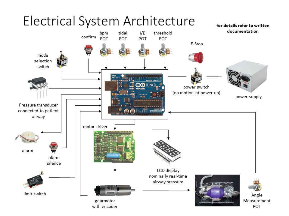
- Many parallel international efforts are underway to create open-source ventilators to provide emergency medical support to COVID-19 patients—and many of the projects use the Arduino! E.g. see this electrical system architecture diagram from the Emergency Ventilator team at MIT. While we are not in making life-supporting devices in this class, it’s nonetheless heartening to see that some of our skills might actually be able to be helpful in times of real crisis.
- Review of expectations for in-person prototyping with reference to the relevant project assignment page section
- Preview of class plan for Monday’s prototype presentations as explicated in the relevant project assignment page section
- Remainder of session is spent checking in on groups.
Monday, April 6th: Prototype critique
- Critique runs as per this schedule
Wednesday, April 8th: Prototype debrief and forward planning
- Class discussion about how the prototype critique went (overall: successfully, it seems!)
- Quick demo of a trick that seems will sometimes help Tinkercad’s simulation run more effectively: add a
delay(10)or so in yourloop. This is sort of counterintuitive! But it does at least sometimes make a difference. - Team meetings for the remainder of class.
Monday, April 13th: Guest speaker Laura Poskin
- Laura Poskin, MPSG is a gerontologist who heads Age-Friendly Greater Pittsburgh, a local organization that works to make Southwestern Pennsylvania a friendly, livable place for people of all ages.
- She joined us for about an hour to talk about her work and answer student questions. (Her slides are available for download at the course Canvas site.)
- If you’re interested in learning a bit more about her, her work, and her organization, I recommend her TED talk that she just gave in November.
- The rest of the session was in team meetings, with Zach and Harshine briefly meeting with everyone to briefly address their final-stretch Gantt planning documents and make sure everyone was on track and clear about roles and responsibilities moving forward.
Wednesday, April 15th: Logic lesson and work time
- Announcements
- There’s ongoing research into the ways students use the Physical Computing Lab’s inventory and we solicit some volunteers who are willing to have a 10-minute chat about it with an undergraduate researcher
- You can expect an email soon from Kelly Delaney at IDeATe letting you know about an end-of-semester virtual share-out of some sort (filling in the space that normally Meeting of the Minds would be). I encourage you to share some work!
- Tomorrow (Thursday morning) 10:00–10:40 a.m. Pittsburgh time there will be a “Coffee Connect” event online, which is meant to help foster simple intergenerational connections between strangers. (Typically the event is held at a physical cafe in Pittsburgh.) Go to Virtual Senior Academy and make an account there to sign up. The event should be a nice opportunity to say hi to some new people and help all of us reduce our isolation a bit. Hope to see you there!
- Speaking of…there’s a very fun app called Quarantine Chat which pairs you with a random stranger for a phone chat at some time during the day. I have had some lovely conversations with all sorts of people. I recommend giving it a shot.
- I will be co-teaching a course in the fall, 62-362 Electronic Logics && Creative Practice. Heidi Wiren Bartlett, an artist and designer, is the other instructor in the course. 62-362 a creative extension of some of the technologies we’ve addressed together in this class, engaging with deeper explorations of some electronics and computing ideas to build rich artful interactions. Happy to answer questions—please let me know if you’ve got them.
- Interesting-things-to-know-a-bit-about: digital logic (building out hardware logic with 74xx series chips)
- Using a 7408 to build a simple AND circuit (driven by two pushbuttons)
- Adding a 7432 to build (A AND B) OR C (this time with three pushbuttons)
- Contrasting these with the equivalent built with “firmware” on an Arduino
- See (and copy from) our in-class example in Tinkercad if you like
- Remainder of class time is given for groups to work as they see fit
Monday, April 20th: Alternative devices and work time
- Voting on final documentation due date: it will be Friday, May 8th, at 5 p.m.
- Note: final due date for all oustanding work is Monday, May 11th, at 5 p.m.
- Harshine presents on different devices useful for IoT projects: NodeMCU, Raspberry Pi, and Particle Argon
- Final presentations/critiques will be on Monday 4/27 as well as Wednesday 4/29; see the course Canvas site for details of when which team is presenting.
- Rest of class is an open work session.
Wednesday, April 22nd: work day
- I’m getting 410 errors from Tinkercad from Homework 5…sigh. To work around that, please make your assignment publicly viewable, get the share link, and add it as a comment to the homework submission in Canvas. Once I’ve gotten the chance to check it, I’ll let you know and you can make it private again.
- The IDeATe class “Game Design, Prototyping, and Production” (53-471) is hosting a virtual playtesting, available here. There are some fun games! I recommend checking it out.
- We discuss a few minor housekeeping notes for Monday’s and Wednesday’s presentations (how to screenshare a slide deck, what kind of material to include in your presentation, etc.)
- Upcoming office hours slots:
- Zach immediately after class today
- Harshine on Friday 4/26 4–6 p.m.
- Zach on Sunday 4/26 6–8 p.m. (as voted on during class)
- or email Zach with a question or request to meet. Happy to help!!
- Remainder of class is work/check-in time.
Monday, April 27th: First round of final critiques
- Presenting today:
- Team Cynthia
- Team Emily
- Team Diane
- Team Lynne
- See Canvas for links to the Zoom recording as well as individual team slide decks.
Wednesday, April 29th: Second round of final critiques
- Presenting today:
- Team Yale
- Team Frederick
- Team Beth
- Team Jane
- See Canvas for links to the Zoom recording as well as individual team slide decks.
- Farewell! Wishing all of you a healthy finish to the school year, a good summer, and looking forward to seeing your faces back on campus in the fall.
