CRT Nostalgia
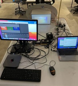
Left mac mini with monitor display indicates the Millumin file pushing content to the projectors; right laptop uploads Arduino
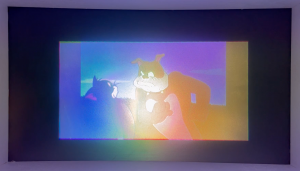
Full color image
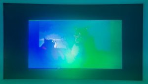
Cyan image
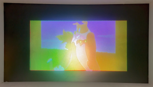
Yellow image
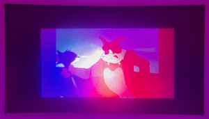
Magenta image
For this project, I wanted to explore the magic analog logic of additive light mixing in a playful, nostalgic interactive experience. The eventual coordination of my three projectors simulates the effect of a single old CRT projector, and the content was similarly inspired by early childhood memories of being transfixed by cartoons playing on my grandmother’s clunky CRT TV. The experience is made more intimate and immersive because the viewport is designed for one user to interact at a time.
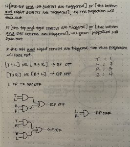
This simple box has a viewport on one side and a projection screen on the opposite face, and is fitted with an oblong board embedded with 4 IR proximity sensors. 3 projectors divide a video of early 2000s cartoons into their red, green, and blue channels (processed through Millumin), which combine to create a full-color image when overlaid perfectly on the screen; old CRT projectors originally had 3 lenses for each primary color, as opposed to modern digital projectors which emit the combined light through a single lens. Each projector has a light valve secured in front of the lens that becomes opaque when triggered by certain combinations of readings from the proximity sensors. When a translucent light valve receives a high electrical signal, it becomes opaque; the corresponding projector’s channel of light is removed from the combined image, resulting in the secondary colors of light: cyan, magenta, and yellow.
I had two forms of logic in this piece: the first being the science itself of mixing the primary colors of light, the second being the combinations of sensors designed to trigger the light valves.
red AND green AND blue–> white (full color)
red AND green –> yellow
red AND blue –> magenta
blue AND green –> cyan
Progress Images:
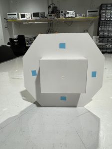
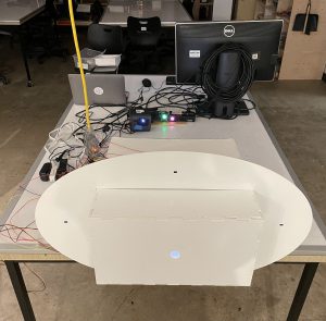
front of viewing box; 4 blue rectangles indicate sensor placement
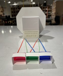
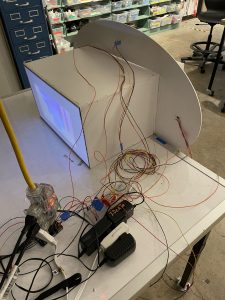
rear of viewing box; red, green, and blue channel projectors will map onto a single surface
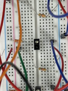
Wiring with the sensors in-board
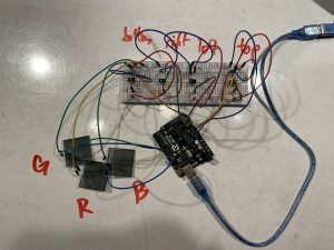
4 sensors successfully spoke to 3 projectors through logic coded in Arduino
Process reflection:
Given that I had no prior experience with electrical hardware, I definitely struggled with initial ideation; I wasn’t sure what functional and conceptual possibilities there were given my limited knowledge, which is why I latched onto an example of simple pre-existing logic in the form of additive light mixing. If I had a stronger conceptual backing, I think I would’ve had more fun with the user experience of the piece. I ended up playing with a lot of unusual tools, namely the light valves, IR proximity sensors, and mini projectors, and I also interacted with Arduino and laser cutting for the first time on this project. Towards the end of the process, I drained a lot of time soldering and re-soldering the sensor wires in different configurations; we tried to solder the two grounds and a resistor together coming directly off of the sensor, which ended up preventing signal from reaching the breadboard. Ultimately, running into these issues actually gave me a better understanding of the electronics I was working with, and despite the setbacks, the scope of my project was surprisingly feasible.
If I had more time, I definitely would have added height to the box so the user could interact with it while seated in a chair. I also would have added more cartoon content, and if I had more time to dedicate to Arduino/software skills, it would’ve been fun if the user could “change the channel” while looking through the viewport. I also could have fine-tuned the projector positions; in the full color image you can see that there are some hotspots where a projector is off-center from the image and the distribution of color is a little uneven.
Final Arduino code, guided by Prof. Zacharias:
const int TOPSENSOR = A0; // shortcut to refer to the top sensor pin later
const int LEFTSENSOR = A1; // shortcut to refer to the left sensor pin later
const int RIGHTSENSOR = A2; // shortcut to refer to the right sensor pin later
const int BOTTOMSENSOR = A3; // shortcut to refer to the bottom sensor pin later

const int REDVALVE = 9;
const int GREENVALVE = 10;
const int BLUEVALVE = 11;

const int PROXTHRESHOLD = 40; // values above 40 are "high"
bool TopClose, LeftClose, RightClose, BottomClose;

void setup() {
  pinMode(TOPSENSOR, INPUT); // we will be reading the top sensor pin as an input
  pinMode(LEFTSENSOR, INPUT); // we will be reading the left sensor pin as an input
  pinMode(RIGHTSENSOR, INPUT); // we will be reading the right sensor pin as an input
  pinMode(BOTTOMSENSOR, INPUT); // we will be reading the bottom sensor pin as an input

  pinMode(REDVALVE, OUTPUT);
  pinMode(GREENVALVE, OUTPUT);
  pinMode(BLUEVALVE, OUTPUT);

  Serial.begin(9600); // starts serial communication at 9,600 baud (the rate)
}

void loop() {
  int readVal1; // initialize a new integer to store the photocell value
  readVal1 = analogRead(TOPSENSOR); // do the analog read and store the value

  int readVal2; // initialize a new integer to store the photocell value
  readVal2 = analogRead(LEFTSENSOR); // do the analog read and store the value

  int readVal3; // initialize a new integer to store the photocell value
  readVal3 = analogRead(RIGHTSENSOR); // do the analog read and store the value

  int readVal4; // initialize a new integer to store the photocell value
  readVal4 = analogRead(BOTTOMSENSOR); // do the analog read and store the value

  if (readVal1 > PROXTHRESHOLD) TopClose = true;
  else TopClose = false;
  if (readVal2 > PROXTHRESHOLD) LeftClose = true;
  else LeftClose = false;
  if (readVal3 > PROXTHRESHOLD) RightClose = true;
  else RightClose = false;
  if (readVal4 > PROXTHRESHOLD) BottomClose = true;
  else BottomClose = false;

  if ((TopClose && LeftClose) || (BottomClose && RightClose)) {
    // RedValve becomes opaque
    digitalWrite(REDVALVE, HIGH);
  } else digitalWrite(REDVALVE, LOW); // if REDVALVE is not high (opaque), return to transparent

  if ((TopClose && RightClose) || (BottomClose && LeftClose)) {
    // GreenValve becomes opaque
    digitalWrite(GREENVALVE, HIGH);
  } else digitalWrite(GREENVALVE, LOW); // if GREENVALVE is not high (opaque), return to transparent

  if (LeftClose && RightClose) {
    // BlueValve becomes opaque
    digitalWrite(BLUEVALVE, HIGH);
  } else digitalWrite(BLUEVALVE, LOW); // if BLUEVALVE is not high (opaque), return to transparent


  delay(50); // slow the loop down a bit before it repeats
}