by Lissa Biltz, Victoria Yong, and Robert Zacharias
Due: 5/11/2017
Abstract
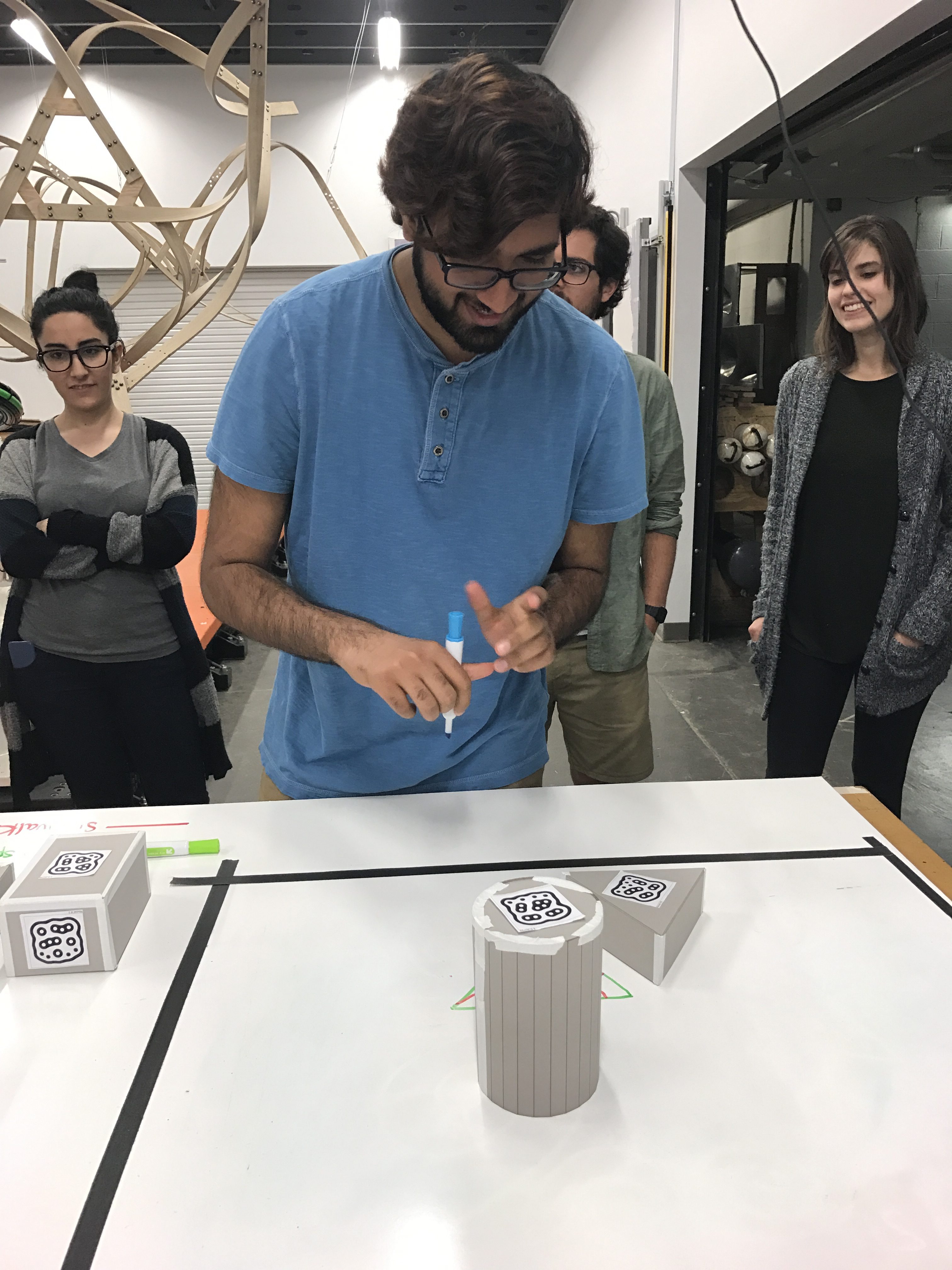
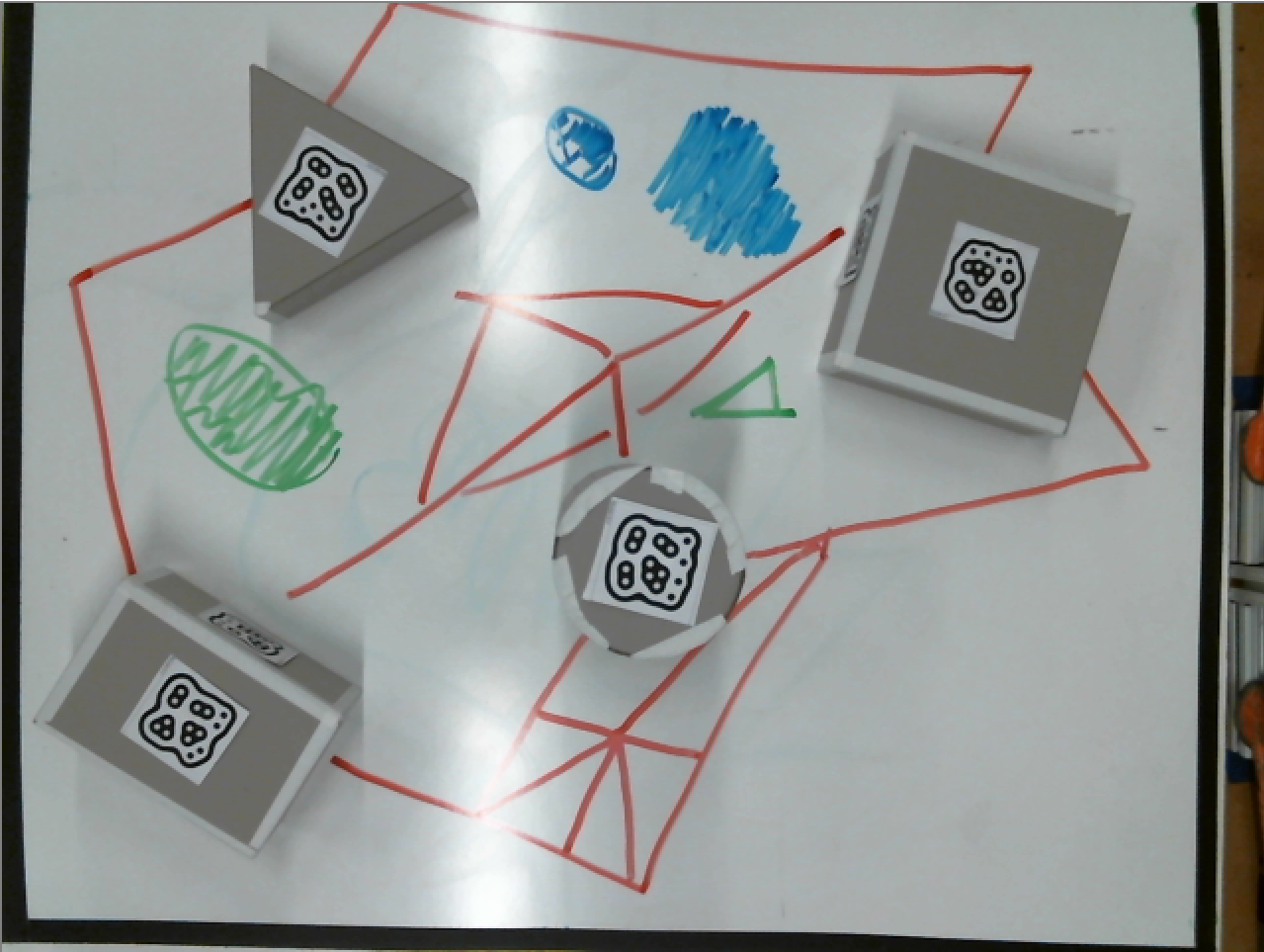
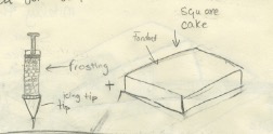
This project aimed to provide a playful method of designing a city block on a piece of cake using playful user input and a frosting-based output generated by an ABB robot and a Grasshopper script. On a plain white surface, a user arranges a set of cardboard building models, and using dry-erase markers draws walking paths, green spaces, and water bodies around the buildings. An image of the scene is captured from above and software identifies the position and orientation of the buildings and marker drawings. An ABB robot with a custom end-of-arm effector extrudes cake frosting in the form of the buildings and other drawn features. The model is scaled down by a factor of four and extruded onto the top of a flat cake, thereby making a cake city block.
Objectives
- Use fiducial-reading system to identify the orientation and position of known shapes and import their geometry into Rhino
- Use computer vision to capture colored paths drawn on whiteboard
- Pipe a city block consisting of legible frosted shapes generated from the above data onto a cake, using a custom end effector on an ABB industrial robot
Implementation
Motion and Depth Capture
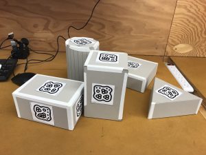
We laser cut models that represented buildings and attached uniquely numbered fiducial markers to each one. By attaching different markers to different faces, the boxes could be reoriented about their own axes to simulate differently proportioned buildings: whichever marker faced up was the one that was used for building identification.
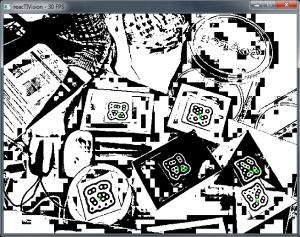
Building forms were scaled to have similar dimensions so as to increase likelihood of successful modeling of a city block. Choosing to build model buildings using regular volumes like a cylinder, rectangular prism, and triangular prism meant that the models were simple to design and construct. We used the reacTIVision system, version 1.5.1 (http://reactivision.sourceforge.net/), to generate and track fiducials, each of which was associated with predefined planes in Rhino.
Color and Vision Capture
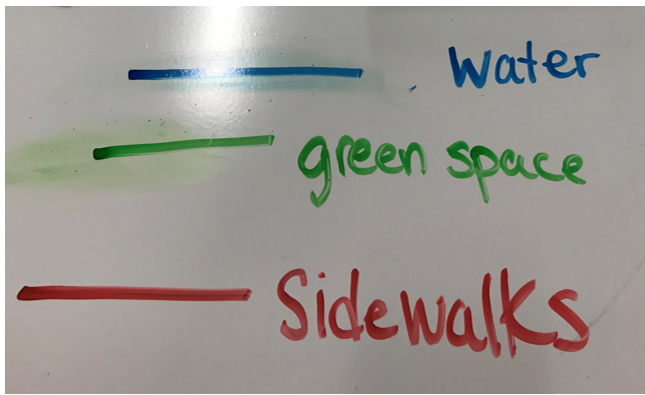
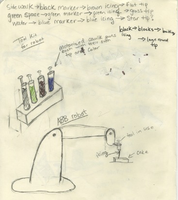
Sidewalks, water elements, and green spaces are represented by three different color whiteboard markers (red, blue and green respectively) These colors were chosen because they were intuitive, but also different enough to work effectively in computer vision.

A webcam views the colored paths from above as they are drawn, and a python2 program using OpenCV3 installed via Anaconda (https://anaconda.org/menpo/opencv3). First the initial image is split into three images, each with only one color. Each image is then converted to grayscale, and the openCV drawContours function detects each path and saves a .data file of all points of each color.
Grasshopper then takes these data files and converts them into a tree, so each path is easily converted to robot code.
Frosting Extrusion System
Physical considerations and fabrication
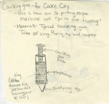
We went through an iterative design process to create an end-of-arm effector for the ABB robot capable of extruding frosting using a commercially available frosting press (Wilton 415-0906 Dessert Decorator Plus).

In order not to compromise food safety, we did not want to modify the frosting press in any way, for instance by replacing the pushing rod with our own rack and pinion. We chose a linear actuator to apply pressure to the frosting push rod; after comparing different models available, we settled on an 8″ travel linear actuator from Firgelli Automations, drawing up to 5A at 12V, capable of delivering 35 lbs. of force (part number FA-PO-35-12-8). Frosting, especially if it’s chilled and is being forced through a small cupcake frosting orifice, is actually quite resistive to flow and so at times the linear actuator may have been running at or near its rating.
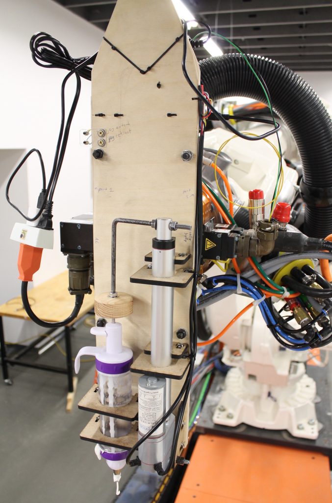
We developed digital models of the physical configuration of our end-of-arm assembly; we hand-drilled the base plate with holes corresponding to the mount points for the linear extruder and frosting press, and mounted custom lasercut parts to secure both of these parts. Mechanical plans, including Solidworks part files and DXF lasercut plans, are available in the project Github repository: https://github.com/robzach/cakeCity.
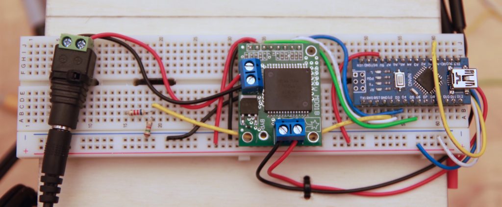
Electronics
Our end effector needed to receive properly synchronized control signals from the same source that was running the main motion process on the robot, so it was vital that the signals come through an onboard facility of the robot. Thankfully, our ABB IRB-6640 is configured with digital outputs that can deliver signals to the end effector. Using a simple voltage divider, the ABB’s 24V signal was brought down to a 5V signal appropriate to the logic level of an Arduino Nano. The control scheme was extremely simple: if the Arduino received a 10 millisecond high pulse, it would stop the extruder motor; if it received a 20 millisecond high pulse, it would continuously advance it at a given rate which we had previously determined empirically (and which was hardcoded into the firmware). We used a high-current H-bridge motor driver to deliver power to the motor (Pololu part 705, a carrier board for the VNH3SP30).
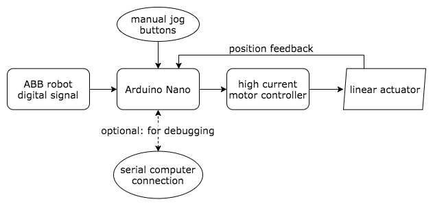
The motor advance was rate-controlled using position feedback from the linear actuator’s built-in multiturn pot; this proved to be important because of the nonlinear, resistive nature of the frosting load. For convenience, our end-of-arm tool also included momentary pushbuttons to jog the actuator in either direction. (The jog buttons were especially useful for deinstalling and installing the frosting extruder, which needed occasional refilling during robot operations.)
Firmware note
A single misread “start” or “stop” command could significantly disrupt the robot output, because until it receives a different command, the effector script is designed to continue in its current state indefinitely. For this reason, and because the Arduino often had a somewhat “busy” control loop that it would be running to keep the motor in the properly commanded position, we used an interrupt-driven scheme to read the widths of incoming pulses as reliably as possible. Here is the general logic of the ISR (interrupt service routine) that was called on every change in the pulseIn pin:
void readPulse(){
  static unsigned long startTime = 0;
  static uint8_t lastState = 0; // state of the pin last time the interrupt was triggered

  uint8_t readState = (PIND & (0b00000100)); // port access is quicker than digitalRead

  if (readState != lastState) {
    if (readState) startTime = micros(); // if just went high, start timer
    else {
      diff = micros() - startTime; // if just went low, stop timer and count difference
      // use "diff" to drive motor outside of ISR
    }
    lastState = readState;
  }
}
Note that the global variable diff should be declared as a volatile since its value will be affected by the ISR. The interrupt-driven model is a superior scheme to using the Arduino’s built-in pulseIn() function, because that function is blocking: if left in its default configuration it can hang for up to 1 second while waiting for the second half of an already-begun pulse to complete. Firmware is available on the project Github page, as linked above.
ABB Rapid Code Generation
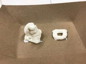
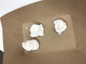
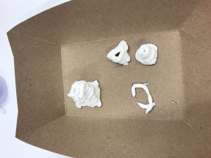
Once the building and colored drawing path data was acquired, it was scaled down by a factor of four to fit on the cake. The reacTIVision and OpenCV data were interpreted separately and were in two different files before they were sent to the robot. While it was clear that the color capture data was meant to be translated into two-dimensional polylines with subdivisions, generating the buildings would be a challenge as they were meant to be a series of offset rings of frosting to be stacked in three-dimensional figures. Before deciding how to script the offset lines, we manually frosted buildings to see which pattern would be the most legible. We settled for separating the polygonal geometric figures into line segments with their own entry and retract points instead of compiling them into a typical cupcake swirl since we assumed that frosting could not turn a sharp corner.
A series of pathways was then generated in Grasshopper to emulate the most effective pattern that we had piped by hand. These pathways were initially polylines, which were then separated into line segments or individual curves. The overall forms are slightly tapered to allow the frosting rings to sit on each other without falling over.

These paths were then divided, generating planes at their endpoints and in the cylinder’s case, midpoints.
After carefully separating each geometric input into classes (boxes, prisms, cylinders, polylines), we input the planes into a HAL code template that would create a series of movements and frosting extrusion commands to be written into Rapid code. Each plane became a command for the robot to move to a certain position on the table. Then, commands for starting (ToolOn) and stopping (ToolOff) the flow of frosting were methodically woven into the series of planes so that the machine would extrude frosting at the right moments to generate lines on the cake. In order to organize the paths, the code was partitioned so that every item in a particular group would be extruded before moving onto the next group. The paths were frosted in this order: box, prism, cylinder, then polyline.
Outcomes
We succeeded in creating a frosting apparatus that could extrude frosting on command. We also successfully captured image data from reacTIVision and OpenCV to be converted to ABB Rapid instructions, resulting in code that placed frosting on a cake in a pattern that we correctly generated. What had been gathered of the color data was smoothly represented by the frosting patterns.
However, we were not able to create scaled building figures from frosting. There had been so many planes (at least 2,000 per building!) generated from the desired offset pattern that the Grasshopper script crashed each time we attempted to convert the data to HAL code. We had to settle for extruding a single frosting ring for each figure, so we had building footprints instead of full buildings. Additionally, the color capture data for our demo was incomplete because shadows had been cast over the lines. While the machine extruded frosting in the patterns that we intended, excess frosting was pushed out even when ToolOff commands had been sent to the robot. The shapes were illegible because of this.
Contributions
Lissa worked on OpenCV/Python color capture, created the SolidWorks model of the plate to be attached to the robot, and compiled and edited the video.
Victoria worked on ReacTIVision/Grasshopper geometry capture, created the building model inputs, and compiled the two image capture Grasshopper scripts into a single file to generate the ABB Rapid code.
Zach (“Robert”) focused on frosting extruder design, fabrication, electronic implementation, and firmware development.
Related Works
Dinara Kasko’s architectural pastries: http://www.dinarakasko.com/
Unibot Cake Decorator: https://www.youtube.com/watch?v=xdLIRwdCSyM
]]>
RoboZen
Cecilia Ferrando, Cy Kim, Atefeh Mhd, Nitesh Sridhar
5/10/2017
Abstract:
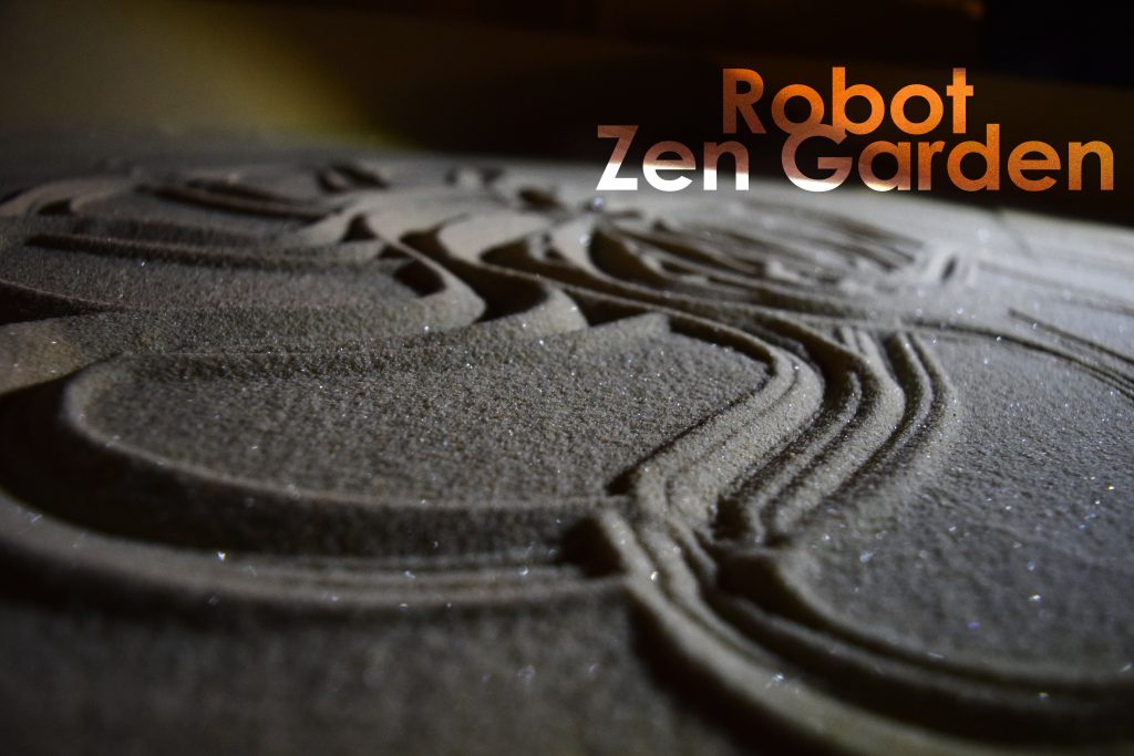
Our human-machine workflow involve using a sandbox as a zen drawing template. By using sand as the drawing medium, it is easy to create and reset patterns. Modeling sand is on one side a predictable action, on the other it also entails an unpredictable component due to the complex behavior of granular materials.
The workflow was initially designed as follows:
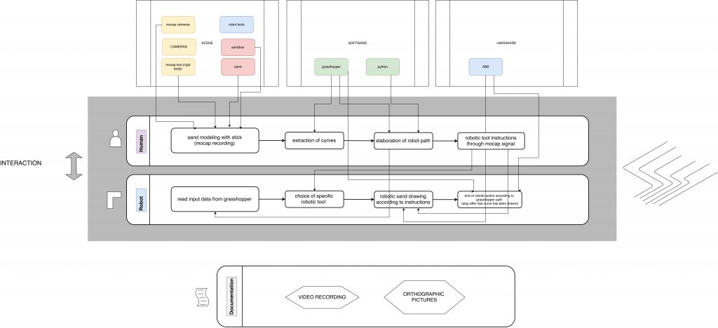
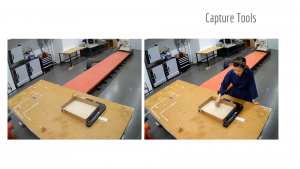
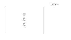
As a pattern or shape is being drawn, Motive captures the motion of the hand tool moving through the sand. Grasshopper takes in a raw CSV file as an input and it preprocesses it in the following way:
- points are oriented in the correct way with respect to the Rhino model
- the points that are not part of the drawn pattern (for example the ones recorded when the hand was moving in or out the area) are dropped
- curves are interpolated and smoothed out
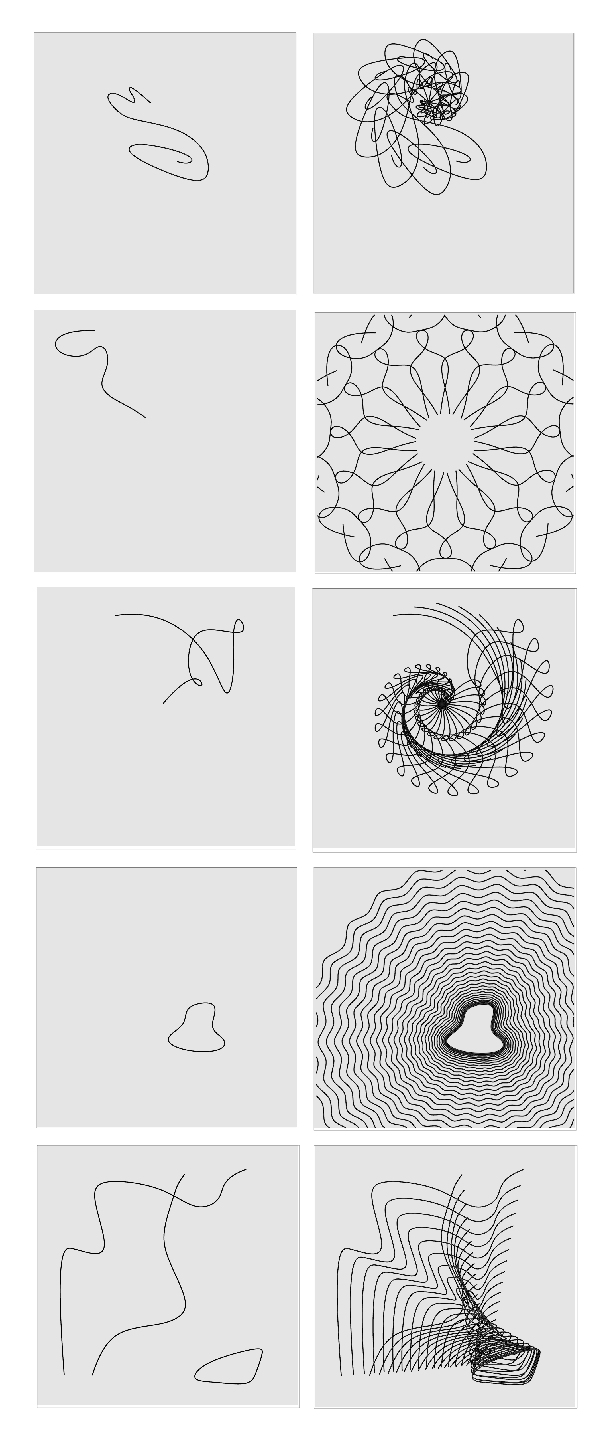
The preprocessed input curve (or curves, in the case of a multiple curve), is passed to a GhPython component that dispatches the input according to determined parameters that are intrinsic to the input. In particular, the code checks whether the input curves are:
- closed, open or self-intersecting
- long or short with respect to the dimensions of the box
- positioned with large or small relative angle with respect to the center or the box
- complex or simple
Depending on the nature of the input, the curves are dispatched to the final implementations in the following way:
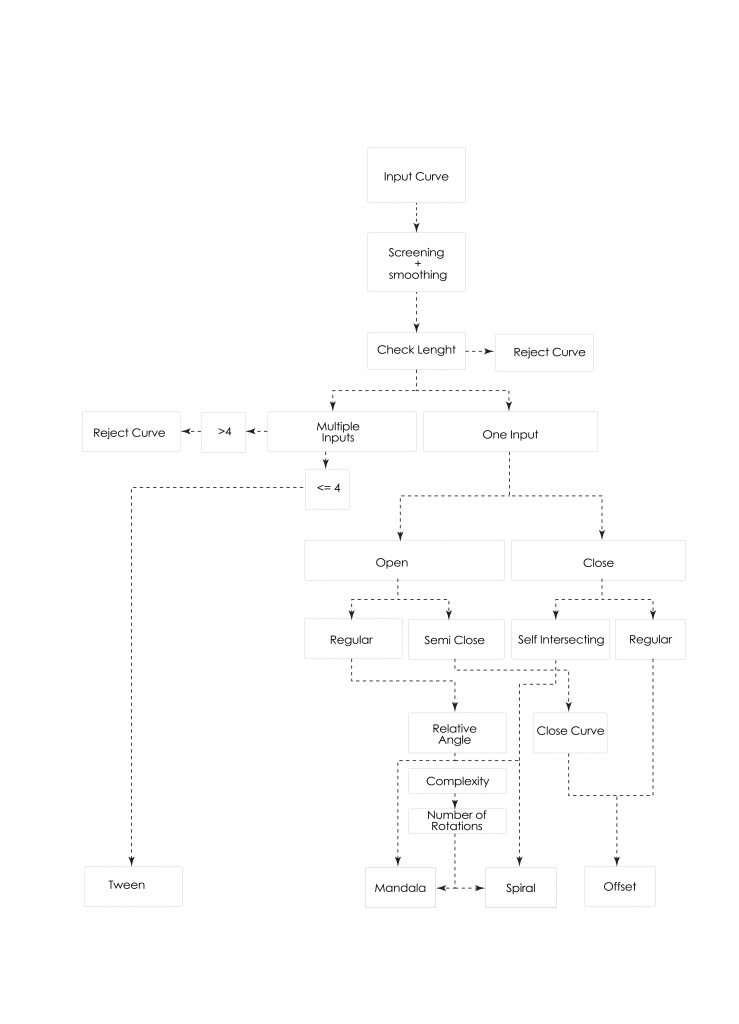
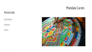
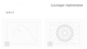
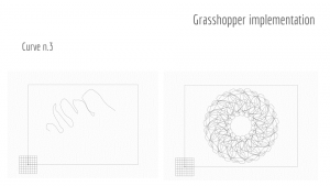
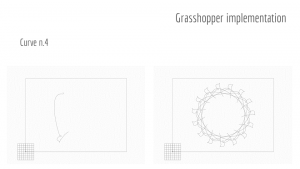
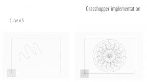
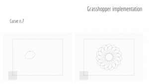
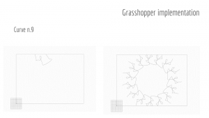
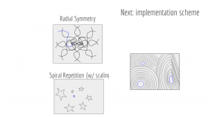
Within the mandala/radial symmetry mode, the software reflects and rotates the source curve into the form of a mandala with rotational symmetry that has as a center the center of the box. Differently, the spiral mode rotates the figure with respect to the endpoints of the curve, with a variable scaling factor that decreases the size of the input curve as it is patterned outwards.
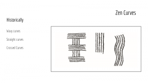
The user might choose to draw multiple figures on the canvas. A maximum of four figures is allowed by the system. In this case, a tweening mode interpolates between multiple curves by computing a number of intermediate instances between consecutive curves. These patterning modes will also treat closed curves as objects, aiming to avoid them rather than intersecting with them or trying to cover them. In this way the patterning is reminiscent of the rake lines that are seen in zen gardens which avoid the rocks and small areas of greenery that are located within the garden.
When the offset mode is activated by a closed curve, the implementation follows the same structure as the offset command in Grasshopper, except that a zig-zag transformation is applied as the figure is offsetted outwards. Also, the offset distance is variable.
Objectives:
The purpose of the Zen Robot Garden is to create an experience where the user can view the robot drawing patterns in the sand both as a meditative experience (such as creating a mandala or a zen garden pattern) and as an educational experience to learn how symmetries, scaling and other geometric operations can entail very different results based on a set of different input parameters. There is a component of surprise in seeing what the final sand pattern looks like, and this is due to two elements:
- the hard-to-predict aspect of the completed pattern
- the self-erasing and complex behavior of the sand as it is being modeled
As the users continues to explore the constraint space of the sandbox curves, they can implicitly infer the parametric rules and therefore learn how to bring out different patterns.
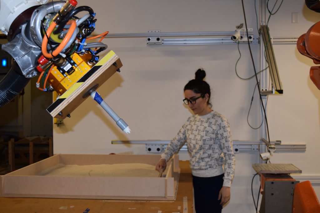
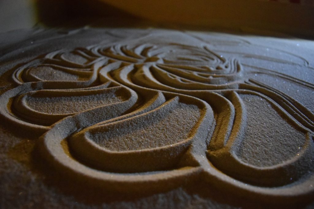
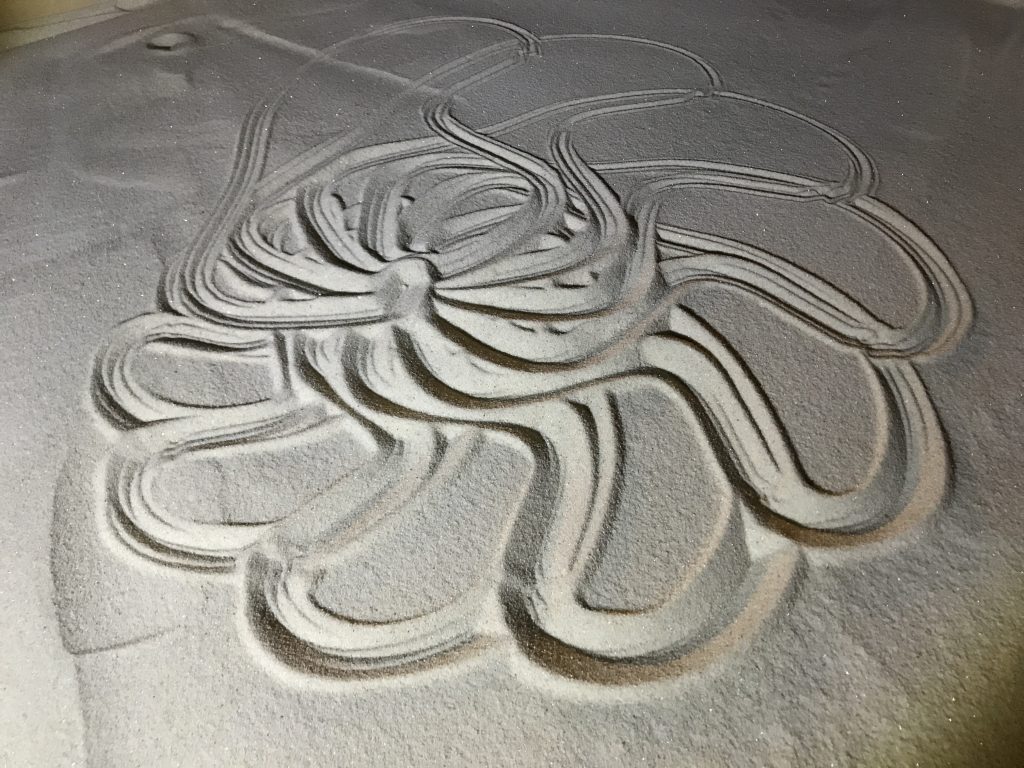
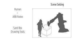
The ABB 6-axis robot uses a tool with a fork-like head to act within the same sandbox as the user, in order to create small, rake-like patterns in the sand similar to those that can be seen in a true zen garden. The collaboration between the robot and human user allows the user to create complex forms out of simple shapes and drawing movements. Watching the robot perform the task puts the user in a relaxing state similar to the meditative function of a zen garden.
Implementation:
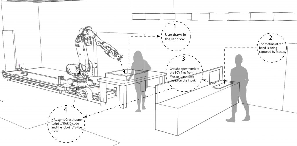
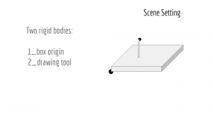
We chose to use a sandbox because sand is easy to work with and draw in but also simple to reset. Additionally it creates a collaborative workspace for the robot and human user, allowing them to explore the medium together. Watching the robot slowly transition through the sand, displacing old curves in place of new ones, creates a relaxing atmosphere and echoes the impermanence and patience shown in true zen garden pattern making.
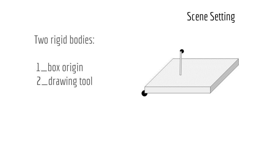
We started by having a rigid body for the sandbox as well as the drawing tool to help capture the plane of the box. We also captured it as a work object for easy use with the robot. The drawing tool was used in repeated takes to capture the movement of the user’s hand as a curve that mirrored what they had drawn in the sand.
Outcomes:
We were able to create a logical system that allows the user to discover different outputs based on their input drawings without having to open up settings or menus. The transformations and output parameters used to create the final curve patterns are directly based off of properties of the input curves, which creates a process that seems opaque and surprising at first, but can be uncovered through repeated use.
The most difficulty we had was in terms of taking a curve output from Motive’s motion capture and bringing it into Grasshopper, as some of the capture settings can vary between takes and it was difficult to create a parametric solution that covered all the curves while still leaving them unchanged enough to be analyzed and reinterpreted for the robot output.
Contribution:
All the group members collaborated in shaping and fine-tuning the initial concept for the workflow.
Cecilia and Atefeh designed the Grasshopper script which takes the motion capture data and extracts the user’s input curves. They also coded the script that generates the curve output based on the parametric properties of the input.
Cy created the HAL script which takes the output curves and generates the robot’s motion paths from the curves. She also CNC routed and assembled the sandbox.
Nitesh designed and 3D printed the tooltip for the robot, and helped set up the work objects and robot paths, and supplied sand.
Inspiration:
Procedural Landscapes – Gramazio + Kohler
Photo Documentation:
]]>
Project Team: Dyani Robarge & Jack Fogel
Human Machine Virtuosity, Spring 2017
ABSTRACT
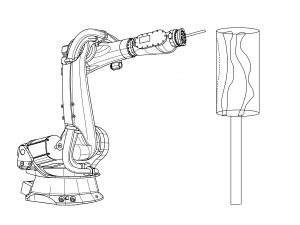
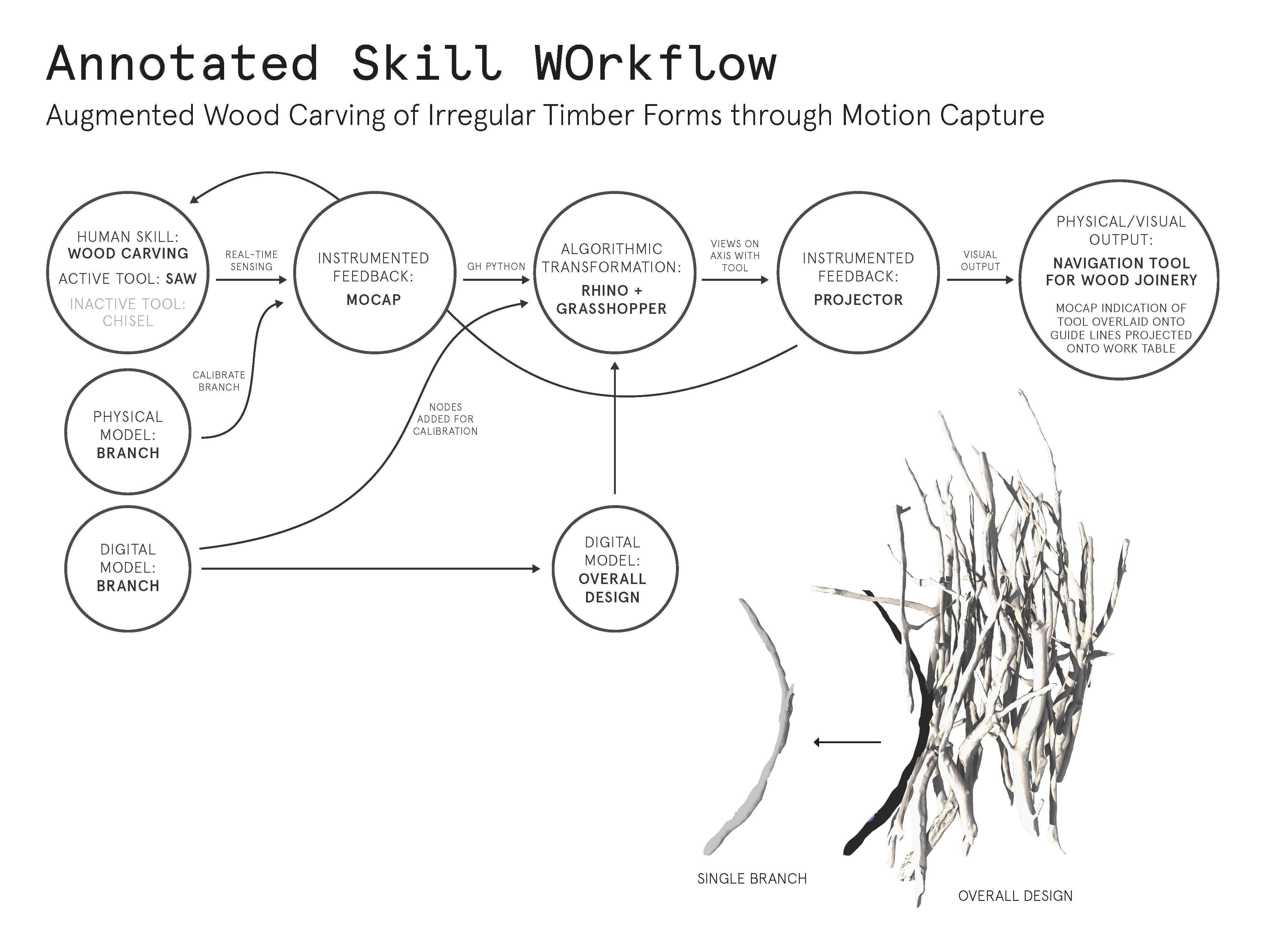
The Augmented Carve seeks to develop a woodworking tool guidance system for aiding in the construction of 3D aggregated irregular geometries, in this case branches. The motion capture system tracks the location and orientation of both tool, a ryoba pull saw, as well as individual wood parts. A projection directs the user where to make half lap cut to join two beaches together, ultimately creating the structure designed on the computer through a series of members.
OBJECTIVES
Rather than working with dimensional lumber, the half lap joinery connects a dense collection of large, irregular tree branches. Working with a catalog of highly-unique parts adds an extra challenge in building this augmented construction system. Our objective is to use this augmented system to make accurate, complex carves which vary in size, location and orientation. Our hope is that the precision of these complex intersections can be translated smoothly from digital model to physical work space.
IMPLEMENTATION
To start, individual branches are made into high-resolution digital models through the use of open source photogrammetry software. Once the mesh models are properly scaled and cataloged, 3-4 nodes are placed on each digital branch model. Holes are drilled into the physical branches concurrently to ensure an accurate representation of the motion capture nodes in digital space. Once the nodes are fixed in place, the branch and ryoba saw can be linked and tracked as ‘rigid bodies’ within the motion capture software. Using a projector, tracking data is displayed on the work table next to the user.
The worker then affixes the branch securely to the table, making sure to keep the carve areas visible and accessible. Our team initially designed a fixture to affix each branch to the work table, but after several carve tests with branches of various sizes we quickly found the fixture to be an unnecessary element in the process. Once the worker has their branch securely fastened, the saw can be aligned to each cut area.
As the user moves their tool and a branch into the work cell, a dynamic user interface occurs. The camera zooms in onto individual carve regions and out to view the entire work space depending on the proximity of the tool to each carve region. Carve regions are marked by two outer alignment curves. The lines help the worker guide their tool in space. Circles above the saw endpoints act as a virtual level by giving clear indication of correct approach angles for each unique carve. Relaying real-time feedback of the tool’s movements through space allows the motion capture system to guide the user as they work.
OUTCOMES
We feel that this woodworking guidance tool provides intuitive feedback to the user and yields relatively accurate results, however there is room for much improvement. The low resolution of the projector greatly affected the tolerance of cut location, however we aimed to make most of the cuts smaller so with a small adjustment they would fix snug. The interface is very clear to us to use as we designed it, however its unclear if others would have the same ease of use as we did not test it with others. Overall, there are several features we noted throughout the process of creating this system which could be improved and expanded upon, but as the project stands it accomplishes much of what we had hoped.
CONTRIBUTION
Early in the project, Jack built a working prototype of the table clamp fixture. Dyani generated the overall assembly of branches and outlined carve regions for each. The two shared equal responsibility in the development of the overall workflow, its layout as a projected user interface, as well as prototyping different versions of the system’s Grasshopper script.
-
Project Title
- Author 1, Author 2
- Submission Date
- URL of project video (typically up to two minutes)
-
Abstract
Provide a brief paragraph summarizing the overall goals and results.
-
Objectives
State your goals, and discuss what specific features are within scope for the project.
-
Implementation
Discuss your design choices.
-
Outcomes
Discuss the successes and failures of your choices.
-
Contribution
Please provide a clear statement of each author’s individual contribution to the outcomes.
-
Video.
Please embed a video which captures the intent and success of your project. As a general rule, these might be edited one to two minutes long. Please observe good camera and editing technique.
-
Photo Documentation
Provide captioned photos which support your discussion. Please consider the purpose of each photo and write a caption which helps the reader understand your intent. -
Citations
Please provide references or links to related work.

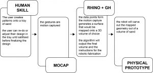
Written Description:
The initial steps in this workflow involve using a sandbox as a zen drawing template. By using sand as the drawing medium, it makes it easy to create and reset patterns. As a pattern or shape is being drawn, Motive captures the motion of the hand tool moving through the sand. Grasshopper isolates the curve and then based on an analysis of that curve, picks a mode for the output and generates it.
Within the mandala/radial symmetry mode, grasshopper reflects and rotates the source curve into the form of a mandala with rotational symmetry. Additionally there will be a mode for a spiral repetition mode with scaling that increases outwards from the center, and a mode for sectioning and patterning areas between closed curves. These patterning modes will also treat closed curves as objects, aiming to avoid them rather than intersecting with them or trying to cover them. In this way the patterning is reminiscent of the rake patterns that are seen in zen gardens which avoid the rocks and small areas of greenery that are located within the garden.
The ABB 6-axis robot will use a tool with a fork-like head to act within the same sandbox as the user, in order to create small, rake-like patterns in the sand similar to those that can be seen in a true zen garden. The collaboration between the robot and human user will allow the user to create complex forms out of simple shapes and drawing movements, and then watching the robot perform the task in a relaxing state similar to the meditative function of a zen garden.
]]>
Input:
Transformation:
![]()
Output:
Written Description:
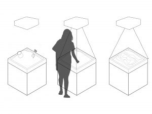
The first step in this workflow involves using a sandbox for the drawing template. By using sand as the drawing medium, it makes it easy to create and reset patterns. Once a pattern is drawn it can either be modified or saved to be used to design the final sculpture. The Kinect depth camera will analyze the drawing pattern as a curve and Grasshopper will use that to generate a sculptural volumetric form.
Grasshopper will calculate and display the form, updating it as you draw, clear, and redraw curves in the sand. This will be based off of revolving or sweeping through the curves to create a vase-like form. After adding enough curves and adjusting the spacing and look of the curves, you can finalize the form for fabrication.
The final form could be fabricated in a multitude of ways from the 3D model grasshopper generates. We have decided to use the ABB 6-axis robot to fabricate the finalized form out of sand.
]]>
project context | motivation | scope | implementation
The system our team is developing harnesses the learned skill of woodcarving and applies this trade to an augmented assembly process. Specifically, the project seeks to augment the process by which individual branches are carefully carved.
VIDEO: Wood Carving Half Lap Joint with Hand Tools
The first step in this process is the tagging and reality capture of the branches. This process yields a digital representation of each physical branch used in the overall design. The clear resolution of each branch’s unique features in their digital representations allows the designer to mark each physical and digital model with three nodes. Each branch is set as a rigid body within the system. In addition, the carving saw is also set as a rigid body. Once this set-up is complete, the worker is ready to begin carving.
As a branch moves into the work cell, its tag appears on table’s projected screen. The worker then affixes the branch to the table’s fixture system, making sure to keep the carve areas visible and without obstruction. Once this branch is securely fastened, the wood carver introduces the saw to the work area and prepares to make the first alignment cuts. Lines projected onto the work table beside the wood carver help he or she align the tool in space and give clear indication of the correct saw angle when approaching each carve.
The system acts as a guide by relaying real-time feedback of the tool’s movements through space. By giving agency to the artist, they are free to decide when the visual cues are useful and when their attention is needed elsewhere in the work cell. This method of augmented working leaves complete freedom of the wood carve itself to the artist. We prefer the flexibility of augmented craftsmanship over automation because it allows for creative decisions to be made throughout the production process.

Our team plans to begin creating this system by setting up the table fixture and testing various motion capture markers on the branches. While prototyping, we will continue working on the code which links the work cell, branches and tool to the digital model. This abstracted visual of the augmented process is crucial to the overall workflow. We plan to refine the projected visuals so that the wood carver is able to work seamlessly while interpreting information needed to complete the piece.
]]>

2.Annotated Drawings
Input:
Transformation:

Process:
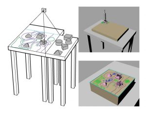
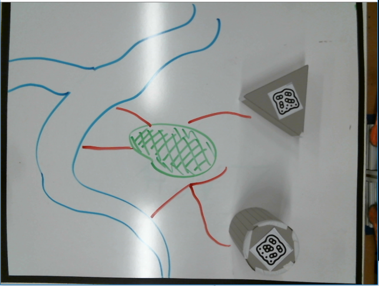
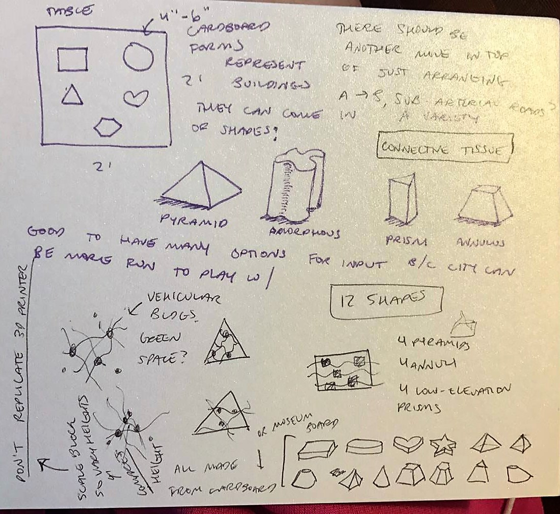
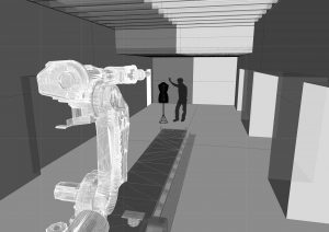
Left: Input, in which cardboard forms that represent buildings are arranged on a 2′ x 2′ table and whiteboard surface under a Kinect. Green spaces (green), roads (purple), and bodies of water (blue) are drawn in with markers. A boundary (cyan) for the cake is also drawn to indicate where to cut. The Kinect tracks the RGB values of the pathways and records the depth of each object in relation to the table.
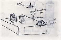
Upper right: Process, in which an ABB robot uses a caulk gun with different tips and colors of icing to pipe the different recorded features onto a large 18″ x 24″ sheet cake using the data it received from the Kinect. The data is now at 1/4 the size of the initial input setup as it is piped onto the cake. Icing materials are carefully chosen to ensure that the icing stands up when stacked and is solid enough to withstand minimal movement.
Lower right: Output, in which the finished cake is cut from the larger sheet. The process is repeated for different setups which turns out more cakes of different shapes and sizes.
3. Written Description
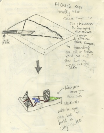
Remember playing with blocks as a child to make buildings and cities? Now imagine if those cities were actually made of cake. Our motivation with this project is to introduce children to urban planning concepts in a fun, interesting, and edible way, while valuing the deep artistry the goes into cake decorating.
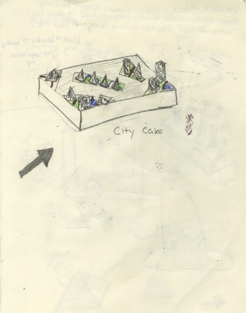
First a child defines the space by using specially shaped markers. A child arranges blocks to make buildings on a table as if they are city buildings, arranging them as if they were one block of a city. Sidewalks, green spaces, and water elements can be drawn in colored dry erase markers. A depth capture camera looking down from overhead captures the arrangement, shape, and color of the features. An ABB then pipes the features using conventional cake piping techniques onto a single cake, in the process reducing its dimension by a factor of ~4–6. Once there are enough blocks created in this way, they can themselves be arranged in the same space to form a cake city consisting of cake blocks.
]]>
Physical Workcell Diagram
]]>
Intro
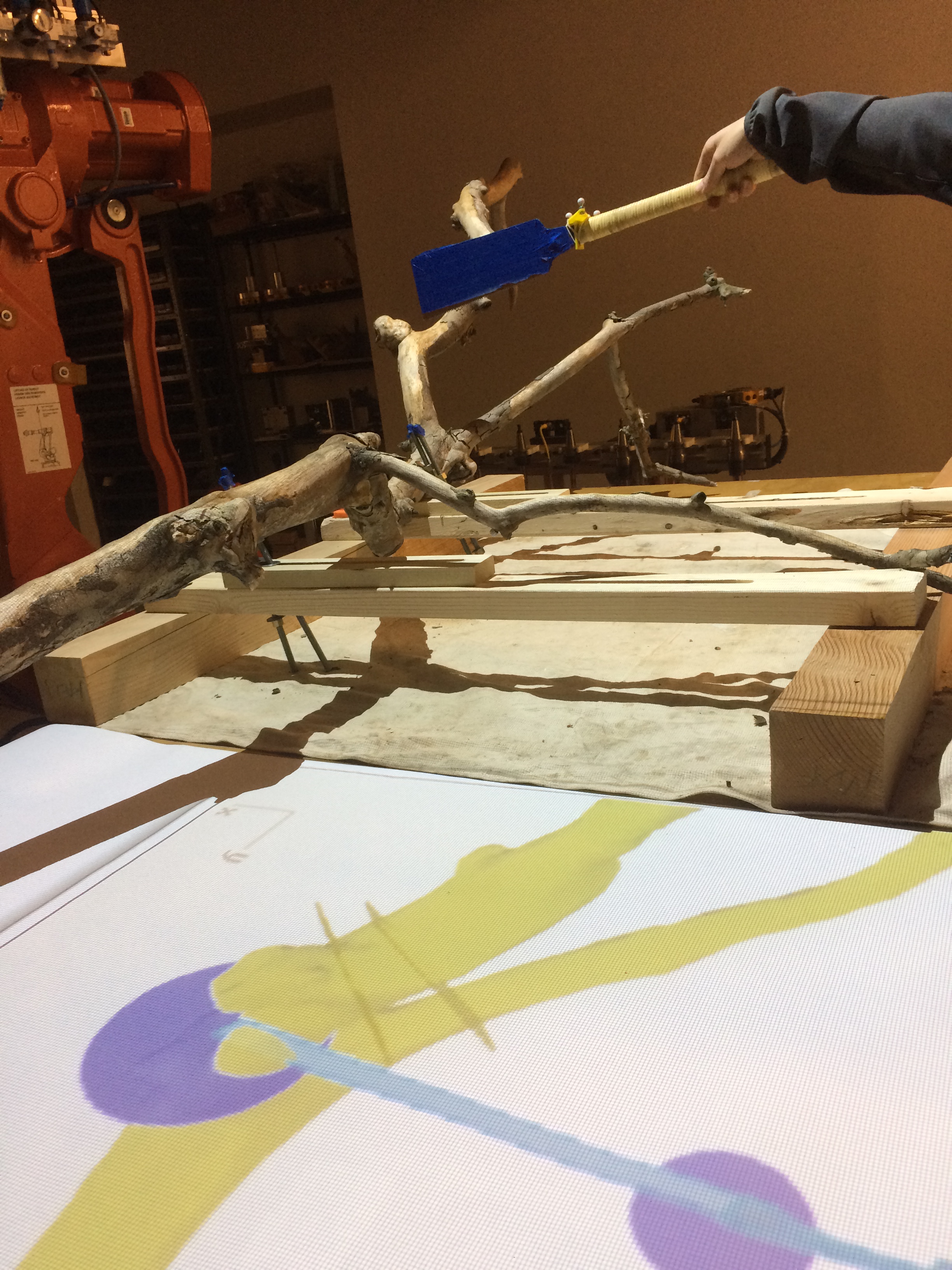
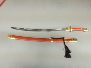
Our team focused on a particular style of Chinese martial arts called baguazhang. This technique utilizes a double-handled curved sword and dynamic movements that engage the whole body in smooth coiling and rotation. The user steps in a circular motion to build up momentum to fluidly move around an opponent and strike quickly with the sword.
Recording
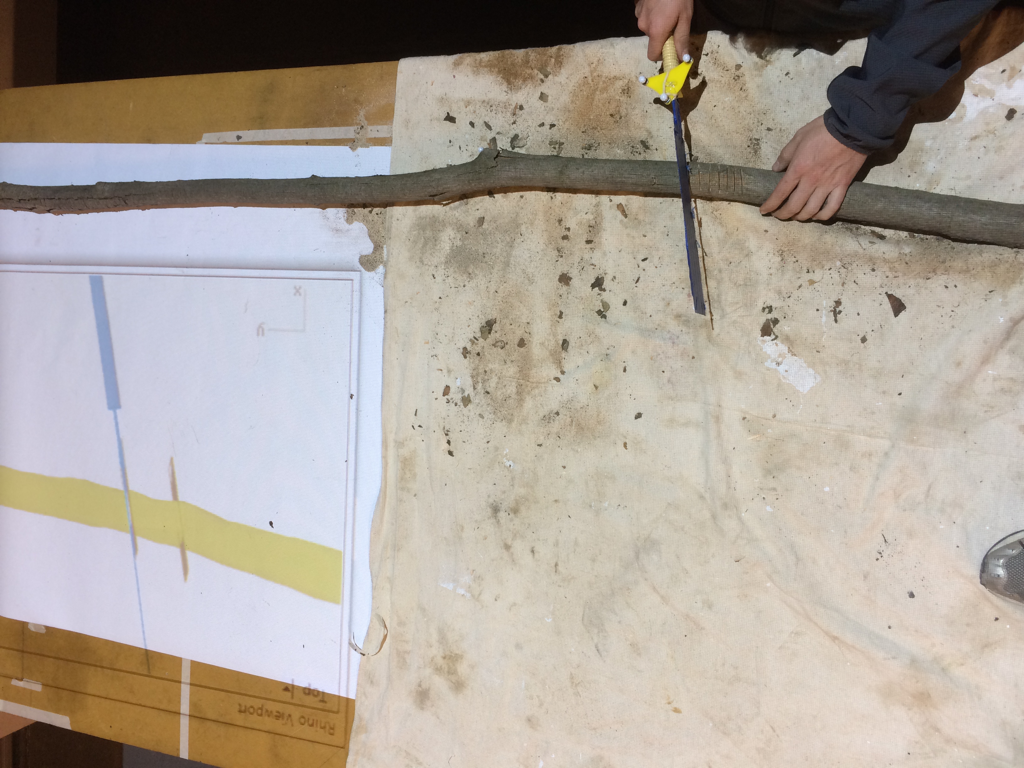
We would have loved to use skeletal tracking to record the movements of Chris’s limbs in relation to the sword, but given the time and technological constraints we decided to track only the sword’s movements. Motion tracking was a challenge given the time constraints that we had with Chris. Also, fabricating a device that would attach to the sword without slipping off or weighing down the blade was a challenge. While we originally had a more structurally sound device that would clamp onto the sword blade, we were concerned that it would be too heavy. Therefore, we rapidly prototyped an array of acrylic cutouts that adjusted to the width of the blade to be slipped onto the sword. The blade was also a reflective surface, which made recording its movements with the motion capture devices difficult.
Coding and Analysis
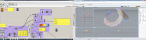
We used Grasshopper to analyze the physical forces and rotation in our recording as well as visually represent it. Because our recording was not zeroed, we had to add correctional vectors to ensure that the data was upright. Additionally, we attempted to find the centers of rotation in the data and discovered that the center was dynamic. We were unsure of its location as it kept moving, yet this provided valuable insight to how Chris was able to create ribbon-like movements in his demonstration.
Our data also maps the instantaneous velocity of the sword with color–blue indicates a slow velocity, yellow indicates medium, and red indicates fast. This shows the patterns of momentum built up over time for the sword to be swung in a fluid motion.
Artifacts
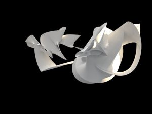

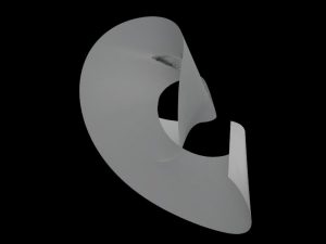
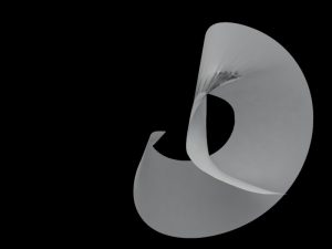
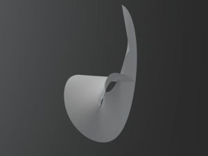
These surfaces were rendered in Rhino using V-Ray. They illustrate the movements of the sword in space as shown from the data that we had recorded.
Conclusion
While there were many flaws in our process, we were able to accurately depict the sharp and fluid motions of baguazhang through sculpture and video. Rotation and velocity were important to our understanding of how these movements came together.
Special thanks to Chris Young for demonstrating baguazhang sword movements for us!
]]>