Final Project

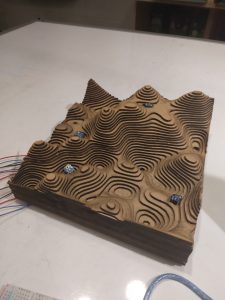
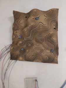
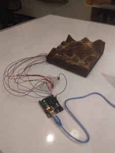
For the final project, I installed light sensors and ultrasonic sensors in and around a lasercut chipboard topography model to achieve several different objectives.
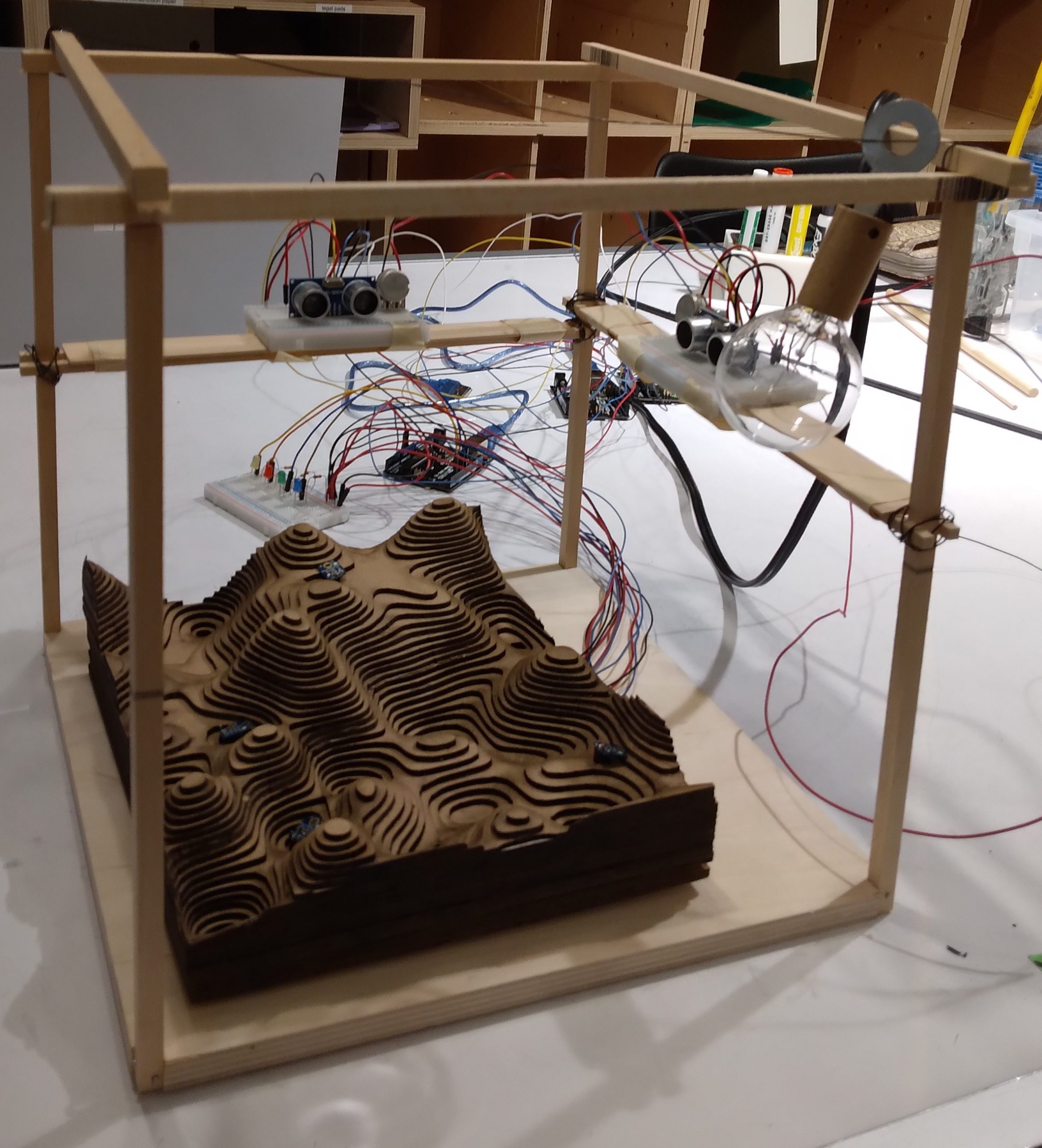
Landscape Topography Model

My final project consists of 4 parts:

  1. Visualizing Light Sensor Data on a Digital Model

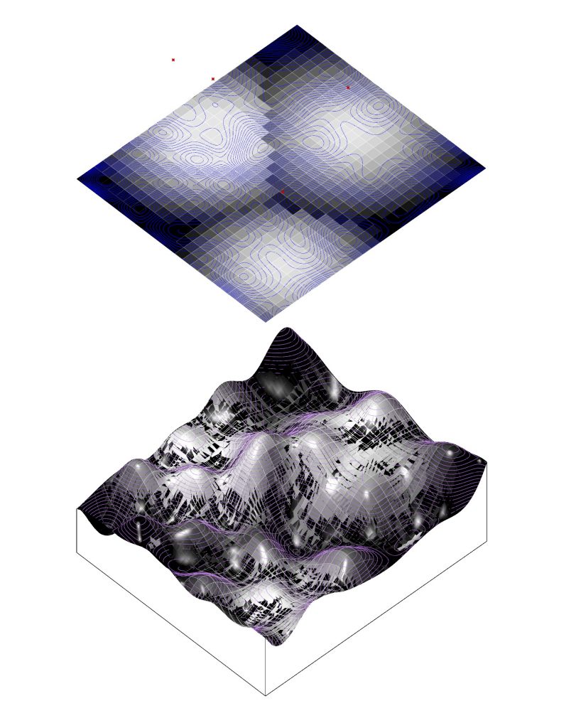
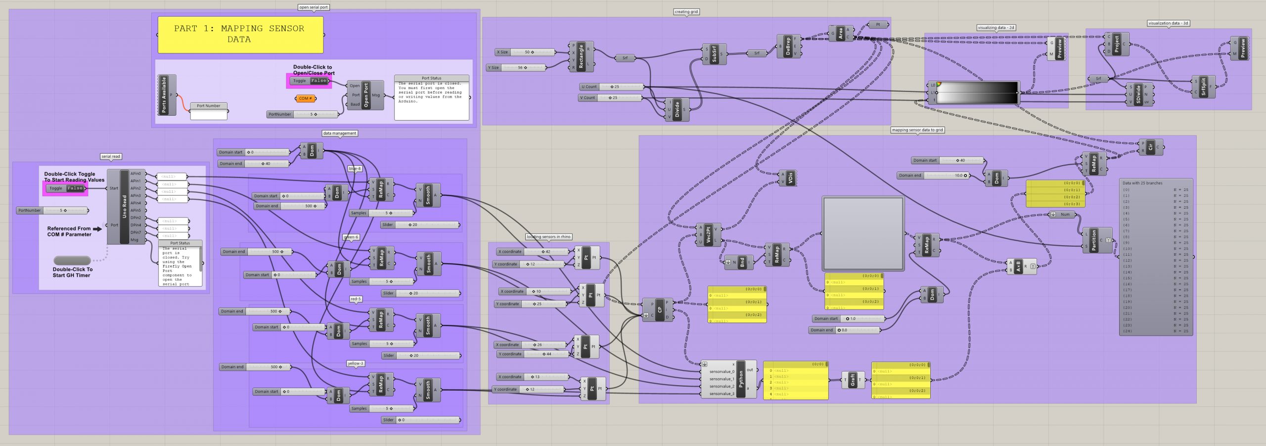
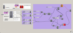
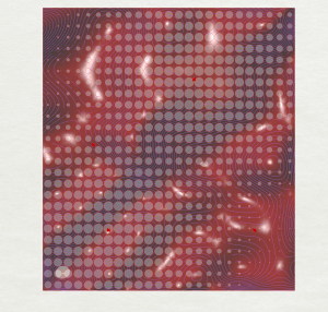
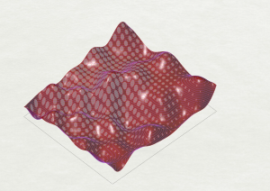
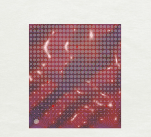
This exercise builds on previous work in the visual crit, in which data coming from light sensors influenced the visual patterns of the topography model in Rhino. In this version, light sensor data is used to create a gradient from white to black in Rhino/Grasshopper, which can either be viewed as a plan in 2d, or projected over the digital topography surface to be viewed in 3d. The data has been smoothed and remapped over a cellular grid, with data points mapped onto the digital topography model to correspond with the locations of the sensors on the physical model.

Views of 2d and 3d visualizations of the light gradient below:
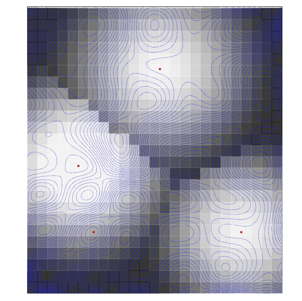
2d Visualization of Light Sensor Gradient
3d Visualization of Light Sensor Gradient


Part 1: GH Code

Demonstration of 2d visualization of light sensor data below:

2. Turning LED Lights on Below a Given Light Level

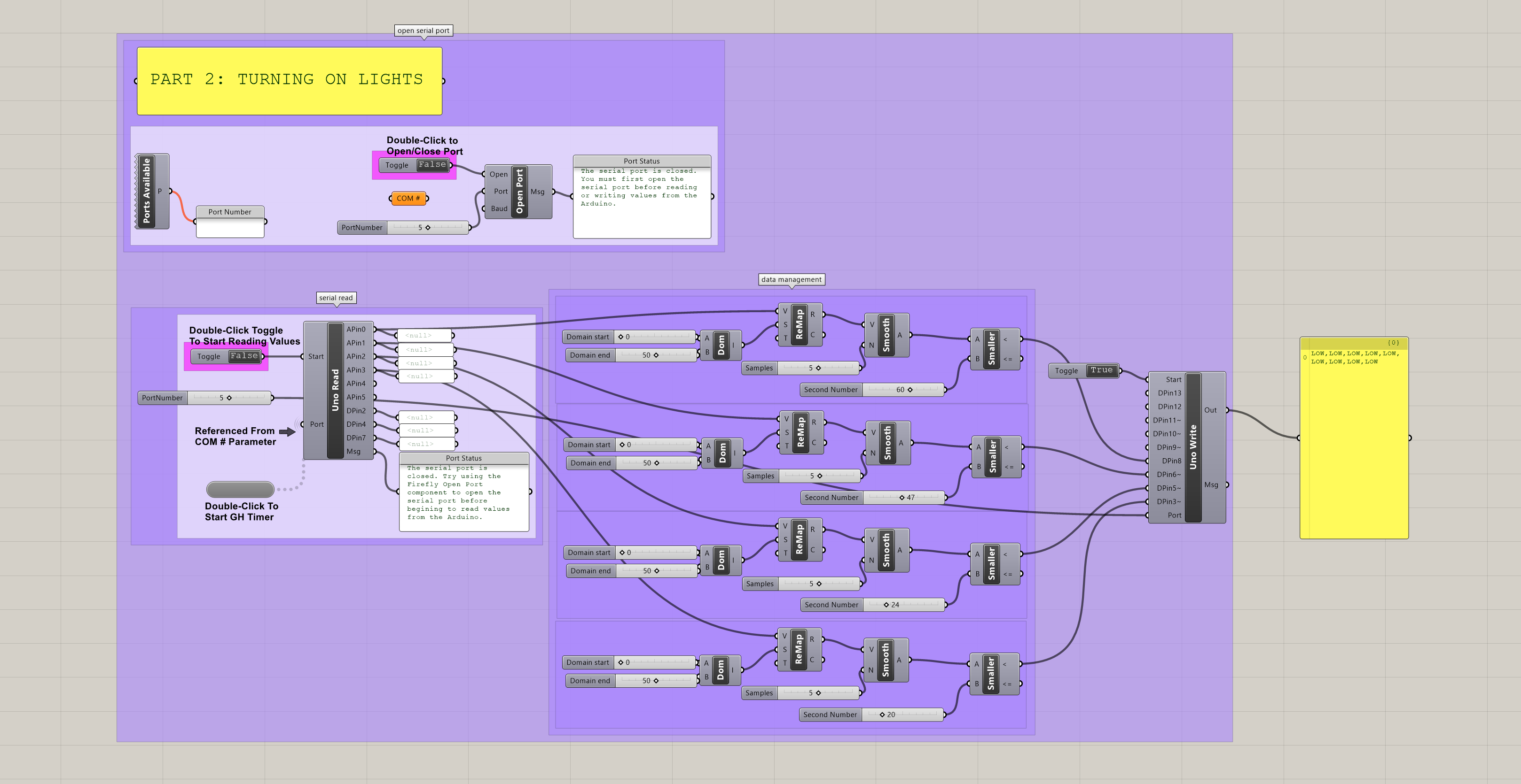
When one of the light sensors falls below a certain threshold of light, the code shown below in Grasshopper will turn on the LED light corresponding to that particular sensor. When the light sensor value rises above this threshold, the LED light turns off. Depending on the way light is cast across the physical topography, one light may be turned on due to the surrounding low light levels, while the others are off. In this way, additional light is only provided when it is deemed necessary, based on the surrounding light conditions.
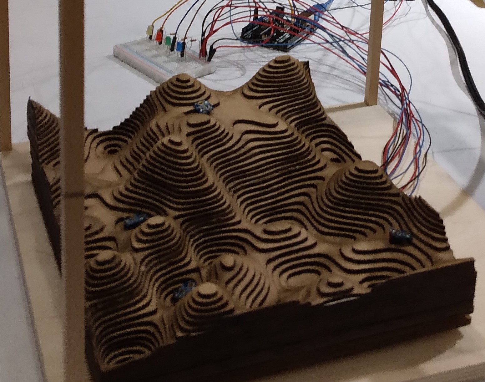
Model with mounted sensors and corresponding LED lights beyond
Part 2: GH Code

3. Digital Drawing with Ultrasonic Sensors

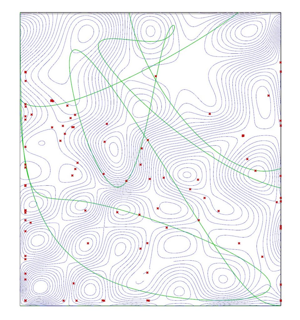
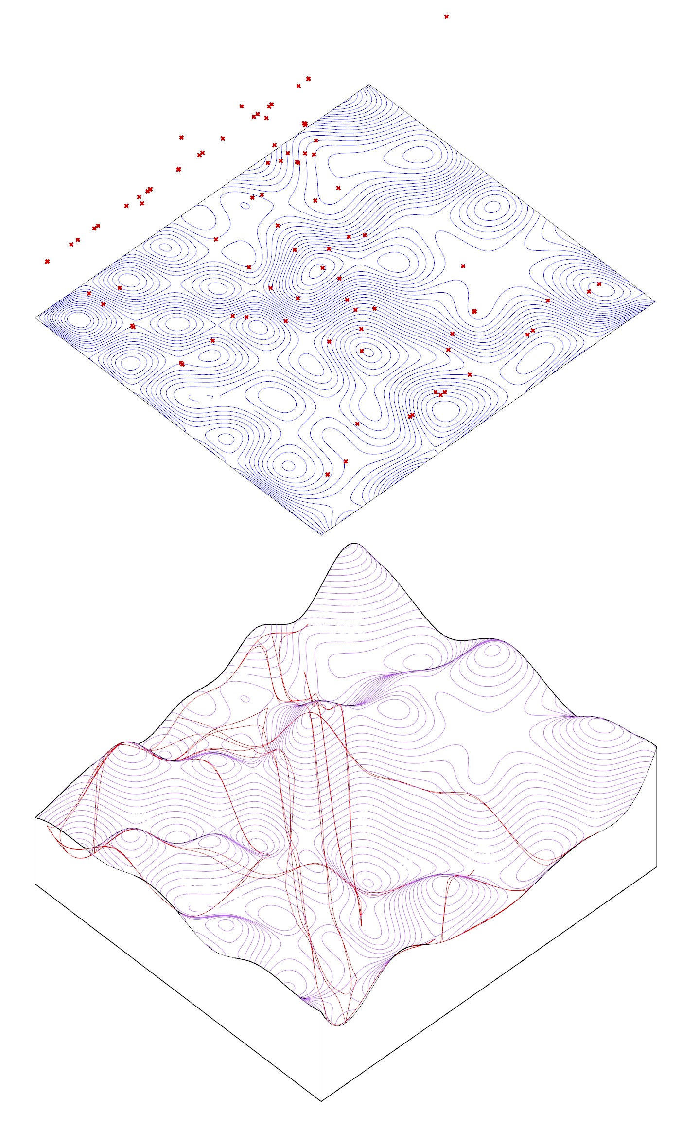
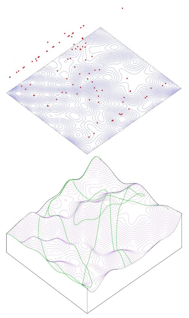
Using ultrasonic sensors mounted above the topography model, a pointer (such as a long dowel rod) can be moved across the physical terrain of the model. As the ultrasonic sensors pick up the location of the dowel, these locations are read in Grasshopper, logged, and construct points across the digital Rhino model, which can then be used to generate linework. One of the challenges with this project is the limited peripheral detection abilities of the ultrasonic sensors. Two were used in this demonstration, and when the dowel rod moved out of the range of one of the sensors, the code would interpret the coordinates in this area as “0” and the points and associated linework will “jump” to the edges of the model. One possible remedy would be to remove coordinates with “0” from the log, but this would not resolve the sensor range issue. Another possible solution could be to add more sensors. This would likely require multiple Arduinos, unless more complicated Arduino code could be developed to handle multiple ultrasonic sensors at a time (my preliminary attempts to combine 2 ultrasonic sensors on one Arduino were unsuccessful).
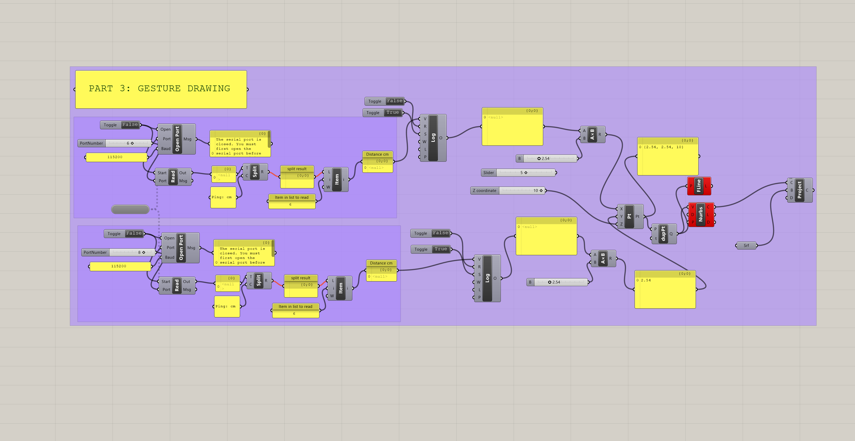
Part 3: GH Code
Ultrasonic Sketch: 3d Projection, Drawing in Green
Ultrasonic Sensors Sketch: 2d Drawing in Green
Ultrasonic Sensors Sketch: 3d Projection, Drawing in Green

4. Digital Drawing with Potentiometers

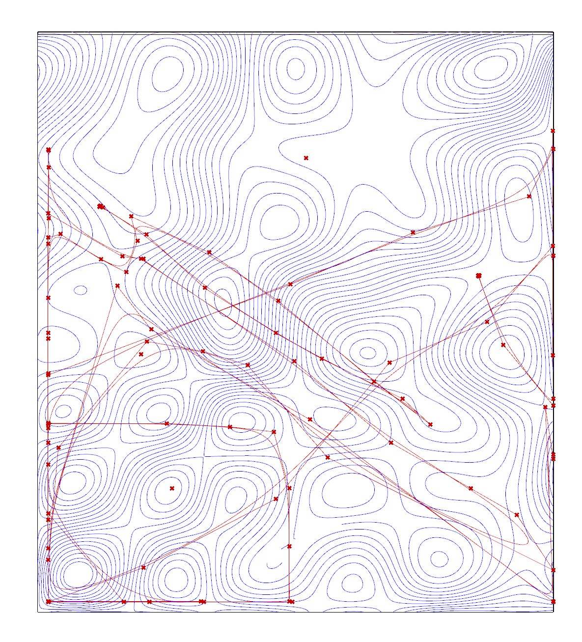
To explore a second technique for digital drawing, I used potentiometers to guide the drawing across the physical model. This method allowed for greater range and control over the digital drawing (provided one is accustomed to the controls), but it is less intuitive than gesturing with a dowel rod.
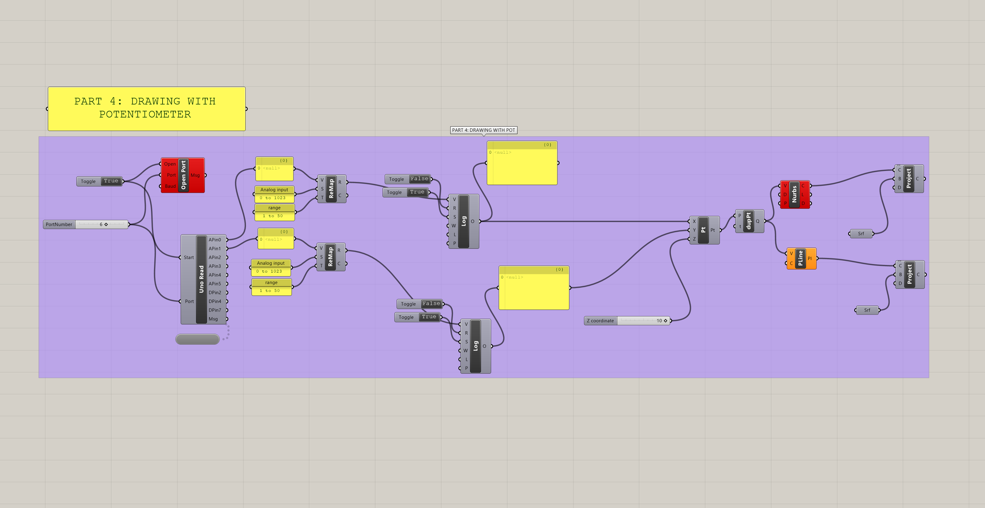
Part 4: GH Code
Drawing with Potentiometers, 2d Plan
Drawing with Potentiometers, 3d Projection

The Arduino set up for the light sensors and the potentiometer uses Firmata, written by Andrew Payne and Jason Kelly Johnson to facilitate communication between the Arduino and Rhino/Grasshopper/Firefly. A modification is required for 2022 Arduino:

/* 
 Created by Andrew Payne and Jason Kelly Johnson
 Latest Update March 25th, 2015 
 Copyright 2015 | All Rights Reserved
 version below modified for 2022 Arduino
 
 This Firmata allows you to control an Arduino board from Rhino/Grasshopper/Firefly.
 Updates, Questions, Suggestions visit: http://www.fireflyexperiments.com
 
 1. Plug Arduino boards into your USB port; confirm that your Arduino's green power LED in on
 2. Select your specific Arduino Board and Serial Port (Tools > Board; Tools > Serial Port) *Take note of your Serial Port COM #
 3. Verify (play button) and Upload (upload button) this program to your Arduino, close the Arduino program
 4. then open ... Rhino/Grasshopper/Firefly
 
 Note: The Firefly Firmata sets the following pins to perform these functions:
 
 *****ON STANDARD BOARDS (ie. Uno, Diecimila, Duemilanove, Lillypad, Mini, etc.)*****
 ANALOG IN pins 0-5 are set to return values (from 0 to 1023) for analog sensors
 DIGITAL IN pins 2,4,7 will return 0's or 1's; for 3 potential digital sensors (buttons, switches, on/off, true/false, etc.)
 DIGITAL/ANALOG OUT pins 3,5,6,11 (marked with a ~) can be used to digitalWrite, analogWrite, or Servo.write depending on the input status of that Firefly pin
 DIGITAL OUT pins 8,9,10,12,13 can be used to digitalWrite, Servo.write, or analogWrite depending on the input status of that Firefly pin
 
 *****ON MEGA BOARDS (ie. ATMEGA1280, ATMEGA2560)*****
 ANALOG IN pins 0-15 will return values (from 0 to 1023) for 16 analog sensors 
 DIGITAL IN pins 22-31 will return 0's or 1's; for digital sensors (buttons, switches, on/off, true/false, etc.) 
 DIGITAL/ANALOG OUT pins 2-13 can be used to digitalWrite, analogWrite, or Servo.write depending on the input status of that Firefly pin
 DIGITAL OUT pins 32-53 can be used to digitalWrite, Servo.write, or analogWrite depending on the input status of that Firefly pin
 
 *****ON LEONARDO BOARDS*****
 ANALOG IN pins 0-5 are set to return values (from 0 to 1023) for analog sensors
 DIGITAL IN pins 2,4,7 will return 0's or 1's; for 3 potential digital sensors (buttons, switches, on/off, true/false, etc.)
 DIGITAL/ANALOG OUT pins 3,5,6,11 (marked with a ~) can be used to digitalWrite, analogWrite, or Servo.write depending on the input status of that Firefly pin
 DIGITAL OUT pins 8,9,10,12,13 can be used to digitalWrite, Servo.write, or analogWrite depending on the input status of that Firefly pin
 
  *****ON DUE BOARDS (ie. SAM3X8E)*****
 ANALOG IN pins 0-11 will return values (from 0 to 4095) for 12 analog sensors 
 DIGITAL IN pins 22-31 will return 0's or 1's; for digital sensors (buttons, switches, on/off, true/false, etc.) 
 DIGITAL/ANALOG OUT pins 2-13 can be used to digitalWrite, analogWrite, or Servo.write depending on the input status of that Firefly pin
 DIGITAL OUT pins 32-53 can be used to digitalWrite, Servo.write, or analogWrite depending on the input status of that Firefly pin
 DAC0 and DAC1 can be used to output an analog voltage on those pins (only available on DUE boards)
 */

#include <Servo.h>            // attach Servo library (http://www.arduino.cc/playground/ComponentLib/Servo)
#include <pins_arduino.h>     // attach arduino pins header file to determine which board type is being used

#define BAUDRATE 115200       // Set the Baud Rate to an appropriate speed
#define BUFFSIZE 512          // buffer one command at a time

/*==============================================================================
 * GLOBAL VARIABLES
 *============================================================================*/

char buffer[BUFFSIZE];        // declare buffer
uint8_t bufferidx = 0;        // a type of unsigned integer of length 8 bits
char *parseptr;
char buffidx;

int counter = 0;
int numcycles = 1000;

#if defined(__AVR_ATmega328P__) || defined(__AVR_ATmega168__)                                                // declare variables for STANDARD boards
  Servo Servo13, Servo12, Servo11, Servo10, Servo9, Servo8, Servo6, Servo5, Servo3;
  Servo SERVO_CONFIG[] = {Servo13, Servo12, Servo11, Servo10, Servo9, Servo8, Servo6, Servo5, Servo3};       // declare array of Servo objects
  int WRITE_PIN_CONFIG[] = {13,12,11,10,9,8,6,5,3}; 
  int READ_APIN_CONFIG[] = {0,1,2,3,4,5};
  int READ_DPIN_CONFIG[] = {2,4,7}; 
#endif

#if defined(__AVR_ATmega32U4__) || defined(__AVR_ATmega16U4__)                                               // declare variables for LEONARDO board
  Servo Servo13, Servo12, Servo11, Servo10, Servo9, Servo8, Servo6, Servo5, Servo3;       
  Servo SERVO_CONFIG[] = {Servo13, Servo12, Servo11, Servo10, Servo9, Servo8, Servo6, Servo5, Servo3};       // declare array of Servo objects
  int WRITE_PIN_CONFIG[] = {13,12,11,10,9,8,6,5,3}; 
  int READ_APIN_CONFIG[] = {0,1,2,3,4,5};
  int READ_DPIN_CONFIG[] = {2,4,7};
#endif

#if defined(__AVR_ATmega1280__) || defined(__AVR_ATmega2560__)                        // declare variables for MEGA boards
  Servo Servo2, Servo3, Servo4, Servo5, Servo6, Servo7, Servo8, Servo9, Servo10, Servo11, Servo12, Servo13, Servo32, Servo33, Servo34, Servo35, Servo36, Servo37, Servo38, Servo39, Servo40, Servo41, Servo42, Servo43, Servo44, Servo45, Servo46, Servo47, Servo48, Servo49, Servo50, Servo51, Servo52, Servo53;
  Servo SERVO_CONFIG[] = {Servo2, Servo3, Servo4, Servo5, Servo6, Servo7, Servo8, Servo9, Servo10, Servo11, Servo12, Servo13, Servo32, Servo33, Servo34, Servo35, Servo36, Servo37, Servo38, Servo39, Servo40, Servo41, Servo42, Servo43, Servo44, Servo45, Servo46, Servo47, Servo48, Servo49, Servo50, Servo51, Servo52, Servo53};  // declare array of Servo objects
  int WRITE_PIN_CONFIG[] = {2,3,4,5,6,7,8,9,10,11,12,13,32,33,34,35,36,37,38,39,40,41,42,43,44,45,46,47,48,49,50,51,52,53}; 
  int READ_APIN_CONFIG[] = {0,1,2,3,4,5,6,7,8,9,10,11,12,13,14,15};
  int READ_DPIN_CONFIG[] = {22,23,24,25,26,27,28,29,30,31};
#endif

#if defined(__SAM3X8E__)                 // declare variables for DUE boards
  Servo FDAC0, FDAC1, Servo2, Servo3, Servo4, Servo5, Servo6, Servo7, Servo8, Servo9, Servo10, Servo11, Servo12, Servo13, Servo32, Servo33, Servo34, Servo35, Servo36, Servo37, Servo38, Servo39, Servo40, Servo41, Servo42, Servo43, Servo44, Servo45, Servo46, Servo47, Servo48, Servo49, Servo50, Servo51, Servo52, Servo53;  
  Servo SERVO_CONFIG[] = {FDAC0, FDAC1, Servo2, Servo3, Servo4, Servo5, Servo6, Servo7, Servo8, Servo9, Servo10, Servo11, Servo12, Servo13, Servo32, Servo33, Servo34, Servo35, Servo36, Servo37, Servo38, Servo39, Servo40, Servo41, Servo42, Servo43, Servo44, Servo45, Servo46, Servo47, Servo48, Servo49, Servo50, Servo51, Servo52, Servo53};  // declare array of Servo objects
  int WRITE_PIN_CONFIG[] = {0,1,2,3,4,5,6,7,8,9,10,11,12,13,32,33,34,35,36,37,38,39,40,41,42,43,44,45,46,47,48,49,50,51,52,53}; //Note: first two values correspond to the DAC pins
  int READ_APIN_CONFIG[] = {0,1,2,3,4,5,6,7,8,9,10,11};
  int READ_DPIN_CONFIG[] = {22,23,24,25,26,27,28,29,30,31};
#endif

/*==============================================================================
 * SETUP() This code runs once
 *============================================================================*/
void setup()
{ 
  Init();                       //set initial pinmodes
  Serial.begin(BAUDRATE);       // Start Serial communication
  #if defined(__SAM3X8E__)      //if the connected board is an Arduino DUE
    analogReadResolution(12);   //Set the analog read resolution to 12 bits (acceptable values between 1-32 bits).  This is only for DUE boards
    analogWriteResolution(12);  // Set the analog write resolution to 12 bits (acceptable values between 1-32 bits).  This is only for DUE boards
  #endif
}

/*==============================================================================
 * LOOP() This code loops
 *============================================================================*/
void loop()
{
  if(Serial){
    ReadSerial();                       // read and parse string from serial port and write to pins
    if (counter >= numcycles){          // Wait every nth loop 
      ReadInputs();                     // get input data and print data to the serial port
      counter = 0;                      // reset the counter
    }
    counter ++;                         // increment the writecounter
  }
}

/*==============================================================================
 * FUNCTIONS()
 *============================================================================*/

/*
* Initializes the digital pins which will be used as inputs
*/
void Init(){
  int len = sizeof(READ_DPIN_CONFIG)/sizeof(READ_DPIN_CONFIG[0]); //get the size of the array
  for(int i = 0; i < len; i++){
    pinMode(READ_DPIN_CONFIG[i], INPUT);
  }
}

/* 
* Reads the incoming ADC or digital values from the corresponding analog and digital input  
* pins and prints the value to the serial port as a formatted commma separated string
*/
void ReadInputs(){ 
  int len = sizeof(READ_APIN_CONFIG)/sizeof(READ_APIN_CONFIG[0]); //get the size of the array
  for(int i = 0; i < len; i++){
    int val = analogRead(READ_APIN_CONFIG[i]);  //read value from analog pins
    Serial.print(val); Serial.print(",");   
  }
  len = sizeof(READ_DPIN_CONFIG)/sizeof(READ_DPIN_CONFIG[0]); //get the size of the array
  for(int i = 0; i < len; i++){
    int val = digitalRead(READ_DPIN_CONFIG[i]); //read value from digital pins
    Serial.print(val); Serial.print(",");   
  }
  Serial.println("eol");  //end of line marker
}

/*
* Retrieve the latest incoming serial value and split the string at the comma delimeter.
* When a comma is found, the value is offloaded to a temporary variable and written
* to the corresponding digital pin.
*/
void ReadSerial(){
  char c;    // holds one character from the serial port
  if (Serial.available()) {
    c = Serial.read();         // read one character
    buffer[bufferidx] = c;     // add to buffer
    if (c == '\n') {  
      buffer[bufferidx+1] = 0; // terminate it
      parseptr = buffer;       // offload the buffer into temp variable
      int len = sizeof(WRITE_PIN_CONFIG)/sizeof(WRITE_PIN_CONFIG[0]); //get the size of the array
      for(int i = 0; i < len; i++){
        //parse all incoming values and assign them to the appropriate variable
        int val = parsedecimal(parseptr);       // parse the incoming number
        if(i != len - 1) parseptr = strchr(parseptr, ',')+1;   // move past the ","
        WriteToPin(WRITE_PIN_CONFIG[i], val, SERVO_CONFIG[i]);         //send value out to pin on arduino board
      }    
      bufferidx = 0;                             // reset the buffer for the next read
      return;                                    // return so that we don't trigger the index increment below
    }                                            // didn't get newline, need to read more from the buffer
    bufferidx++;                                 // increment the index for the next character
    if (bufferidx == BUFFSIZE-1) bufferidx = 0;  // if we get to the end of the buffer reset for safety
  }
}

/*
* Send the incoming value to the appropriate pin using pre-defined logic (ie. digital, analog, or servo)
*/
void WriteToPin(int _pin, int _value, Servo _servo){
  if (_value >= 10000 && _value < 20000)            // check if value should be used for Digital Write (HIGH/LOW)
  {      
    if (_servo.attached()) _servo.detach();         // detach servo is one is attached to pin
    pinMode(_pin, OUTPUT);                       
    _value -= 10000;                                // subtract 10,000 from the value sent from Grasshopper 
    if (_value == 1) digitalWrite(_pin, HIGH);     
    else digitalWrite(_pin, LOW);   
  }   
  else if (_value >= 20000 && _value < 30000)       // check if value should be used for Analog Write (0-255)
  {
    if (_servo.attached()) _servo.detach();         // detach servo is one is attached to pin
    pinMode(_pin, OUTPUT);               
    _value -= 20000;                                // subtract 20,000 from the value sent from Grasshopper
    analogWrite(_pin, _value);                     
  }
  else if (_value >= 30000 && _value < 40000)       // check if value should be used for Servo Write (0-180)
  {
    _value -= 30000;                                // subtract 30,000 from the value sent from Grasshopper
    if (!_servo.attached())_servo.attach(_pin);     // attaches a Servo to the PWM pin (180 degree standard servos)                                    
    _servo.write(_value);                          
  }
  else if (_value >= 40000 && _value < 50000)       // check if value should be used for Analog Write (0-4096) for DACs
  {
    if (_servo.attached()) _servo.detach();         // detach servo is one is attached to pin
    pinMode(_pin, OUTPUT);               
    _value -= 40000;                                // subtract 40,000 from the value sent from Grasshopper
    WriteToDAC(_pin, _value);                     
  }
}

/*
* Parse a string value as a decimal
*/
uint32_t parsedecimal(char *str){
  uint32_t d = 0;
  while (str[0] != 0) {
    if ((str[0] > '50') || (str[0] < '0'))
      return d;
    d *= 10;
    d += str[0] - '0';
    str++;
  }
  return d;
}

/*
* Send the incoming value to the appropriate DAC for DUE boards. 
* Note: analogWrite resolution (default is 12 bits) is defined in the Setup function.
*/
//modification to original sketch to work with 2022 firefly and arduino
  void WriteToDAC(int _pin, int _value){
    #if defined(__SAM3X8E__) 
    if(_pin == 0) analogWrite(DAC0, _value);
    else if (_pin == 1) analogWrite(DAC1, _value);
    #endif
  }


To use the ultrasonic sensors with Rhino/Grasshopper/Firefly, the NewPing library was used:

// ---------------------------------------------------------------------------
// Example NewPing library sketch that does a ping about 20 times per second.
// ---------------------------------------------------------------------------

#include <NewPing.h>

#define TRIGGER_PIN  12  // Arduino pin tied to trigger pin on the ultrasonic sensor.
#define ECHO_PIN     11  // Arduino pin tied to echo pin on the ultrasonic sensor.
#define MAX_DISTANCE 30 // Maximum distance we want to ping for (in centimeters). Maximum sensor distance is rated at 400-500cm.

NewPing sonar(TRIGGER_PIN, ECHO_PIN, MAX_DISTANCE); // NewPing setup of pins and maximum distance.

void setup() {
  Serial.begin(115200); // Open serial monitor at 115200 baud to see ping results.
}

void loop() {
  delay(50);                     // Wait 50ms between pings (about 20 pings/sec). 29ms should be the shortest delay between pings.
  Serial.print("Ping: ");
  Serial.print(sonar.ping_cm()); // Send ping, get distance in cm and print result (0 = outside set distance range)
  Serial.println("cm");
}
 

Crit 3: Visual

For the Visual Crit, I used Arduino, Rhino, Grasshopper, and GH plug-in Firefly to visualize sensor data over a topographical landscape. The topography model was initially generated digitally with Rhino and Grasshopper, so it could be used later in the model visualization. Contours were exported to 2d CAD to cut the physical model.

The physical model was constructed of lasercut chipboard, with enough variation in height to imitate a landscape that could plausibly have multiple microclimates, which can form due to differences in light, drainage, and airflow. Changes in topography can drive these shifts in environmental conditions. Light sensors will installed in different areas of the model.

Uploaded to the arduino is this Firmata code (which has been edited since the 2015 version to account for some differences in Arduino):

/* 
 Created by Andrew Payne and Jason Kelly Johnson
 Latest Update March 25th, 2015 
 Copyright 2015 | All Rights Reserved
 
 This Firmata allows you to control an Arduino board from Rhino/Grasshopper/Firefly.
 Updates, Questions, Suggestions visit: http://www.fireflyexperiments.com
 
 1. Plug Arduino boards into your USB port; confirm that your Arduino's green power LED in on
 2. Select your specific Arduino Board and Serial Port (Tools > Board; Tools > Serial Port) *Take note of your Serial Port COM #
 3. Verify (play button) and Upload (upload button) this program to your Arduino, close the Arduino program
 4. then open ... Rhino/Grasshopper/Firefly
 
 Note: The Firefly Firmata sets the following pins to perform these functions:
 
 *****ON STANDARD BOARDS (ie. Uno, Diecimila, Duemilanove, Lillypad, Mini, etc.)*****
 ANALOG IN pins 0-5 are set to return values (from 0 to 1023) for analog sensors
 DIGITAL IN pins 2,4,7 will return 0's or 1's; for 3 potential digital sensors (buttons, switches, on/off, true/false, etc.)
 DIGITAL/ANALOG OUT pins 3,5,6,11 (marked with a ~) can be used to digitalWrite, analogWrite, or Servo.write depending on the input status of that Firefly pin
 DIGITAL OUT pins 8,9,10,12,13 can be used to digitalWrite, Servo.write, or analogWrite depending on the input status of that Firefly pin
 
 *****ON MEGA BOARDS (ie. ATMEGA1280, ATMEGA2560)*****
 ANALOG IN pins 0-15 will return values (from 0 to 1023) for 16 analog sensors 
 DIGITAL IN pins 22-31 will return 0's or 1's; for digital sensors (buttons, switches, on/off, true/false, etc.) 
 DIGITAL/ANALOG OUT pins 2-13 can be used to digitalWrite, analogWrite, or Servo.write depending on the input status of that Firefly pin
 DIGITAL OUT pins 32-53 can be used to digitalWrite, Servo.write, or analogWrite depending on the input status of that Firefly pin
 
 *****ON LEONARDO BOARDS*****
 ANALOG IN pins 0-5 are set to return values (from 0 to 1023) for analog sensors
 DIGITAL IN pins 2,4,7 will return 0's or 1's; for 3 potential digital sensors (buttons, switches, on/off, true/false, etc.)
 DIGITAL/ANALOG OUT pins 3,5,6,11 (marked with a ~) can be used to digitalWrite, analogWrite, or Servo.write depending on the input status of that Firefly pin
 DIGITAL OUT pins 8,9,10,12,13 can be used to digitalWrite, Servo.write, or analogWrite depending on the input status of that Firefly pin
 
  *****ON DUE BOARDS (ie. SAM3X8E)*****
 ANALOG IN pins 0-11 will return values (from 0 to 4095) for 12 analog sensors 
 DIGITAL IN pins 22-31 will return 0's or 1's; for digital sensors (buttons, switches, on/off, true/false, etc.) 
 DIGITAL/ANALOG OUT pins 2-13 can be used to digitalWrite, analogWrite, or Servo.write depending on the input status of that Firefly pin
 DIGITAL OUT pins 32-53 can be used to digitalWrite, Servo.write, or analogWrite depending on the input status of that Firefly pin
 DAC0 and DAC1 can be used to output an analog voltage on those pins (only available on DUE boards)
 */

#include <Servo.h>            // attach Servo library (http://www.arduino.cc/playground/ComponentLib/Servo)
#include <pins_arduino.h>     // attach arduino pins header file to determine which board type is being used

#define BAUDRATE 115200       // Set the Baud Rate to an appropriate speed
#define BUFFSIZE 512          // buffer one command at a time

/*==============================================================================
 * GLOBAL VARIABLES
 *============================================================================*/

char buffer[BUFFSIZE];        // declare buffer
uint8_t bufferidx = 0;        // a type of unsigned integer of length 8 bits
char *parseptr;
char buffidx;

int counter = 0;
int numcycles = 1000;

#if defined(__AVR_ATmega328P__) || defined(__AVR_ATmega168__)                                                // declare variables for STANDARD boards
  Servo Servo13, Servo12, Servo11, Servo10, Servo9, Servo8, Servo6, Servo5, Servo3;
  Servo SERVO_CONFIG[] = {Servo13, Servo12, Servo11, Servo10, Servo9, Servo8, Servo6, Servo5, Servo3};       // declare array of Servo objects
  int WRITE_PIN_CONFIG[] = {13,12,11,10,9,8,6,5,3}; 
  int READ_APIN_CONFIG[] = {0,1,2,3,4,5};
  int READ_DPIN_CONFIG[] = {2,4,7}; 
#endif

#if defined(__AVR_ATmega32U4__) || defined(__AVR_ATmega16U4__)                                               // declare variables for LEONARDO board
  Servo Servo13, Servo12, Servo11, Servo10, Servo9, Servo8, Servo6, Servo5, Servo3;       
  Servo SERVO_CONFIG[] = {Servo13, Servo12, Servo11, Servo10, Servo9, Servo8, Servo6, Servo5, Servo3};       // declare array of Servo objects
  int WRITE_PIN_CONFIG[] = {13,12,11,10,9,8,6,5,3}; 
  int READ_APIN_CONFIG[] = {0,1,2,3,4,5};
  int READ_DPIN_CONFIG[] = {2,4,7};
#endif

#if defined(__AVR_ATmega1280__) || defined(__AVR_ATmega2560__)                        // declare variables for MEGA boards
  Servo Servo2, Servo3, Servo4, Servo5, Servo6, Servo7, Servo8, Servo9, Servo10, Servo11, Servo12, Servo13, Servo32, Servo33, Servo34, Servo35, Servo36, Servo37, Servo38, Servo39, Servo40, Servo41, Servo42, Servo43, Servo44, Servo45, Servo46, Servo47, Servo48, Servo49, Servo50, Servo51, Servo52, Servo53;
  Servo SERVO_CONFIG[] = {Servo2, Servo3, Servo4, Servo5, Servo6, Servo7, Servo8, Servo9, Servo10, Servo11, Servo12, Servo13, Servo32, Servo33, Servo34, Servo35, Servo36, Servo37, Servo38, Servo39, Servo40, Servo41, Servo42, Servo43, Servo44, Servo45, Servo46, Servo47, Servo48, Servo49, Servo50, Servo51, Servo52, Servo53};  // declare array of Servo objects
  int WRITE_PIN_CONFIG[] = {2,3,4,5,6,7,8,9,10,11,12,13,32,33,34,35,36,37,38,39,40,41,42,43,44,45,46,47,48,49,50,51,52,53}; 
  int READ_APIN_CONFIG[] = {0,1,2,3,4,5,6,7,8,9,10,11,12,13,14,15};
  int READ_DPIN_CONFIG[] = {22,23,24,25,26,27,28,29,30,31};
#endif

#if defined(__SAM3X8E__)                 // declare variables for DUE boards
  Servo FDAC0, FDAC1, Servo2, Servo3, Servo4, Servo5, Servo6, Servo7, Servo8, Servo9, Servo10, Servo11, Servo12, Servo13, Servo32, Servo33, Servo34, Servo35, Servo36, Servo37, Servo38, Servo39, Servo40, Servo41, Servo42, Servo43, Servo44, Servo45, Servo46, Servo47, Servo48, Servo49, Servo50, Servo51, Servo52, Servo53;  
  Servo SERVO_CONFIG[] = {FDAC0, FDAC1, Servo2, Servo3, Servo4, Servo5, Servo6, Servo7, Servo8, Servo9, Servo10, Servo11, Servo12, Servo13, Servo32, Servo33, Servo34, Servo35, Servo36, Servo37, Servo38, Servo39, Servo40, Servo41, Servo42, Servo43, Servo44, Servo45, Servo46, Servo47, Servo48, Servo49, Servo50, Servo51, Servo52, Servo53};  // declare array of Servo objects
  int WRITE_PIN_CONFIG[] = {0,1,2,3,4,5,6,7,8,9,10,11,12,13,32,33,34,35,36,37,38,39,40,41,42,43,44,45,46,47,48,49,50,51,52,53}; //Note: first two values correspond to the DAC pins
  int READ_APIN_CONFIG[] = {0,1,2,3,4,5,6,7,8,9,10,11};
  int READ_DPIN_CONFIG[] = {22,23,24,25,26,27,28,29,30,31};
#endif

/*==============================================================================
 * SETUP() This code runs once
 *============================================================================*/
void setup()
{ 
  Init();                       //set initial pinmodes
  Serial.begin(BAUDRATE);       // Start Serial communication
  #if defined(__SAM3X8E__)      //if the connected board is an Arduino DUE
    analogReadResolution(12);   //Set the analog read resolution to 12 bits (acceptable values between 1-32 bits).  This is only for DUE boards
    analogWriteResolution(12);  // Set the analog write resolution to 12 bits (acceptable values between 1-32 bits).  This is only for DUE boards
  #endif
}

/*==============================================================================
 * LOOP() This code loops
 *============================================================================*/
void loop()
{
  if(Serial){
    ReadSerial();                       // read and parse string from serial port and write to pins
    if (counter >= numcycles){          // Wait every nth loop 
      ReadInputs();                     // get input data and print data to the serial port
      counter = 0;                      // reset the counter
    }
    counter ++;                         // increment the writecounter
  }
}

/*==============================================================================
 * FUNCTIONS()
 *============================================================================*/

/*
* Initializes the digital pins which will be used as inputs
*/
void Init(){
  int len = sizeof(READ_DPIN_CONFIG)/sizeof(READ_DPIN_CONFIG[0]); //get the size of the array
  for(int i = 0; i < len; i++){
    pinMode(READ_DPIN_CONFIG[i], INPUT);
  }
}

/* 
* Reads the incoming ADC or digital values from the corresponding analog and digital input  
* pins and prints the value to the serial port as a formatted commma separated string
*/
void ReadInputs(){ 
  int len = sizeof(READ_APIN_CONFIG)/sizeof(READ_APIN_CONFIG[0]); //get the size of the array
  for(int i = 0; i < len; i++){
    int val = analogRead(READ_APIN_CONFIG[i]);  //read value from analog pins
    Serial.print(val); Serial.print(",");   
  }
  len = sizeof(READ_DPIN_CONFIG)/sizeof(READ_DPIN_CONFIG[0]); //get the size of the array
  for(int i = 0; i < len; i++){
    int val = digitalRead(READ_DPIN_CONFIG[i]); //read value from digital pins
    Serial.print(val); Serial.print(",");   
  }
  Serial.println("eol");  //end of line marker
}

/*
* Retrieve the latest incoming serial value and split the string at the comma delimeter.
* When a comma is found, the value is offloaded to a temporary variable and written
* to the corresponding digital pin.
*/
void ReadSerial(){
  char c;    // holds one character from the serial port
  if (Serial.available()) {
    c = Serial.read();         // read one character
    buffer[bufferidx] = c;     // add to buffer
    if (c == '\n') {  
      buffer[bufferidx+1] = 0; // terminate it
      parseptr = buffer;       // offload the buffer into temp variable
      int len = sizeof(WRITE_PIN_CONFIG)/sizeof(WRITE_PIN_CONFIG[0]); //get the size of the array
      for(int i = 0; i < len; i++){
        //parse all incoming values and assign them to the appropriate variable
        int val = parsedecimal(parseptr);       // parse the incoming number
        if(i != len - 1) parseptr = strchr(parseptr, ',')+1;   // move past the ","
        WriteToPin(WRITE_PIN_CONFIG[i], val, SERVO_CONFIG[i]);         //send value out to pin on arduino board
      }    
      bufferidx = 0;                             // reset the buffer for the next read
      return;                                    // return so that we don't trigger the index increment below
    }                                            // didn't get newline, need to read more from the buffer
    bufferidx++;                                 // increment the index for the next character
    if (bufferidx == BUFFSIZE-1) bufferidx = 0;  // if we get to the end of the buffer reset for safety
  }
}

/*
* Send the incoming value to the appropriate pin using pre-defined logic (ie. digital, analog, or servo)
*/
void WriteToPin(int _pin, int _value, Servo _servo){
  if (_value >= 10000 && _value < 20000)            // check if value should be used for Digital Write (HIGH/LOW)
  {      
    if (_servo.attached()) _servo.detach();         // detach servo is one is attached to pin
    pinMode(_pin, OUTPUT);                       
    _value -= 10000;                                // subtract 10,000 from the value sent from Grasshopper 
    if (_value == 1) digitalWrite(_pin, HIGH);     
    else digitalWrite(_pin, LOW);   
  }   
  else if (_value >= 20000 && _value < 30000)       // check if value should be used for Analog Write (0-255)
  {
    if (_servo.attached()) _servo.detach();         // detach servo is one is attached to pin
    pinMode(_pin, OUTPUT);               
    _value -= 20000;                                // subtract 20,000 from the value sent from Grasshopper
    analogWrite(_pin, _value);                     
  }
  else if (_value >= 30000 && _value < 40000)       // check if value should be used for Servo Write (0-180)
  {
    _value -= 30000;                                // subtract 30,000 from the value sent from Grasshopper
    if (!_servo.attached())_servo.attach(_pin);     // attaches a Servo to the PWM pin (180 degree standard servos)                                    
    _servo.write(_value);                          
  }
  else if (_value >= 40000 && _value < 50000)       // check if value should be used for Analog Write (0-4096) for DACs
  {
    if (_servo.attached()) _servo.detach();         // detach servo is one is attached to pin
    pinMode(_pin, OUTPUT);               
    _value -= 40000;                                // subtract 40,000 from the value sent from Grasshopper
    WriteToDAC(_pin, _value);                     
  }
}

/*
* Parse a string value as a decimal
*/
uint32_t parsedecimal(char *str){
  uint32_t d = 0;
  while (str[0] != 0) {
    if ((str[0] > '50') || (str[0] < '0'))
      return d;
    d *= 10;
    d += str[0] - '0';
    str++;
  }
  return d;
}

/*
* Send the incoming value to the appropriate DAC for DUE boards. 
* Note: analogWrite resolution (default is 12 bits) is defined in the Setup function.
*/
//modification to original sketch to work with 2022 firefly and arduino
  void WriteToDAC(int _pin, int _value){
    #if defined(__SAM3X8E__) 
    if(_pin == 0) analogWrite(DAC0, _value);
    else if (_pin == 1) analogWrite(DAC1, _value);
    #endif
  }

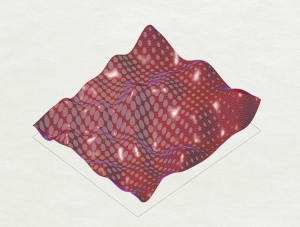
Next, with Grasshopper/Firefly, the serial data from the light sensors is read. This data is used to generate points, which act as attractors in a domain field. The brighter the light, the smaller the circle illustrated in the domain field.

The final results can be viewed as a plan, or project onto the digital model surface to be viewed in 3d.

Light Readings, plan view, v1

Light Readings, 3d, v1

Light Readings, plan view, v2

Light Readings, plan view, v2


FootprintID and Mapping Frequencies in Matlab from Audio Files

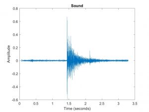
In one of my other courses (Foundations of Intelligent Infrastructure), we went through an exercise today where we recorded sound and then used Matlab to map frequencies.

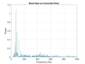
My group measured the sound of different shoes stomping on the concrete hall in Porter. Graphs showing frequency and sound below.

Our experiment reminded the professor of a project at CMU where floor sensors are used to measure movement across spaces. The specific application discussed is in elder care, but also may be a way to provide less invasive monitoring of spaces.

https://www.cmu.edu/piper/news/archives/2017/february/noh-wins-NSF-award.html

https://www.andrew.cmu.edu/user/shijiapa/documentations/Pan_Ubicomp_2017.pdf


Matlab code (note: need to drop sound file into the same folder as the Matlab file):

%%
clear all; clc;

% Load signal in the time domain, x (fs is the sample rate in hertz)
[x,fs] = audioread('takeone.m4a');
tb = (0:1/fs:(length(x)-1)/fs); % Convert samples, k, to time base, t
plot(tb,x)
xlabel('Time (seconds)')
ylabel('Amplitude')
title('Sound')

%% 
% Play the sound
sound(x,fs)

%%
% Use the fft command to compute the DFT of the signal. 
m = length(x);         % Window length, N
y = fft(x,m);          % DFT of signal
f = (0:m-1)*(fs/m);    % Frequency range
p = y.*conj(y)/m;      % Power of the DFT

% Plot up to the Nyquist frequency:
plot(f(1:floor(m/2)),p(1:floor(m/2)))
xlabel('Frequency (Hz)')
ylabel('Power')
title('Five Shoe Stomps on Concrete Floor')
grid on;
xlim([0 1000])        % Zoom in on relevant range


Gestures to control Holograms (within limits)

We talked about how tiring gestural interfaces can be in class. I came across this project – the Holographic Theater- by Simmetrico while looking for some interactive design examples. I think it’s interesting that they choose to limit the gestures to a ‘portal’ area- maybe this kind of ‘area limit’ could support a type of ergonomics for gestural interfaces: https://www.leva.io/projects/holographic-theater

RUSSIAN COPPER COMPANY’S PAVILION 2019


Assignment: Visual

The assignment is two parts- one, reading chapters 3-5 in Make It So, and two, examples of good and bad visuals.


Readings

Chapter 3: Visual Interfaces

The authors discuss visuals in the context of user interfaces and controls, identifying cinematic cliches such as the heavy use of blue glow, transparencies, and circular screens to suggest futuristic technology. The drivers coming from the needs of film include post-production work, legibility (movie watchers can only read so much text on a screen so fast), and narratives (communicating additional information about the scenario or cultures of of the users, dramatic tension, attractive/entertaining visuals for audiences).

Chapter 4: Volumetric Projection

The volumetric projection, aka projections of massless, moving 3d imagery, is used as a futuristic means of communicating, despite various practical drawbacks (need for stealth/privacy, and need for sorting out eye contact).. Authors address that 2d information representation may be better than 3d and challenges with VP, including that past VP remains very similar across time, and that deviating from the tried-and-true qualities may lead to confusing and failure to fulfill audience expectations.

Chapter 5: Gesture

The authors discuss examples of using gestures to provide input  to a system and challenges associated with their use, given that gestural interface systems need to understand intent and need to be able to be manipulated to do a variety of tasks, many of which are abstract. Minority Report, which we discussed in class, was referenced. The authors list 7 major gestures used in Hollywood, which are intuitive to our understanding of working with tactile objects in the real world (the book says pinch and spread for scaling has no physical analog, but it is very commonly used today for the manipulation of touchscreens). They discuss the limitations of a ‘natural’ user interface working off of gestures- also, in class, we discuss how gestures can differ between cultures, even for gestures that we may consider ‘natural.’

Good and Bad Visuals

Unusual Stop Sign: On my commute, there is a stop sign at a mostly L-intersection that had a second sign beneath it saying “Except for Right Turn” – meaning that those approaching the  T can turn. It is located at a unique condition, where the L-intersection has a fenced off road to one side (which gives it the look of a T-intersection). Given that the area is a bottleneck, this sign encourages that traffic continues to flow, especially since it seems the majority of people do turn right. I have thought it was weird since I first saw it, but I cannot think of a better way to communicate to drivers. It is good to show the STOP, in case the driver is turning left. Then, as the driver prepares to stop, they read “except for right turn” and those turning right keep moving.

3d or 2d: We had a seminar presentation about modelling hazards and infrastructural risks in the event of natural disasters. One student asked the presenter about 3d modelling and topography, and the presenter showed an example of using 3d, but also said that when one works with data in 3d (4d, really, if we are considering time as an integral dimension to these predictive models), the computational lag is so great that it cannot perform under the tight time constraints sometimes needed for natural disaster risk assessment and disaster response. Therefore, working in 3d may actually not be suitable or appropriate, depending on the scope and scale of the problem.

Crit 2: Sound

This project uses a color sensor (TCS34725) to determine whether or not a banana is ripe. The sketch includes a button for the user to press when ready to evaluate the banana. One series of beeps indicates the banana is ready to eat, another series indicates the banana is not ready to eat. Since there is a data smoothing component, there is also a noise that identifies when new readings are dramatically different from the average reading, and notifies the user that the sensor is still calculating.

#include <Wire.h>
#include "Adafruit_TCS34725.h"

/* Example code for the Adafruit TCS34725 breakout library */

/* Connect SCL    to analog 5
   Connect SDA    to analog 4
   Connect VDD    to 3.3V DC
   Connect GROUND to common ground */

/* Initialise with default values (int time = 2.4ms, gain = 1x) */
Adafruit_TCS34725 tcs = Adafruit_TCS34725();

//* Initialise with specific int time and gain values *
//Adafruit_TCS34725 tcs = Adafruit_TCS34725(TCS34725_INTEGRATIONTIME_500MS, TCS34725_GAIN_1X);

int speakerpin=8;
int buttonpin=2;


// data smoothing
const int numReadings = 10;

int readings[numReadings];      // the readings from the analog input
int readIndex = 0;              // the index of the current reading
int total = 0;                  // the running total
int averageb = 0;                // the average


void setup(void) {
  Serial.begin(9600);
  for (int thisReading = 0; thisReading < numReadings; thisReading++) {
    readings[thisReading] = 0;
  }

  pinMode(buttonpin,INPUT_PULLUP);

  if (tcs.begin()) {
    Serial.println("Found sensor");
  } else {
    Serial.println("No TCS34725 found ... check your connections");
    while (1);
  }

  // Now we're ready to get readings!
}

void loop(void) {
  uint16_t r, g, b, c, colorTemp, lux;

  tcs.getRawData(&r, &g, &b, &c);
  // colorTemp = tcs.calculateColorTemperature(r, g, b);
  colorTemp = tcs.calculateColorTemperature_dn40(r, g, b, c);
  lux = tcs.calculateLux(r, g, b);


    // subtract the last reading:
  total = total - readings[readIndex];
  // read from the sensor:
  readings[readIndex] = b;
  Serial.println(b);
  // add the reading to the total:
  total = total + readings[readIndex];
  // advance to the next position in the array:
  readIndex = readIndex + 1;

  // if we're at the end of the array...
  if (readIndex >= numReadings) {
    // ...wrap around to the beginning:
    readIndex = 0;
  }

  // calculate the average:
  averageb = total / numReadings;
  // send it to the computer as ASCII digits
  Serial.println(averageb);
  delay(1);        // delay in between reads for stability


  Serial.print("Color Temp: "); Serial.print(colorTemp, DEC); Serial.print(" K - ");
  Serial.print("Lux: "); Serial.print(lux, DEC); Serial.print(" - ");
  Serial.print("R: "); Serial.print(r, DEC); Serial.print(" ");
  Serial.print("G: "); Serial.print(g, DEC); Serial.print(" ");
  Serial.print("B: "); Serial.print(b, DEC); Serial.print(" ");
  Serial.print("C: "); Serial.print(c, DEC); Serial.print(" ");
  Serial.println(" ");
delay(100); delay(100);   delay(100);   

  int buttonvalue=digitalRead(buttonpin);
  Serial.println(buttonvalue);

  if (buttonvalue == HIGH) {
    Serial.println("button is pressed");
    if (averageb>=20){
      Serial.println("not ready");
      tone(speakerpin,293.66,1000);
      delay(1000);
      noTone(speakerpin);
      delay(500);
      tone(speakerpin,293.66,1000);
      delay(1000);
      noTone(speakerpin);
    } else if (b-averageb>=10) {
      Serial.println("calculating");
      tone(speakerpin,200,500);
      delay(500);
      noTone(speakerpin);
      delay(500);
    } else {
      Serial.println("ready to eat");
      tone(speakerpin,329.63,250);
      delay(250);
      noTone(speakerpin);
      delay(250);
      tone(speakerpin,311.13,250);
      noTone(speakerpin);
      delay(1000);
      tone(speakerpin,329.63,1000);
      noTone(speakerpin);
      delay(1000);
      }

  } else {
    Serial.println("button is not pressed");
  }


}


Piano Visualizer: Combining Sound and Visualization

These have become popular on my Youtube suggestions list:

There are multiple resources for piano visualization. They can be mesmerizing to watch. They are also used for interactive, remote piano instruction. When I started playing piano again after about 15 years, I found that videos were more helpful than sheet music (which I had to re-remember how to read).

https://piano-visualizer.com/home

Assignment 7: Sound with Meaning

To develop ‘sound with meaning,’ I wrote a sketch using the tone() function to replicate the ‘wah wah wah’ trombone sound. Sketch and video below.


void setup() {

  tone(7, 293.66, 1000);
  delay(1000);
  noTone(7);
  delay(500);
  tone(7,277.18,1000);
  delay(1000);
  noTone(7);
  delay(500);
  tone(7,261.63,1000);
  delay(1000);
  noTone(7);
  delay(500);
  tone(7,246.94,3000);
  delay(1500);
  noTone(7);
  delay(3000);
}

void loop() {


}


I had a 60 hertz hum with the original power supply I used the first time around. Switching to another power reduced the issue, but it’s still there.

Resources

More background on the Teensy audio library and MQS:

https://melp242.blogspot.com/2020/10/audio-output-on-teensy-4x-boards.html

Note frequencies:

https://pages.mtu.edu/~suits/notefreqs.html

Reading Assignment: Make It So, 3/17

Reading assignment: Chapters 6 and 10 Of Make it So

Chapter 6: Sonic Interfaces

The authors establish 2 major categories for sonic interfaces: sonic output and voice interfaces. The chapter covers outputs including considerations for effects such as alarms, ambient sound such as buzzing or clattering made by machinery, and directional sound. Topics around interfaces deal with music and multiple types of voice interfaces, including more sophisticated conversational interfaces. I agree that the more sophisticated the voice interface, the more that is expected out of it (for example, when dealing with the automated voice when calling insurance or the bank).  Still, I’m surprised that there still is not a feature that allows automated systems to measure how annoyed a person is getting with the system (for example, syllables becoming more terse, or volume increasing) and getting the caller over to a human associate as quickly as possible. Perhaps everyone gets terse and annoyed, so there’s no need to measure it, or rank people by the amount that the automated system annoys them.

—-

Chapter 10: Communication

I was interested to see authors using terms “asynchronous” and “synchronous,” which I’m sure have been used in discussions around communication for a long time, but I only started seeing that term at the start of COVID-19 to make a distinction between a zoom call and a zoom recording. The chapter identifies the functions needed in both categories of communication: composing, playback, activation, connecting between caller and receiver, connection monitoring, ending a call. Other considerations addressed include volume control, accompanying visuals/video, mute functions, language translation, and disguises. One of the noted opportunities- subtle appearance alteration (lighting correction, blurred background, etc)- is realized today with features on Zoom.

One of the subjects addresses is the complexities of language translation- it reminded me of an article I read about the challenges of translating Twenty Fragments of a Ravenous Youth, written in Chinese by  Xiaolu Guo. The author describes the language of the book as “slangy, raw Chinese” and the article discussed the difficulties of conveying that tone and the cultural connotations associated with it into English. By comparison, machines attempting to translate in real time would be at an even greater disadvantage. Perhaps the translate-in-real-time would be forced to restrict itself to austere and utilitarian function, or risk completely missing the boat.


Ambient Sounds: Washing Machines and Credit Card Machines

Growing up, the washing machines I knew would indicated that clothes were ready to put into the dryer either by 1) silence, or 2) a long, flat buzzing noise. Newer washing machine models have a new approach (so distinct I remember my mother commenting on her new one from several years ago)- now, they sing. The latest one in my current unit has lets loose a rousing, merry tune for about 30 seconds before falling quiet. It’s catchy, and it feels more like a cheerful reminder than an angry “get-over-here-and-finish-your-chores-now” admonishment.

Another (relatively) recent tone change is the sound of the card machine at cashier registers. Older card machines would make more unpleasant noises (buzzes, beeps) that carried a vaguely disapproving connotation, while newer ones make a cheerier sound. It makes sense that a vendor would want the card machine to make a gratifying noise, since it rewards the customer. It wasn’t something I ever thought of before the happier noise was more prevalent. After that, it seemed a no-brainer that when completing a credit card transaction, happy noises should be coming from the machine that takes my money. Although I realize it is all my human auditory perception, the older, angrier-sounding machines begin to feel undeserving.