Homework 2: Blinky party
Due at the start of Class 3, Tuesday Sept. 4th
Get excited for some thrilling LED blinking!
Below is a little graph of two LEDs over time. Whenever an LED’s line appears, it’s on, and whenever it disappears, it’s off.
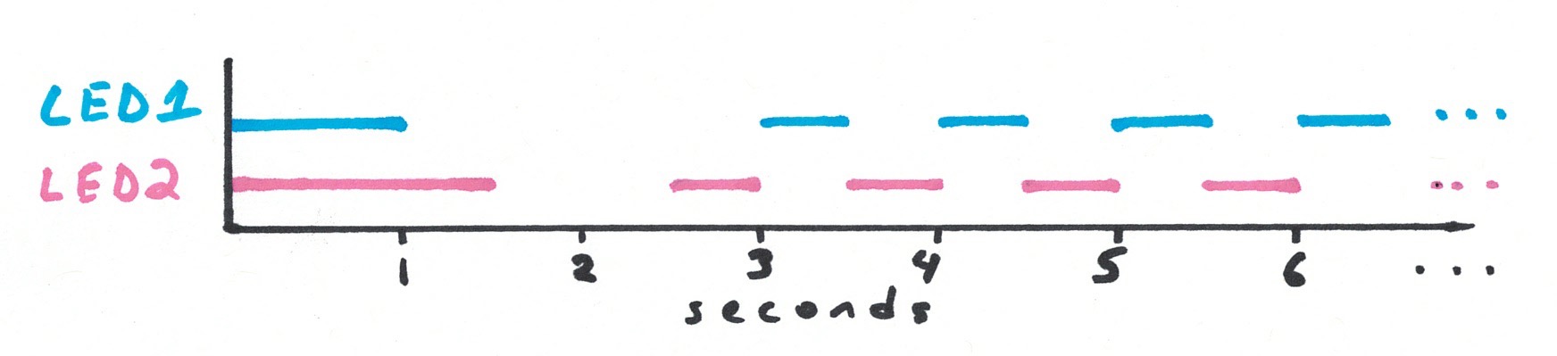
Just in case you’d prefer it in words: LED1 will turn on when the Arduino starts up and be on for one second and turn off. Starting at second 3, it will be on for a half second, then off for a half second, indefinitely. LED2 will turn on when the Arduino starts up and be on for 1.5 seconds then turn off. Starting at second 2.5 it will be on for half a second, then off for half a second, indefinitely.
Your assignment:
-
Build a system making two differently colored LEDs blink in the pattern shown. The colors don’t matter, so long as they’re different. Use your breadboard.
-
Draw a schematic for the circuit(s) you build. Make your drawing on paper, and don’t worry about lines being perfectly straight, etc. You can use the schematic we drew in class as a sort of style guide.
-
Make it so that every time LED1 changes status (i.e. every time it turns on or off), the Arduino sends a serial message back to the computer saying so. The message stream should look like:
        LED1 is on
        LED1 is off
        LED1 is on
        LED1 is off
        ...
We will go around checking everybody’s work at the start of class, so come prepared to run your demo immediately.
I don’t know how to do the third part of the assignment
We’re going to learn a new trick, something we didn’t have time to get to in class, to do part 3 of the homework.
It is possible to tell the Arduino to communicate something back to the computer as it is running. We do this using a feature called “serial communication,” and once you get the hang of it, you’ll find it very useful.
Here’s how you implement serial communication:
1) Tell the Arduino to turn on its serial port. How? With the command Serial.begin(9600);. Since you only need to do this once, the usual practice is to put it somewhere inside of the setup, like so:
void setup(){
    Serial.begin(9600);
}
Of course your setup can contain as many instructions as you’d like; for instance, it could look like:
void setup(){
    pinMode(13, OUTPUT);
    pinMode(10, OUTPUT);
    digitalWrite(13, HIGH);
    Serial.begin(9600);
}
2) Then, as part of the instructions you’re writing, tell the Arduino precisely what text you want it to send to the computer. (If you know about console feedback then this will be familiar.) The command to tell the Arduino to transmit the text hello is: Serial.println("hello");. Therefore, the command to tell the Arduino to transmit the text LED1 is on is simply Serial.println("LED1 is on");. You will need to figure out where to put the serial commands in your code so that the Arduino transmits the right messages at the right time.
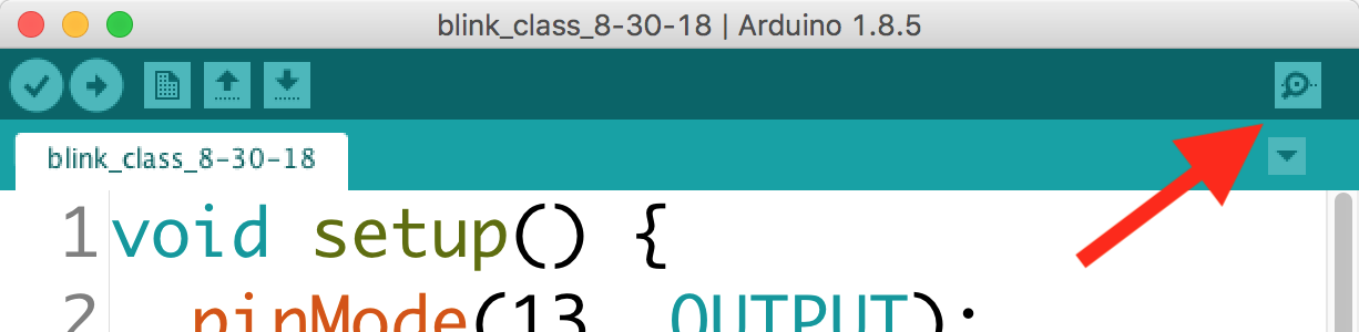
3) To see the serial messages that the Arduino is transmitting to the computer, click on the little magnifying glass in the upper right corner of the Arduino code window:
A window called the “serial monitor” will open up and display your messages. If it’s working properly, it’ll look like this:
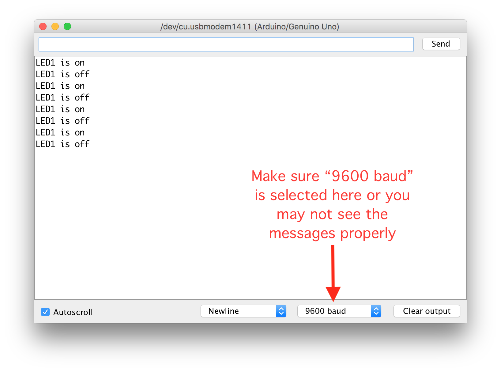
Remember, if you want to restart your Arduino, you can always push the little red “reset” button that’s above the USB connector on the board. Also, you’ll discover that every time you open the serial monitor window it will restart automatically. (Restarting takes less than a second so this is no big deal.)
Collaboration and help
You are welcome to collaborate with your classmates, friends, etc., on this homework assignment. Look up help in any source that you find useful, including the web, reference books, whatever you’d like to use.
However:
-
You must type out the code you use. That means that while you can copy parts of it from another source, you have to type every single letter yourself! We’re building muscle memory. (If you work with a partner, you can both have identical code, but you must both type it out yourself.)
-
You must build your own circuit. You can make the same circuit your friend does, but you have to actually use your own hands to make yours.
-
You must draw your own schematic. It’s fine if it looks the same as your partner’s (I expect nearly every schematic in the class to look quite similar) but you have to draw it yourself.
Questions? Concerns? Email the instructor or TA and ask! We’re here to help.
