LED strip
LED strips are a quick, easy, simple way to get lots of color into a project.
The type we have in the Phys Comp Lab (part # 2001 in our inventory) is composed of a series of small LED modules arranged next to each other on a band of plastic. We buy them on Amazon. Each individual LED module has four connections:
- power (5 Volts in this case),
- ground,
- “data in” (abbreviated
DI), and - “data out” (abbreviated
DO).
The plastic tape has some ebedded wires in it which connect all the LED modules on the strip to power and ground. The data in and data out work a little differently—note the little arrows on the strip:
These show the direction the data flows. The first little module on the left gets data into its left side (DI), and then processes it, and passes the data through, out its DO pin. In this way, the LED strip modules act as a little bucket brigade for the data telling each one which color to light up.
[sold on and uses the
const int BUTTONPIN = 2;

void setup(){
    pinMode(BUTTONPIN, INPUT);
}

void loop(){
    int buttonState;
    buttonState = digitalRead(BUTTONPIN);
    // now buttonState will be either HIGH or LOW, depending on the voltage present at pin 2.
}
The values HIGH and LOW can be used for the purpose of comparison. For instance:
if (buttonState == HIGH) {
    // some code that runs when the button is pressed
}
Switch types
We have a variety of switches available in the Physical Computing Lab, and there is a truly huge range of them out in the world. (For instance, as of this writing, Mouser sells 24,602 types of toggle switches, and Digi-Key sells 25,378 types of pushbuttons.)
Here, we review the switches included in your course kit as well as some other common types.
momentary pushbutton (“tactile” buttons)
This four-legged little button makes a nice “click” sound when you push it. It does not have the internal wiring you may expect. Here’s the button next to a schematic elucidating the wiring:
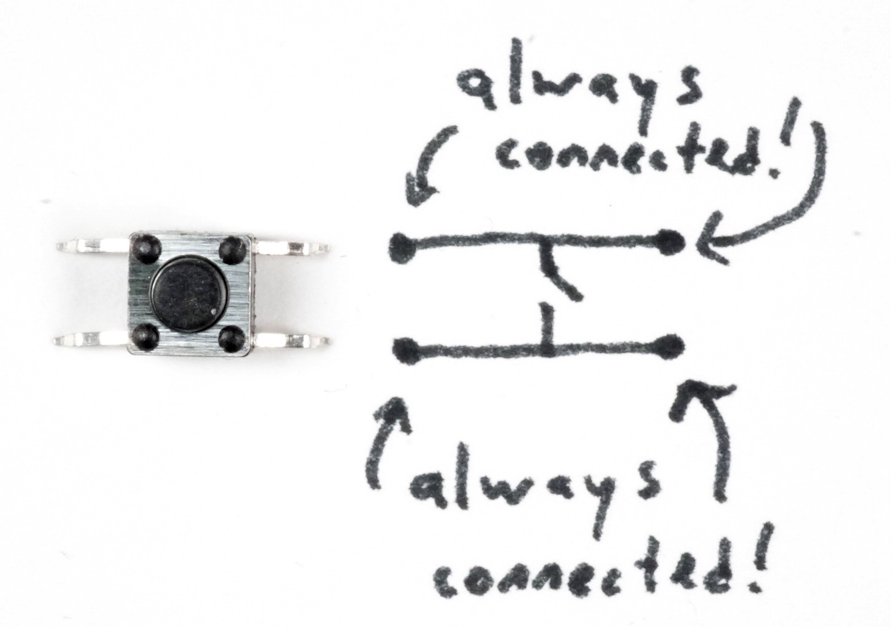
Note that the upper right and upper left legs are always connected to each other, and the lower left and lower right legs are also always connected to each other. The action of the button is to connect the upper part of the switch to the lower part of the switch.
The button is designed with spacing specificically meant to fit across the center dividing valley in a standard breadboard, like so:
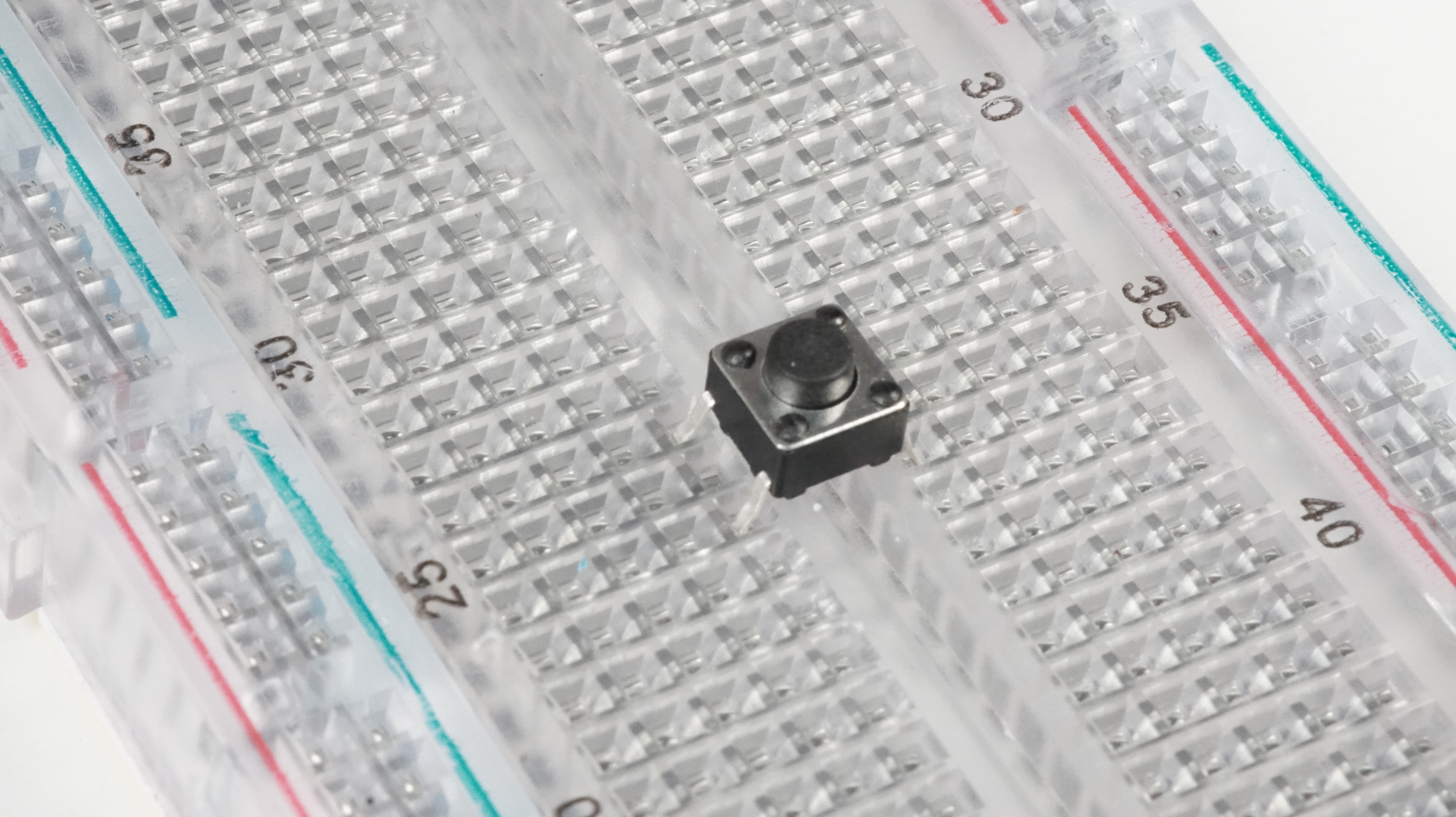
Keep the switch’s surprising internal wiring in mind when using these on a breadboard—the top row of the switch will act as though the electrical row goes across the breadboard’s valley (since the inside of the switch will bridge that gap), and likewise with the bottom.
single-pole double throw switch
This type of simple switch is referred to as “single pole double throw” because there is only one “pole” that the switch operates (the center pin in this case), and that single pole has two possible connections (“throws”) it can make. It is a “maintained” switch, as opposed to “momentary,” meaning that it will remain in the last position it was pushed into (it has no internal spring unlike a momentary switch).
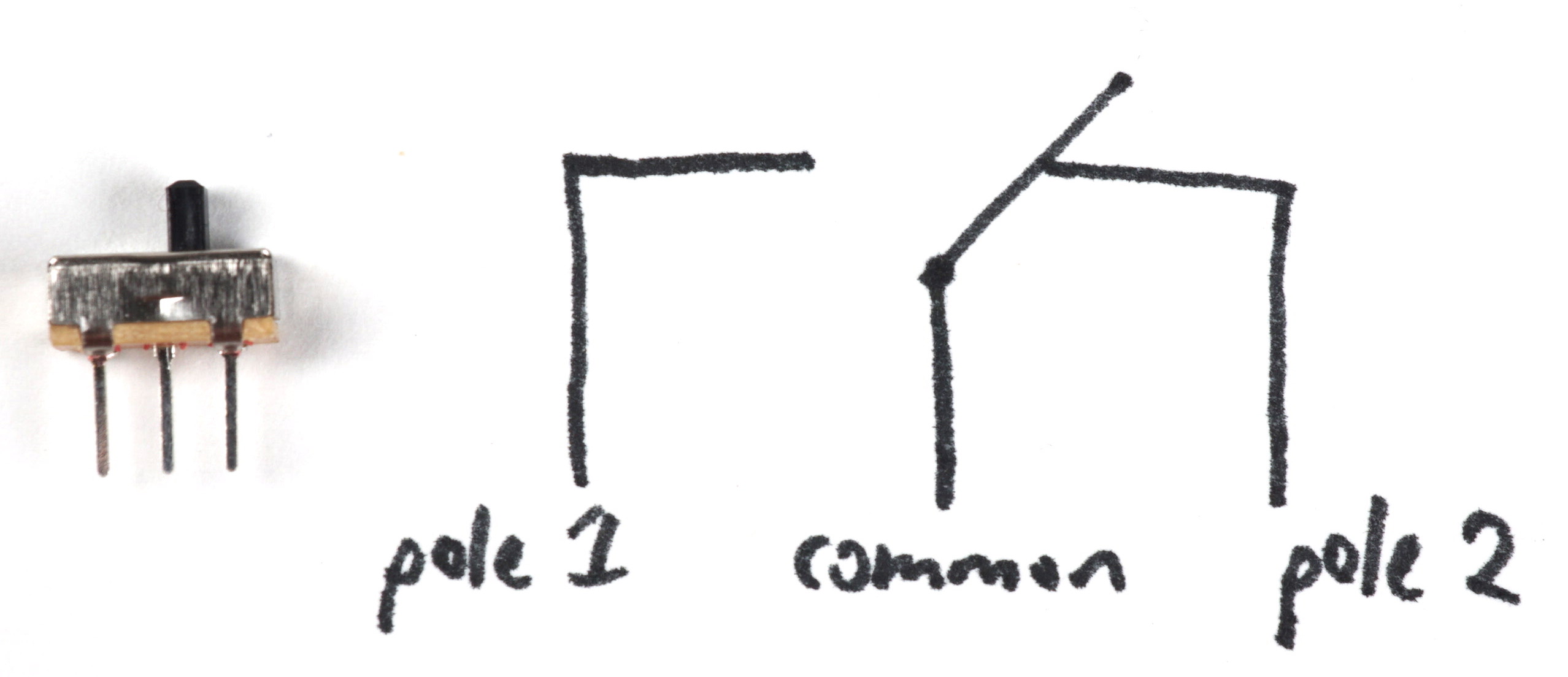
The center pin will either always connect to the left pin, or to the right pin. The left and right pin will never connect to each other, unless there’s a mechanical fault inside the switch. (Which is possible!)
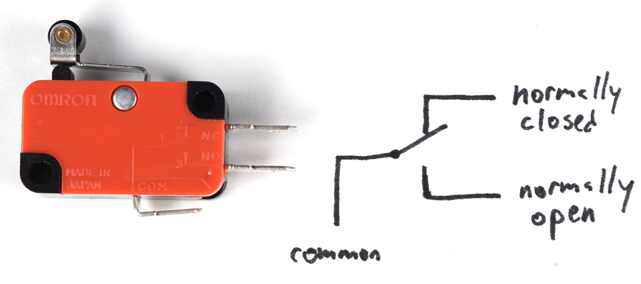
micro limit switch, or micro lever switch
These small switches can be used as “limit” switches, meaning they detect when something moving in a straight line is brought into physical contact with something else in a fixed position. This position would be defined as the “travel limit” of a physical part, and it is a common operation in electronically controlled motion systems to move something along an axis until it contacts a limit switch at the end.
The switches are called “lever switches” because of the way they’re built—that arm sticking out of the switch is a small lever, and the switches come in a variety of lever length shapes and sizes to accommodate different design needs.
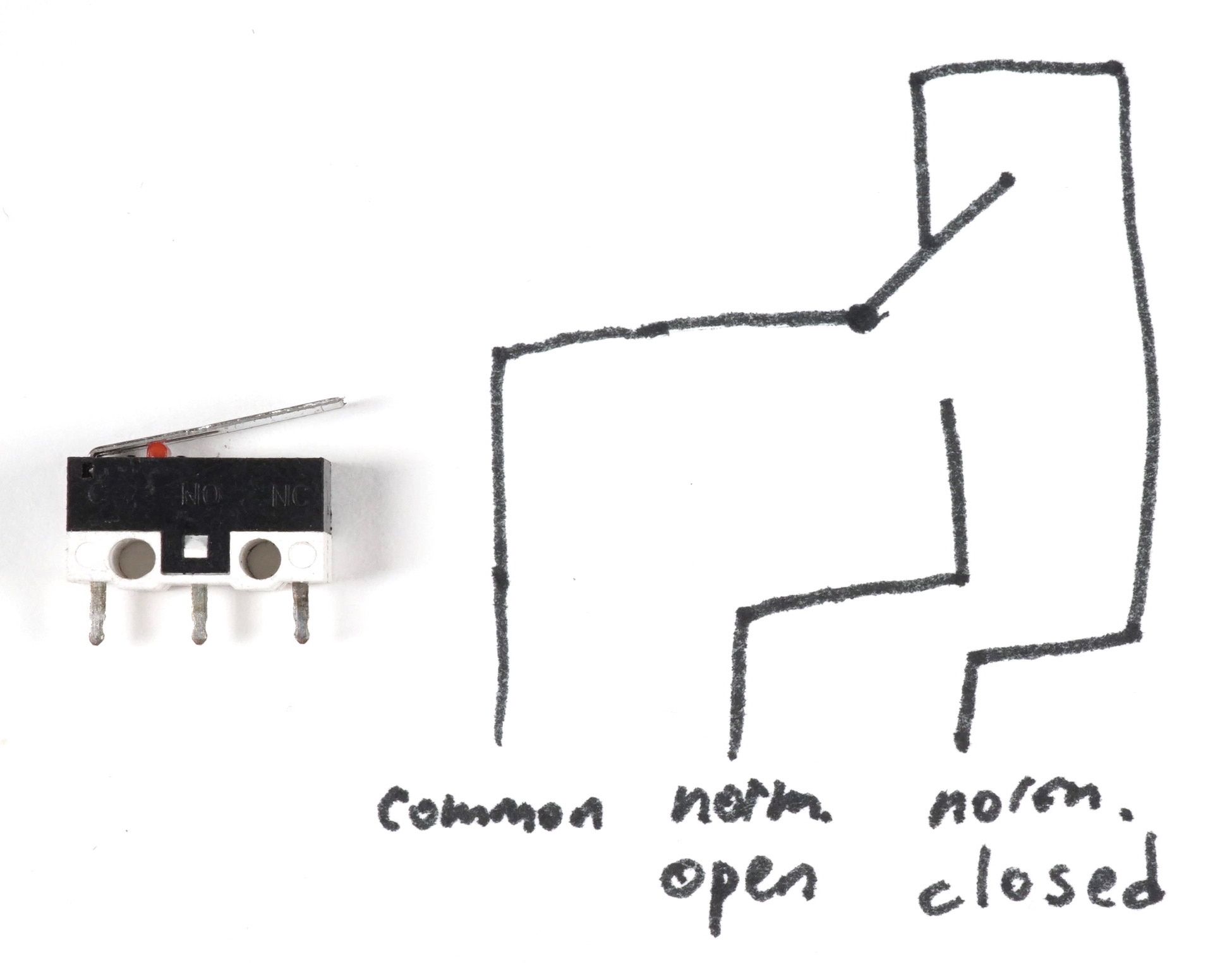
If you look very closely, you can see the switch’s markings in raised letters on the plastic body; the legs are marked from left to right, C, NO, and NC, which mean “common,” “normally open,” and “normally closed” respectively. (“Normal” refers to when the button/lever is not being pushed.)
mini lever switch
This switch is the slightly-bigger cousin of the micro lever switch. It is more robust mechanically, and designed to fit into standardized tabbed holders in various kinds of machinery. It has a roller at the end of its arm, which means that it could be used, for instance, as a cam follower, or some other application where the motion of the thing contacting the switch wouldn’t necessarily always be perpendicular to it.
Note that in the case of this switch, there was enough space on the plastic housing that the manufacturer was able to draw a small, albeit legible schematic of the switch.
footnotes:
