Context
Richard is a graphic and jewelry designer who typically works on drawings for commissions every evening on the couch while he and his wife watch the news. You can see the notes from our initial meeting here.
While he does this, he often has to tilt and position his iPad in different ways to get the right angle to draw from. He typically keeps it on a pillow and props it up with his hand, which doesn’t allow for it to be fully stable, and makes drawing harder. He tries to keep track of the time he’s spent working on each commission in order to keep pricing fair and know for future reference how long similar designs take.
We worked to create a prototype for him to review and give us feedback.
Prototype
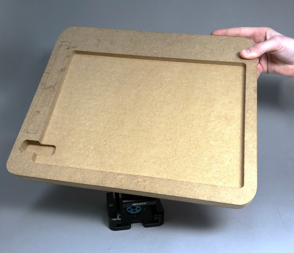
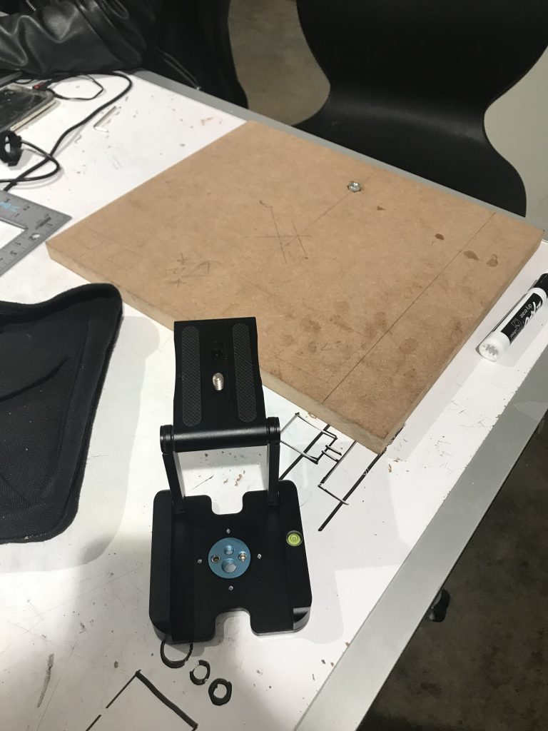
Our prototype gave Richard a sense of the scale of the final product, so as to demonstrate both the movement of the board and to understand and look critically at the experience of using the device to assist you in drawing on an iPad. The stand attaches to the back of the board and sits on a table, where it can be moved up and down to better suit Richard’s desired angle of drawing.

The front of the board holding the iPad was milled to hold Richard’s 12 inch iPad
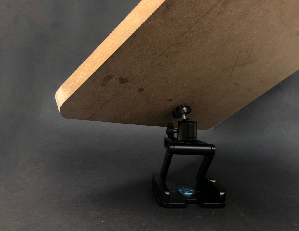
Back view showing the positioning joint attached to the back of the holding board.
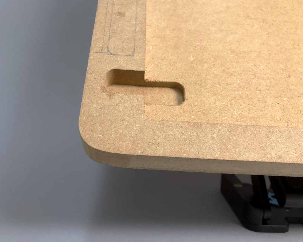
Finger slot to allow Richard to get his iPad back out of its holder.
Process Photos
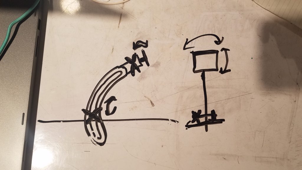
Our initial sketch for the arm mechanism featuring a sliding slot joint for vertical movement and a ball & socket joint for planar rotation.
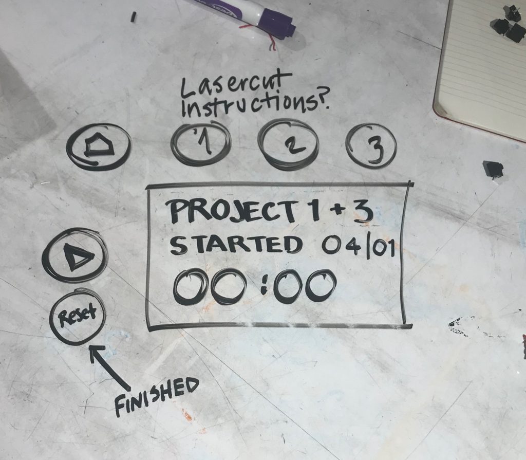
Our initial sketches for the digital interface on the board featuring different buttons for each project, a home button, and start and finish buttons, intended to be built with the LED screens in the Physical Computing room.
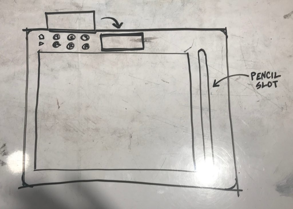
Initial sketch of how all the components would look on the board.
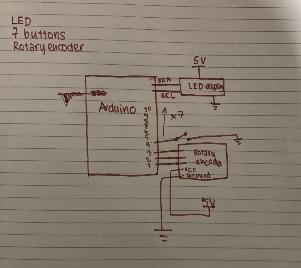
An initial circuit diagram.
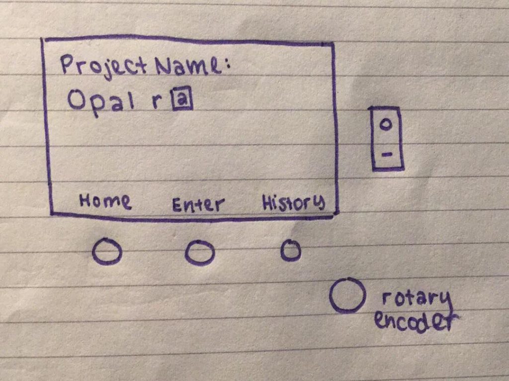
Final concept for electronics interface, coded but with nothing to show as we do not have the display yet, designed around usage of a TFT LED display, which sets a display through individually coded pixels, allowing us to change font sizes and placements to add on-screen variable labels to buttons, cutting down to only three. A rotary encoder allows Richard to enter the name for each project, and an additional power button allows the entire arduino to turn off when not in use, saving battery power.
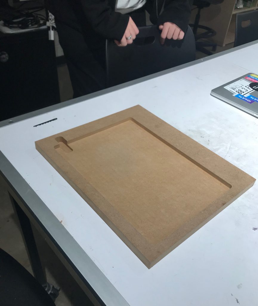
Prototype board with space for iPad milled in along with a finger slot to get it out again.
We initially tried to attach the camera mount to the board by inserting a hex nut into the board for the camera mount to screw into.
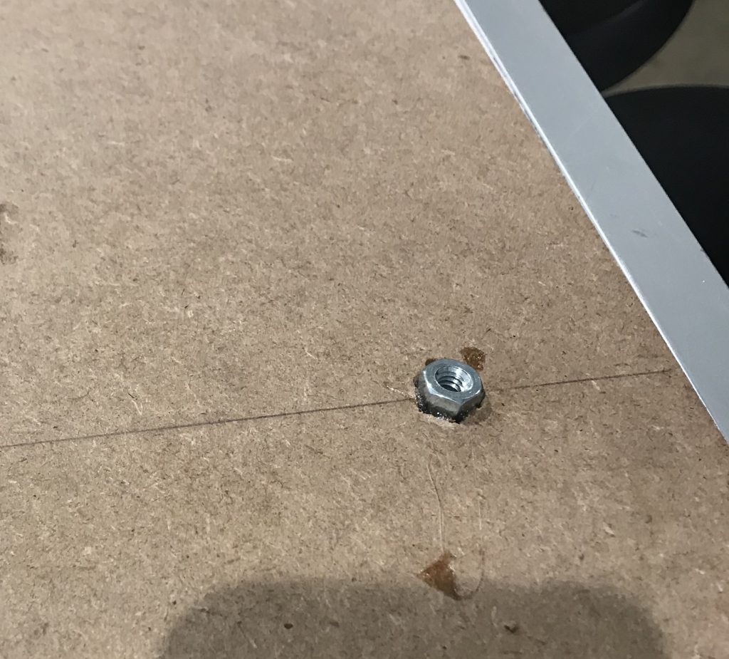
Closer shot of initial attempt to mount board to the camera equipment w were using as a joint. WE tried to embed and glue a nut into the MDF.
Discussion:
Many of the challenges we faced during this process involved getting the right parts to mount the board on. We knew that finding a combination of parts that allowed easy movement using a joint that wouldn’t collapse under the weight of the board, while positioning the board in a way that it wouldn’t tip over or rest too high above whatever surface it was placed on would be difficult, so we tried to focus on the mechanical aspect of this prototype. It took us a long time to find the right parts to order for the joint, which delayed our finding a good way to attach the joint to the board properly, and multiple different iterations of how Richard would interact with the LCD interface delayed us in getting a functional electronic prototype.
In order to be able to use the LED displays already available in the physical computing room, which display text in clusters of pixels and can only allow text inputs in a constant size, we created a system with 7 buttons, allowing us to have a constantly defined button for each conceivable purpose, including three buttons labelled as three different projects. Initially, we envisioned the working projects as simply being numbered as project 1, 2, and 3, but then decided that, as a record of previous projects would be an important part of the purpose of tracking the time for each project, when a project was completed, the next project should be labelled #4 and so on. Because the buttons for project 1, 2, and 3 were to be labelled with those numbers and placed in order, we reasoned that this would be confusing when, for example, project 2 was completed and the list became 1, 4, and 3. Additionally, past the first few projects, the numbers corresponding to different past projects would no longer be reasonable to remember, so we decided to add a method of naming each project. We looked for Arduino compatible keyboards, but decided that that would be an unnecessarily large component that would not fit into our already designed dimensions of the physical board. Instead, we added a rotary encoder, programmed to enter text letter by letter. We also decided to purchase a TFT display, and created code that would allow each button to be labelled on the display, allowing us to cut down to 3 buttons.
While during the presentation we didn’t have much time to get questions from the audience, we got helpful feedback from Richard regarding ways to make the form easier for him to use, such as adding a finger slot to the side of where we milled a place for his Apple Pencil to rest, and rounding out the right edge of the board so that his forearm wouldn’t chafe when he was drawing. He experimented with angles at which he would usually hold the iPad, and found that the fit was secure, but asked if we could add elastic on corners or hollow out the space below the top edge for a snugger fit on top when the iPad is at a high angle. We also were able to ask him more specific questions about his habits around taking commissions that we weren’t able to ask during our initial meeting because we hadn’t fully settled on an idea to probe more into the behavior around it; for example, he told us that he works on around 5 at a time, and would like to have them labelled in the system, supporting our choice to shift from constant buttons assigned to three projects at once to a menu system.
It would have been helpful for us to have at least some of the circuitry and software finished so that we could see if he felt comfortable interacting with it, and able to understand the basic mechanisms and instructions to use it. While we showed him paper sketches of what the interface and surrounding hardware would most likely look like and how it would be used, and he showed no issues in understanding how it would work, it would have been helpful to have had some part ready for him to interact with. Often hearing how something will work is easy to understand, actually using said thing is often when problems arise.
Our next steps include deciding on a final form factor for the board and creating the electronic interface. The arm mechanism has been finalized at this point, so we need to either find or design a bracket to interface with the holder. Next, the electronic aspects and layout need to be finalized in order to decide a final form factor for the holder. Code has been written and compiled but not physically tested, due to not having built the circuitry that would allow it to operate, which we will be able to do once we receive the new display. Once the electronics are taken care of, the test board will be milled and the prototype assembled to verify that the form factor is satisfactory. We plan to meet with Richard before the final critique to make sure that he is happy with our functional prototype before we move to our final version. After this meeting, the final board and baseboard will be made and polished and the final product assembled.
Comments are closed.