Reading Assignment: Make It So, 3/17

Reading assignment: Chapters 6 and 10 Of Make it So

Chapter 6: Sonic Interfaces

The authors establish 2 major categories for sonic interfaces: sonic output and voice interfaces. The chapter covers outputs including considerations for effects such as alarms, ambient sound such as buzzing or clattering made by machinery, and directional sound. Topics around interfaces deal with music and multiple types of voice interfaces, including more sophisticated conversational interfaces. I agree that the more sophisticated the voice interface, the more that is expected out of it (for example, when dealing with the automated voice when calling insurance or the bank).  Still, I’m surprised that there still is not a feature that allows automated systems to measure how annoyed a person is getting with the system (for example, syllables becoming more terse, or volume increasing) and getting the caller over to a human associate as quickly as possible. Perhaps everyone gets terse and annoyed, so there’s no need to measure it, or rank people by the amount that the automated system annoys them.

—-

Chapter 10: Communication

I was interested to see authors using terms “asynchronous” and “synchronous,” which I’m sure have been used in discussions around communication for a long time, but I only started seeing that term at the start of COVID-19 to make a distinction between a zoom call and a zoom recording. The chapter identifies the functions needed in both categories of communication: composing, playback, activation, connecting between caller and receiver, connection monitoring, ending a call. Other considerations addressed include volume control, accompanying visuals/video, mute functions, language translation, and disguises. One of the noted opportunities- subtle appearance alteration (lighting correction, blurred background, etc)- is realized today with features on Zoom.

One of the subjects addresses is the complexities of language translation- it reminded me of an article I read about the challenges of translating Twenty Fragments of a Ravenous Youth, written in Chinese by  Xiaolu Guo. The author describes the language of the book as “slangy, raw Chinese” and the article discussed the difficulties of conveying that tone and the cultural connotations associated with it into English. By comparison, machines attempting to translate in real time would be at an even greater disadvantage. Perhaps the translate-in-real-time would be forced to restrict itself to austere and utilitarian function, or risk completely missing the boat.


Class Notes, 15 Mar 2022

Class 15: 15 Mar

Why is sound important?  How do you close your “ear-lids” when you go to sleep?  Is sound our first evolved sense that is effectively an interrupt for an external event not touching our skin?

If you’re interested in a deep dive in to sound design:”Designing with Sound: Fundamentals for Products and Services” starts out with a vocab for sound design: https://amzn.to/3JiAikD

We’ve been thinking about sound as philosophy for quite awhile, how do we learn to make sounds as children?  https://www.youtube.com/watch?v=8fHi36dvTdE&feature=youtu.be&t=920

We learn to make some sounds as children but can never learn them as an adult learning another language.  The Russian vowel Bbl is one example

You can learn to have “perfect pitch” if you start as a child: https://www.youtube.com/watch?v=816VLQNdPMM

Close your eyes after following links in this section.  don’t worry about the visual details and information, this is learning to understand sound and signals

Some of these examples are long, 10-20min.  I’m only including ones worth listening to from start to finish.

classes of sounds (one view)

Signals and alerts – short sounds that transfer information

INSERT photo of our doorbell

Information over time – songs and patterns

– information, many of them skeuomorphic

– air raid siren, dual pitch:

( my borough uses this as the 15 minute warning on curfew for minors!)

– tornado sirens:  https://www.youtube.com/watch?v=Djqi86jMl5g

– Victorian houses used remote bells to alert servants and family, bell pull at the front door to let people know someone has arrived

DIY air raid siren, there are a lot of these on Thingiverse (equiv)  https://www.youtube.com/watch?v=ZVDmbFXFTj0

Music and entertainment

  • ringing phones are so unique that we map and learn our own ringtones using songs.  Golan Levin’s mobile phone concert was only possible because phones had ring tones that couldn’t be changed.
  • Star Trek had one of the earliest catalogs of special effects sounds used to alert viewers of plot elements and activity.
  • Professional companies that sell sound libraries. sizzling fajitas podcast
  • Chili’s used the sound of sizzling fajitas to sell them, not their flavor:
    https://99percentinvisible.org/episode/the-sizzle/

We like things that reflect heartbeat rhythm, this goes back to dance for thousands of years, continue to do this in today’s music with multiple tempo compositions

Orbital and Underworld are two electronic bands using dual internal tempos, one near the rate of resting heart beat the other near the rate of active (dancing) heart beat.

mini-assignments:

Reading: Make it So Chapters 6, 10

Make your Teensy make some noise

Ambient Sounds: Washing Machines and Credit Card Machines

Growing up, the washing machines I knew would indicated that clothes were ready to put into the dryer either by 1) silence, or 2) a long, flat buzzing noise. Newer washing machine models have a new approach (so distinct I remember my mother commenting on her new one from several years ago)- now, they sing. The latest one in my current unit has lets loose a rousing, merry tune for about 30 seconds before falling quiet. It’s catchy, and it feels more like a cheerful reminder than an angry “get-over-here-and-finish-your-chores-now” admonishment.

Another (relatively) recent tone change is the sound of the card machine at cashier registers. Older card machines would make more unpleasant noises (buzzes, beeps) that carried a vaguely disapproving connotation, while newer ones make a cheerier sound. It makes sense that a vendor would want the card machine to make a gratifying noise, since it rewards the customer. It wasn’t something I ever thought of before the happier noise was more prevalent. After that, it seemed a no-brainer that when completing a credit card transaction, happy noises should be coming from the machine that takes my money. Although I realize it is all my human auditory perception, the older, angrier-sounding machines begin to feel undeserving.

Crit 1: Motion – The Plant Rotater

The automatic plant rotater helps indoor plant owners ensure that their plant gets even exposure to sunlight, even when the source of sunlight is one directional. This reduces the amount that a plant will grow to one side, which can result in an undesirable aesthetic, and in extreme cases, a plant that needs additional weights and staking to stay up. A common solution is for the caretaker to rotate the pot regularly, but this can be a difficult task to keep track of. See the picture below for extreme case of succulents trying to seek out the light (and an owner irregularly rotating the pot for correction)!

The hormone auxin is commonly responsible for triggering a plant to grow towards the light. Unless a plant is irregularly shaded in its environment, this hormonal response usually encourages plant to grow upward. 

A light sensor is placed near the plant, on the side exposed to the most amount of light. It measures the light exposure at regular intervals, and when it has detected the “preferred total exposure” it will rotate the plant by a quarter turn. Since sunlight will vary throughout the day, the plant rotates based on exposure instead of based on a timer. If desired, the owner can press a button to rotate the plant before the “preferred total exposure” is reached, which allows for greater control.

When connected to p5js, each time the plant turns, information about the latest total light sum (light exposure since the last turn), the preferred total exposure, and the total number of turns is sent through the Serial Port to p5js. The P5js sketch below does several tasks:

  1. Lists the array of numbers sent from the Arduino
  2. Calculates “percent complete” which is a percentage of Total Light Exposure Since Last Turn/Preferred Total Exposure. For turns triggered by the sensor, we would expect this number to be about 100% while it could be anything lowered when the turn is triggered by a button press.  If the plant is exposed to a significant amount of light at once, the number could be over 100%.
  3. Illustrates the Total Light Exposure adjacent to the Preferred Total Exposure to provide a user with a visual.
  4. If the Percent Complete value falls within a defined range (ex: 60-125%), there will be a smiley face on the screen. If the value falls outside of this range, a frowny face will appear instead. The visualization provides a quick reference for the user to understand what is going on without having to interpret the numbers flashing on the screen.

Arduino Sketch:

//motor and light sensor

#define lightPin A0 //Ambient light sensor reading 
#include <Stepper.h>

//data smoothing and light sensor
const int numReadings = 100;
float ligReadings [numReadings];
int ligReadIndex = 0;
float ligTotal = 0;
int inputPin = lightPin; //put sensor pin here
float ligPer=0;
float light_percent=0;
int prefLigExp=150;

//stepper motor
int stepsPerRevolution = 2048; //see motor spec sheet
int motSpeed = 10;
int dt = 500;
Stepper stepmot(stepsPerRevolution, 8, 10, 9, 11); //see motor and driver specs

//for millis
unsigned long lastReadTime = 0;

//for button
const int buttonPin = 2;
int buttonValue = 0;

//p5jsturncount
int numberOfTurns = 0;

void setup() {
  pinMode(lightPin, INPUT);
  pinMode(buttonPin, INPUT_PULLUP);

  for (int thisReading = 0; thisReading < numReadings; thisReading++) {
    ligReadings[thisReading] = 0;
  }

  Serial.begin(9600);
  lastReadTime = millis();
  stepmot.setSpeed(motSpeed);

}


void loop() {
  //millis and light sensor
  if ((millis() - lastReadTime) >= 5000UL) {
    //Serial.println(lastReadTime);
    //Serial.println(millis());
    lastReadTime = millis();
    //light sensor read
    float light = analogRead(lightPin);
    float light_ratio = light / 1023.0;
    float light_percent = light_ratio * 100;

    ligTotal = ligTotal - ligReadings[ligReadIndex];
    ligReadings[ligReadIndex] = light_percent;
    ligTotal = ligTotal + ligReadings [ligReadIndex];
    ligReadIndex = ligReadIndex + 1;


  }

  buttonValue = digitalRead(buttonPin);


  if (buttonValue == LOW) {
    stepmot.step(stepsPerRevolution / 4);
    numberOfTurns=numberOfTurns+1;
    Serial.print(ligTotal);
    Serial.print(",");
    Serial.print(prefLigExp);
    Serial.print(",");
    Serial.println(numberOfTurns);
    ligTotal = 0;
  }


  if (ligTotal >= prefLigExp) {
    stepmot.step(stepsPerRevolution / 4);
    numberOfTurns=numberOfTurns+1;
    delay(3000);
    Serial.print(ligTotal);
    Serial.print(",");
    Serial.print(prefLigExp);
    Serial.print(",");
    Serial.println(numberOfTurns);
    //make step stop rotating
    ligTotal = 0;
    //ligReadIndex=0;
  }

  else {
    stepmot.step(0);
  }


}


p5js Sketch:

//smiley sketch: https://medium.com/spidernitt/introduction-to-digital-art-with-p5-js-d8ba63080b77
//serial, sensors, arrays, and p5js: https://www.youtube.com/watch?v=feL_-clJQMs

let serial; 
let sensors = [256,256,0];
let newData = "waiting for data";
let px, py;
let rad1;
let rad2;
let rad3;
let potDiameter;

function setup() {
  createCanvas(windowWidth, windowHeight);
  stroke(255);
  let radius = min(width,height)/2;
  let rad1=radius*0.7;
  let rad2= radius*.5;
  let rad3= radius*.25
  px= width/2;
  py = height/2;
  potDiameter = radius*1.5
  serial = new p5.SerialPort();
  serial.list();
  serial.open('COM5');
  serial.on('connected', serverConnected);
  serial.on('list',gotList);
  serial.on('data',gotData);
  serial.on('error',gotError);
  serial.on('open',gotOpen);
  
}

function serverConnected() {
  print("Connected to Server");
}

function gotList(thelist) {
  print("List of Serial Ports:");
  
  for (let i=0; i < thelist.length; i++) {
    print(i + " " + thelist[i]);
    
  }
}

function gotOpen() {
  print("Serial Port is Open");
}

function gotClose() {
  print("Serial Port is Closed");
  newData = "Serial Port is Closed";
}

function gotError(theerror) {
  print(theerror);
}

function gotData() {
  let currentString = serial.readLine();
  trim(currentString);
  if (!currentString) return;
  sensors=split(currentString, ',');
  console.log(sensors);
  newData = currentString;
}


function draw() {
  background(255,255,255);
  fill(50,25,0);
  strokeWeight();
  text(newData,10,10);
  
  //numTurns=newData
  //text(numTurns,px,py)
  
  totExp=sensors[0];
  prefExp=sensors[1];
  numTurns=sensors[2];
  //strokeWeight(.5);
  text("Turn:"+ numTurns,px,py+75);
  perc = (totExp)/(prefExp)*100;
  text("Percent Complete:"+ perc,px,py+90);

  text("Preferred",px+60,py+20);
  noStroke();
  fill(200, 150, 0);
  rect(px+55,py, 55,-sensors[1]);
  
  strokeWeight(1);
  fill(50,25,0);
  text("Received",px,py+20);
  
  noStroke();
  fill(200, 200, 0);
  rect(px,py,55,-sensors[0]);
  
  if (perc >=60 || perc <=125) {
    smiley(px, py-10, 30);
  }
  if (perc <60 || perc >125) {
    frowny(px,py-10,30);
  }
  
  
function smiley(x, y, diameter) {
  // Face
  fill(255, 255, 0);                  //fills the face with yellow color
  stroke(0);                          //outline in black color 
  strokeWeight(2);                    //outline weight set to 2
  ellipse(x, y, diameter, diameter);  //creates the outer circle

  // Smile
  var startAngle = 0.1 * PI;          //start angle of the arc
  var endAngle = 0.9 * PI;            //end angle
  var smilediameter = 0.5 * diameter;  
  arc(x, y, smilediameter, smilediameter, startAngle, endAngle);

  // Eyes
  var offset = 0.15 * diameter;
  var eyediameter = 0.05 * diameter;
  fill(0);
  ellipse(x - offset, y - offset, eyediameter, eyediameter);
  ellipse(x + offset, y - offset, eyediameter, eyediameter);
}

  function frowny(x, y, diameter) {
  // Face
  fill(255, 150, 0);                  //fills the face with yellow color
  stroke(0);                          //outline in black color 
  strokeWeight(2);                    //outline weight set to 2
  ellipse(x, y, diameter, diameter);  //creates the outer circle

  var startAngle = 1.2 * PI;          //start angle of the arc
  var endAngle = -0.2 * PI;            //end angle
  var smilediameter = 0.5 * diameter;  
  arc(x, y+8, smilediameter, smilediameter, startAngle, endAngle);

  // Eyes
  var offset = 0.15 * diameter;
  var eyediameter = 0.05 * diameter;
  fill(0);
  ellipse(x - offset, y - offset, eyediameter, eyediameter);
  ellipse(x + offset, y - offset, eyediameter, eyediameter);
}


}


Crit 1 (Using the outdoors for heating/cooling) – Jud

Idea:

The main idea behind this project is to open the window to cool or heat your room when the outside temperature is what you want your room temperature to be. For example, in the summer, if it is a super nice day out and your room is very hot, you could enter a temperature into the system and it would automatically open the window to let outside air in to adjust the room temperature. This also has a dual purpose in the winter for if your house is too hot and the system could open the window to let a cool breeze in.

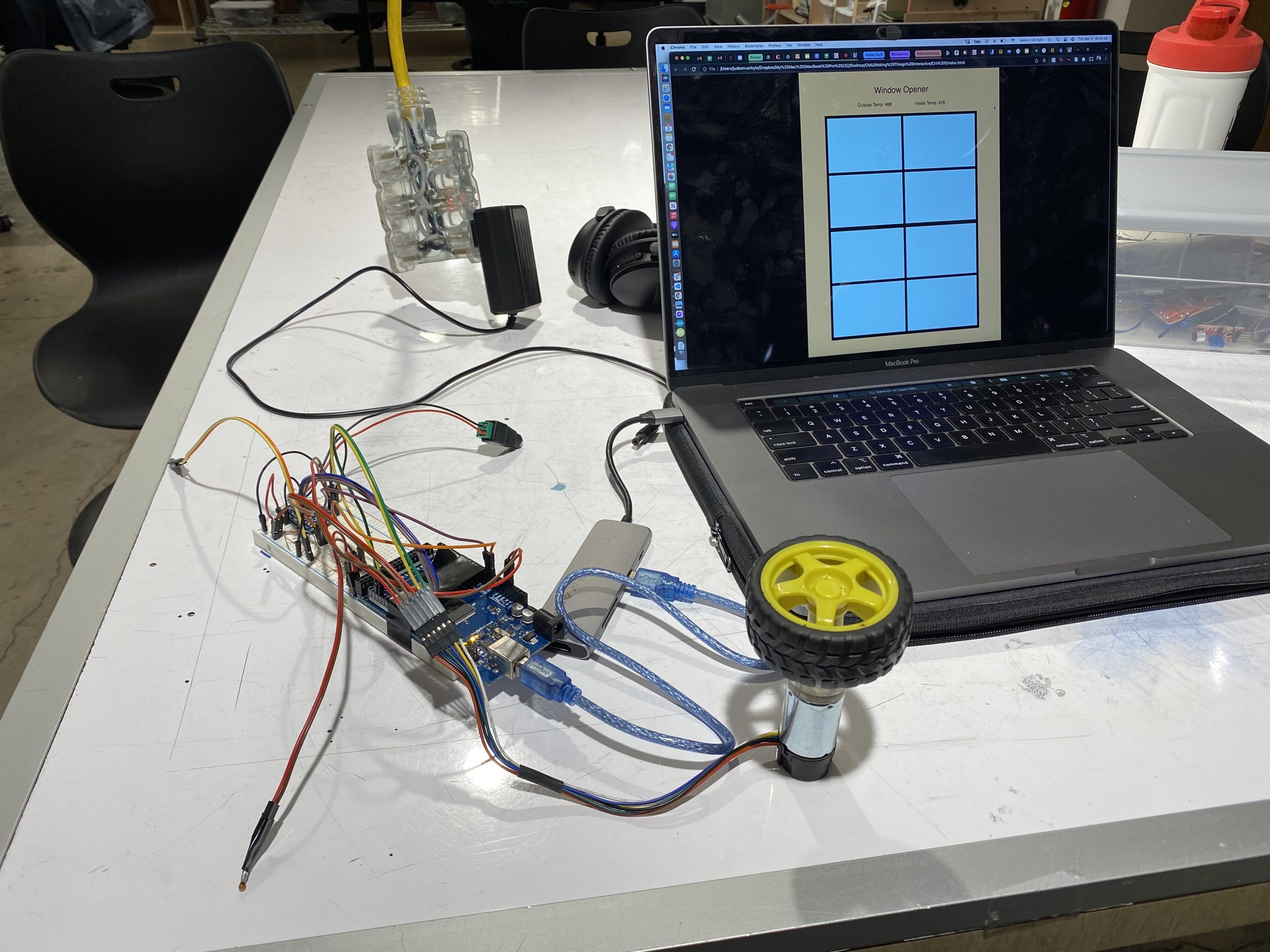
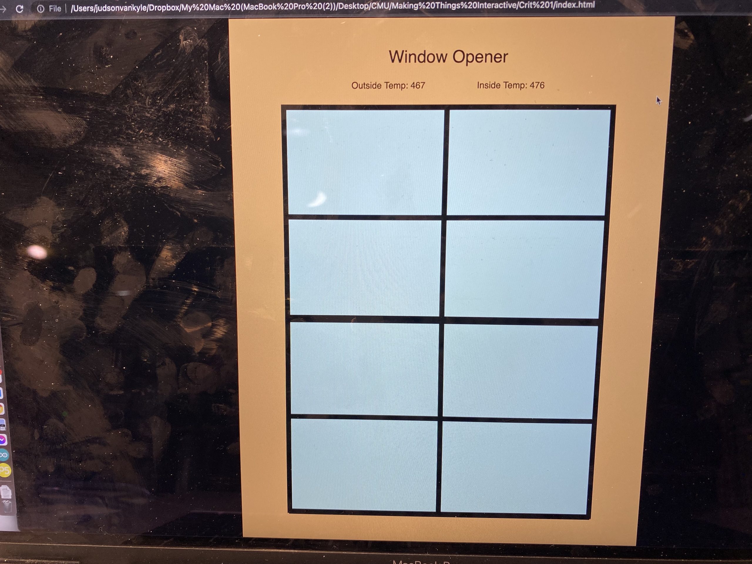
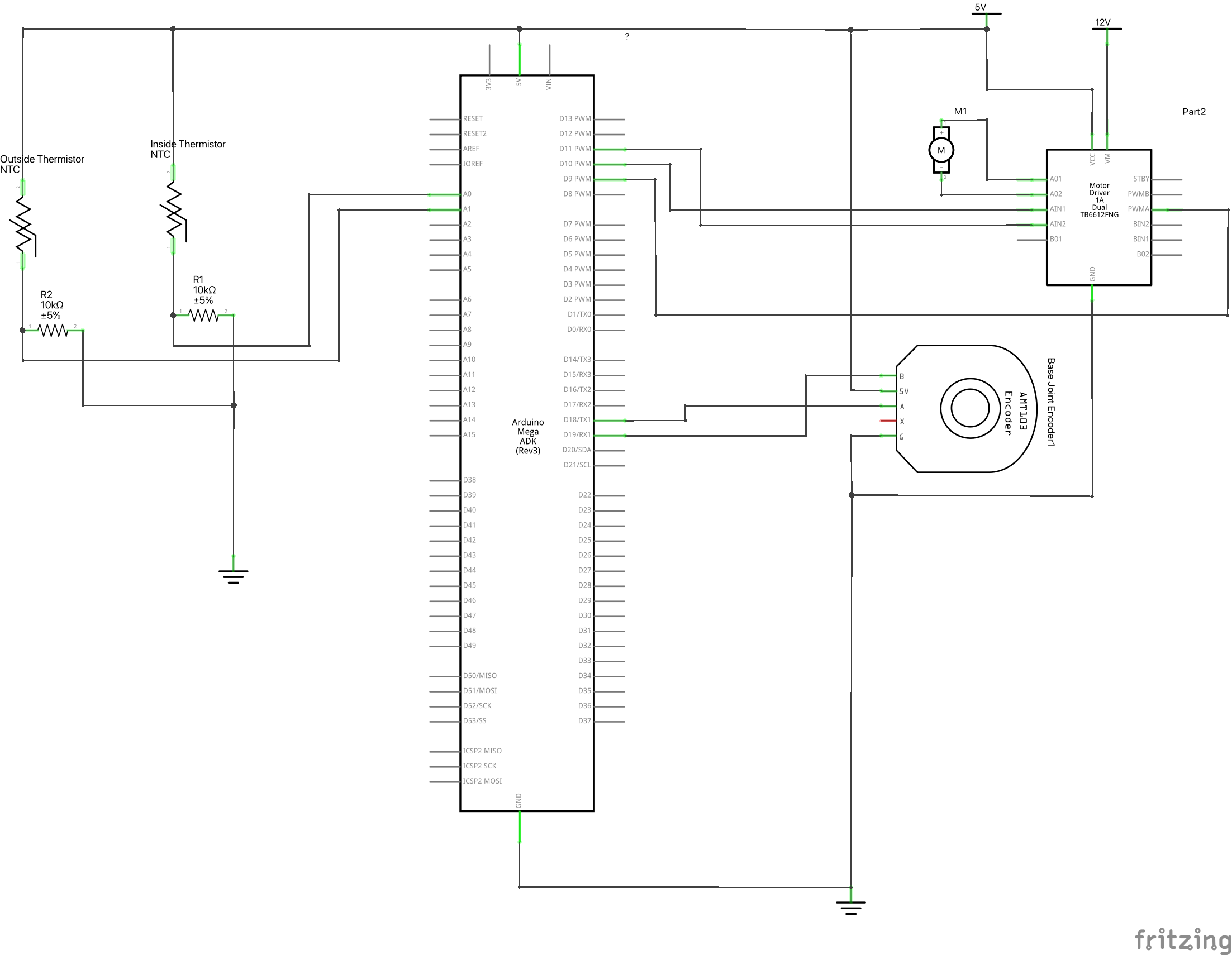
The main components of this system are two thermistors for measuring outside and inside temperature, a motor with an encoder to actuate the window, a motor driver to control the speed of the motor, and a p5 script animating the information from the Arduino in a helpful way. The Arduino sends the data over serial communication to the p5 script which then displays this information to the user and animates the virtual window corresponding to the current motor position.

As shown in the demo video below, the system works very well detecting a need for opening the window and acting upon it. In addition, the p5 script very accurately shows the degree of openness of the window. While these component work very well together, the controller is still fairly simple. Currently, there is just one setting for open and closed meaning the window doesn’t open a certain degree based off the temperature difference between the room and the goal temp. With more time this feature could be implemented, but for demonstration purposes of this concept, the current controller works well.

Images:

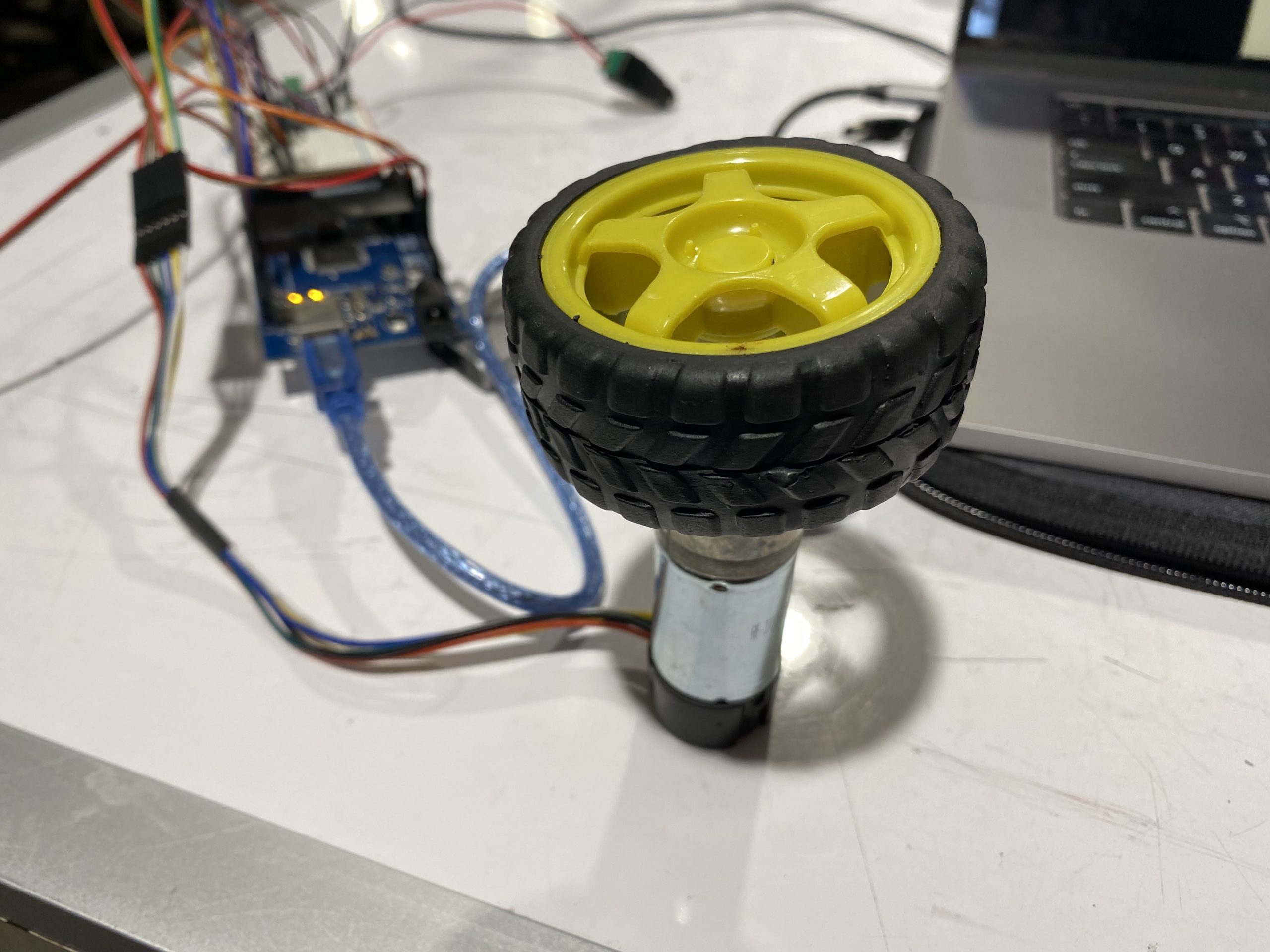
Here are images of the final system concept. The first image is an overall image showing both the physical build and the virtual animation. The second image is a close up of the virtual animation screen showing the displayed outside and inside temperatures as well as the window itself. Finally, the third image shows a top view of the physical wiring for the system.

Videos:

Video demonstration of the motor position feedback controlling the amount the virtual window is open.

Here is a video of the full system demo. As shown, when the outside temperature rises above the inside temperature, the window opens. When the outside temperature falls below the inside temperature, the window closes.

Code:

P5.js

let serial;
let latestData = "waiting for data";
var outData;

var minWidth = 600;   //set min width and height for canvas
var minHeight = 400;
var width, height;    // actual width and height for the sketch
var squareWidth = 100;

var OuterWindowHeight = 800;
var OuterWindowLength = 600;

var InnerWindowHeight = OuterWindowHeight/2;
var InnerWindowLength = OuterWindowLength;

var panelThickness = 10;
var RoomLength = 800;

var bottomInnerWindowY;
var y = 0;

var roomColor = '#f7c07c';
var skyColor = '#c2f9ff';

var outsideTemp = 100;
var insideTemp = 100;

var prevString;


function setup() {
 // set the canvas to match the window size
 if (window.innerWidth > minWidth){
  width = window.innerWidth;
  } else {
    width = minWidth;
  }
  if (window.innerHeight > minHeight) {
    height = window.innerHeight;
  } else {
    height = minHeight;
  }

  bottomInnerWindowY = (height - OuterWindowHeight)/2 + 50 + OuterWindowHeight - InnerWindowHeight/2;

  //set up canvas
  createCanvas(width, height);
  noStroke();

 serial = new p5.SerialPort();

 serial.list();
 serial.open('/dev/tty.usbmodem144101');

 serial.on('connected', serverConnected);

 serial.on('list', gotList);

 serial.on('data', gotData);

 serial.on('error', gotError);

 serial.on('open', gotOpen);

 serial.on('close', gotClose);
}

function serverConnected() {
 print("Connected to Server");
}

function gotList(thelist) {
 print("List of Serial Ports:");

 for (let i = 0; i < thelist.length; i++) {
  print(i + " " + thelist[i]);
 }
}

function gotOpen() {
 print("Serial Port is Open");
}

function gotClose(){
 print("Serial Port is Closed");
 latestData = "Serial Port is Closed";
}

function gotError(theerror) {
 print(theerror);
}

function gotData() {
  let currentString = serial.readLine();
  trim(currentString);
  if (!currentString) return;
  console.log(currentString);
  // latestData = currentString;
  // currentString = Number(currentString) - 10000;
  if ((Number(currentString) - 10000) < 10000) {
    insideTemp = (Number(currentString) - 10000);
    return;
  }
  else if ((Number(currentString) - 20000) < 10000) {
    outsideTemp = (Number(currentString) - 20000);
    return;
  }
  else if ((Number(currentString) - 30000) < 10000) {
    y = (Number(currentString) - 30000)/1000;
    return;
  }
}

function draw() {

  var outerWindowBottomY = (height - OuterWindowHeight)/2 + 50;
  var topInnerWindowY = outerWindowBottomY + InnerWindowHeight/2;

  //Update bottom window position
  bottomInnerWindowY = (height - OuterWindowHeight)/2 + 50 + OuterWindowHeight - InnerWindowHeight/2 - (y/3.1415)*(OuterWindowHeight - InnerWindowHeight);
  
  background(0);

  //Draw canvas
  strokeWeight(4);
  stroke('white');
  fill('black');
  noStroke();

  // //Draw Room
  strokeWeight(4);
  stroke('black');
  fill(roomColor);
  rect((width - RoomLength)/2, 0, RoomLength, height);

  fill('black');
  stroke(roomColor);
  textSize(30);
  textAlign(CENTER);
  text("Window Opener", width/2, 80);
  textSize(16);
  text("Outside Temp: " + outsideTemp + "\t\t\t\t\t\t\t\t\t\t Inside Temp: " + insideTemp, width/2, 125);    // displaying the input

  //Draw outer window
  strokeWeight(4);
  stroke('black');
  fill(skyColor);
  rect((width - OuterWindowLength)/2, outerWindowBottomY, OuterWindowLength, OuterWindowHeight);

  //Draw top inner window
  strokeWeight(4);
  stroke('black');
  strokeWeight(10);
  noFill();
  rect((width - InnerWindowLength)/2, topInnerWindowY - InnerWindowHeight/2, InnerWindowLength, InnerWindowHeight);
  strokeWeight(10);
  line((width - InnerWindowLength)/2, topInnerWindowY, (width - InnerWindowLength)/2 + InnerWindowLength, topInnerWindowY);//y line
  line(width/2, outerWindowBottomY, width/2, outerWindowBottomY + InnerWindowHeight);//x line

  //Draw bottom inner window
  strokeWeight(4);
  stroke('black');
  strokeWeight(10);
  noFill();
  rect((width - InnerWindowLength)/2, bottomInnerWindowY - InnerWindowHeight/2, InnerWindowLength, InnerWindowHeight);
  strokeWeight(10);
  line((width - InnerWindowLength)/2, bottomInnerWindowY, (width - InnerWindowLength)/2 + InnerWindowLength, bottomInnerWindowY);//y line
  line(width/2, bottomInnerWindowY - InnerWindowHeight/2, width/2, bottomInnerWindowY + InnerWindowHeight/2);//x line

}


function mousePressed() {
  
}

function mouseDragged() {

}

Arduino

/*
 * Window Climate Controller
 * Judson Kyle
 * judsonk
 * 
 * Collaboration:
 *  - Used thermistor code from this site: https://www.circuitbasics.com/arduino-thermistor-temperature-sensor-tutorial/
 *  
 */

#define THERMISTOR1_PIN   A0
#define THERMISTOR2_PIN   A1
#define encoderPinA   18
#define encoderPinB   19
#define motorPin1     10
#define motorPin2     11
#define motorPWM      9

#define P_I 3.14159

int encoderCountRev = 48; //48 encoder counts per revolution
int incomingByte = 0;

// https://www.pololu.com/product/4824
float gearRatio = 2*(22.0*20.0*22.0*22.0*23.0)/(12.0*12.0*10.0*10.0*10.0); 

bool motorSpinning = false;

// Motor distance measuring variables
volatile long currentEncoder_pos_f = 0, prevEncoder_pos = 0, revs = 0;
float motorCurPos = 0;

//PID Variables
float ep = 0; //Proportional error
float ei = 0; //Integral error
float ed = 0; //Derivative error
float prev_ep = 0;
double curTime = 0;
double prevTime = 0;

int pwmCommand = 0;

float kp = 50; // P gain
float ki = 0; // I gain
float kd = 0; // D gain
float motorGoalPos = P_I; // desired angle [radians]

float temp1, temp2;
float goalTemp = 480; //Degrees F

float insideOutsideDiff = 0;
float insideGoalDiff = 0;

float windowOpeningLength = P_I; //radians at the moment
float maxDiff = 100;

void setup() {
  //Initialize motor control pins
  pinMode(motorPin1, OUTPUT);
  pinMode(motorPin2, OUTPUT);
  pinMode(motorPWM, OUTPUT);

  //Initialize interrupts
  attachInterrupt(digitalPinToInterrupt(encoderPinA), encoderA, CHANGE);
  attachInterrupt(digitalPinToInterrupt(encoderPinB), encoderB, CHANGE);
  
  Serial.begin(9600);
}

void loop() {

  //Update motor current position
  motorCurPos = (2*P_I*currentEncoder_pos_f) / (gearRatio*encoderCountRev);

  temp1 = readTemp('v', THERMISTOR1_PIN);
  temp2 = readTemp('v', THERMISTOR2_PIN);

  insideOutsideDiff = temp1 - temp2; //Add in conditionals for if temperature difference is negative
  insideGoalDiff = temp1 - goalTemp; //Add in conditionals for if temperature difference is negative

  //Update motor goal position based off of difference in temperature
  if (insideGoalDiff < 0) { //Goal temp is higher than inside temp
    if (insideOutsideDiff < 0) { //Outside temp higher than inside temp
//      int openDistance = abs(insideGoalDiff/maxDiff)*windowOpeningLength;
      motorGoalPos = P_I;
    }
    else { //Ouside temp lower than or equal to inside temp
      motorGoalPos = 0;
    }
  }
  else if (insideGoalDiff > 0) { //Goal temp lower than inside temp
    if (insideOutsideDiff > 0) { //Outside temp lower than inside temp
//      int openDistance = (insideGoalDiff/maxDiff)*windowOpeningLength;
      motorGoalPos = P_I;
    }
    else { //Ouside temp higher than or equal to inside temp
      motorGoalPos = 0;
    }
  }

  updateMotorCmd(updatePID(motorGoalPos, motorCurPos));

  //Send data to p5 script for visualization
  sendData();
}

float readTemp(char degreeType, int ThermistorPin) {
  float logR2, R2, T;
  float c1 = 1.009249522e-03, c2 = 2.378405444e-04, c3 = 2.019202697e-07;
  
  int R1 = 1000;
  
  int Vo = analogRead(ThermistorPin);
  R2 = R1 * (1023.0 / (float)Vo - 1.0);
  logR2 = log(R2);

  T = (1.0 / (c1 + c2*logR2 + c3*logR2*logR2*logR2));

  switch (degreeType){
    case 'f':
    case 'F':
      T = T - 273.15;
      T = (T * 9.0)/ 5.0 + 32.0;
      break;
    case 'c':
    case 'C':
      T = T - 273.15;
      break;
    default:
      return Vo;
      break;
  }

  return T;
}

int updatePID(float goalPos, float curPos) {
  int pwmCmd;
  
  // PID Controller
  curTime = millis();
  ep = (goalPos - curPos); // error in position (p)
  ei = ei + ep; // integral error in position (i)
  ed = (ep - prev_ep) / (curTime - prevTime); // derivative error in position (d)

  prev_ep = ep;
  prevTime = curTime;

  pwmCmd = (ep*kp + ei*ki + ed*kd);

  return pwmCmd;
}

void sendData() {
  int temp1Send = 10000 + temp1;
  Serial.println(temp1Send); //Inside temp
  int temp2Send = 20000 + temp2;
  Serial.println(temp2Send); //Outside temp
  int sendData = 30000 + (int) (motorCurPos*1000);
  Serial.println(sendData); //Wnidow Opening
}

void updateMotorCmd(int pwmCmd) {
  // switch directions if pass set point
  if(ep < 0) {
    // Turn on motor A & B
    digitalWrite(motorPin1, LOW);
    digitalWrite(motorPin2, HIGH);
  }
  else {
    // Turn on motor A & B
    digitalWrite(motorPin1, HIGH);
    digitalWrite(motorPin2, LOW);
  }

  pwmCmd = abs(pwmCmd);
  if (pwmCmd > 255) {
    pwmCmd = 255;
  }
  analogWrite(motorPWM, pwmCmd);
}

void encoderA(){
  // look for a low-to-high on channel A
  if (digitalRead(encoderPinA) == HIGH) { 
    // check channel B to see which way encoder is turning
    if (digitalRead(encoderPinB) == LOW) {  
      
        currentEncoder_pos_f = currentEncoder_pos_f + 1;         // CW
    } 
    else {
        currentEncoder_pos_f = currentEncoder_pos_f - 1;        // CCW
    }
  }
  else   // must be a high-to-low edge on channel A                                       
  { 
    // check channel B to see which way encoder is turning  
    if (digitalRead(encoderPinB) == HIGH) {   
      
        currentEncoder_pos_f = currentEncoder_pos_f + 1;          // CW
    } 
    else {
        currentEncoder_pos_f = currentEncoder_pos_f - 1;          // CCW
    }
  }
}

void encoderB(){

  // look for a low-to-high on channel B
  if (digitalRead(encoderPinB) == HIGH) {   
   // check channel A to see which way encoder is turning
    if (digitalRead(encoderPinA) == HIGH) {  
       
        currentEncoder_pos_f = currentEncoder_pos_f + 1;         // CW
    } 
    else {
        currentEncoder_pos_f = currentEncoder_pos_f - 1;         // CCW
    }
  }
  // Look for a high-to-low on channel B
  else { 
    // check channel B to see which way encoder is turning  
    if (digitalRead(encoderPinA) == LOW) {   
        currentEncoder_pos_f = currentEncoder_pos_f + 1;          // CW
    } 
    else {
        currentEncoder_pos_f = currentEncoder_pos_f - 1;         // CCW
    }
  }
}


Electrical Schematic:

Kinetic Crit: Stove-top Temperature Indicator – James Kyle

Problem:

Stoves are a common household product for anyone with a kitchen and extremely useful in giving a person some autonomy over their life. However, they are by nature extremely hazardous because they deal with high temperatures. Although many electric stovetops have indication lights for when the surface is hot, these indications do nothing to help a blind user know when the stovetop is hot and not safe to touch.


Solution:

To solve this problem, I have decided to make a stove top temperature indicator that relies on sound and proximity to the stovetop to indicate when a surface is safe to touch. A set of ultrasonic rangers determines when an object is near and how far away the object is from the stove top. If the stovetop is too hot, the device then uses vibration motors to bounce around and audibly indicate the ensuing danger. The user also has an override button to turn the vibration off because the device cannot discern the difference between intentional and unintentional object placement on the hot stove.


Proof of Concept:

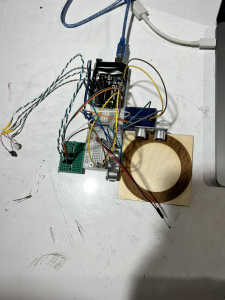
For a proof of concept, I have built a smaller version with one ultrasonic for each x and y components of the stove top. There are only two vibration motors as well just to show the possibility. In a real version of the concept, the vibration motors would be placed in a resonating surface such as a bell to create more noise and alert the user better.

Top down view of entire setup


Demo:


Code:

//Temperature stuff
const int tempSensor = A0;
float stoveTemp;
float stoveTempThreshold = 40; // [*C]
float c1 = 1.009249522e-03, c2 = 2.378405444e-04, c3 = 2.019202697e-07;


//Vibration motor stuff
const int vibrationMotor1 = 6;
const int vibrationMotor2 = 7;
const int vibrationMotorCount = 2;
int vibrationMotors[vibrationMotorCount] = {vibrationMotor1, vibrationMotor2};


//Object detection stuff
const int trigPin1 = 12;
const int echoPin1 = 13;
const int trigPin2 = 8;
const int echoPin2 = 9;
float dangerDistance = 5; //Distance threshold


//E-stop stuff
const int stopButton = 3;


//Logical stuff
bool stoveIsHot;
bool objectOnStove;
bool userOverride = false;


//Debounce Stuff
unsigned long debounceTimer = 0;
unsigned long debounceDelay = 100;
bool prevButtonState = false;
bool currButtonState = false;
bool lookForPress = true;


void setup()
{

  pinMode(trigPin1, OUTPUT); // Sets the trigPin as an Output
  pinMode(echoPin1, INPUT); // Sets the echoPin as an Input
  pinMode(trigPin2, OUTPUT); // Sets the trigPin as an Output
  pinMode(echoPin2, INPUT); // Sets the echoPin as an Input
  pinMode(tempSensor, INPUT);
  pinMode(stopButton, INPUT_PULLUP);

  pinMode(vibrationMotor1, OUTPUT);
  pinMode(vibrationMotor2, OUTPUT);

  attachInterrupt(digitalPinToInterrupt(stopButton), stopNoise, LOW);

  Serial.begin(9600); // Starts the serial communication

}

void loop()
{

  if (prevButtonState != currButtonState) {
    debounceTimer = millis();
    prevButtonState = currButtonState;
  }

  if (millis() - debounceTimer > debounceDelay) {
    lookForPress = true;
  }


  if (!userOverride) {
    stoveIsHot = checkStoveTemp();

    if (stoveIsHot) {
      objectOnStove = checkStoveSpace();
    }
  } else {
    vibrateMotors(0);
  }


}


int getDistance(int trigPin, int echoPin) {

  long duration;
  int distance;

  // Clears the trigPin
  digitalWrite(trigPin, LOW);
  delayMicroseconds(2);
  // Sets the trigPin on HIGH state for 10 micro seconds
  digitalWrite(trigPin, HIGH);
  delayMicroseconds(10);
  digitalWrite(trigPin, LOW);
  // Reads the echoPin, returns the sound wave travel time in microseconds
  duration = pulseIn(echoPin, HIGH);
  // Calculating the distance
  distance = duration * 0.034 / 2;
  // Prints the distance on the Serial Monitor
  return distance;

}


bool checkStoveTemp() {

  const int stoveTempThreshold = 40;
  static float stoveTemp;
  static bool DANGER;

  stoveTemp = analogRead(tempSensor);
  stoveTemp = log(stoveTemp);
  stoveTemp = (1.0 / (c1 + c2 * stoveTemp + c3 * stoveTemp * stoveTemp * stoveTemp));
  stoveTemp = stoveTemp - 353.15;
  //Serial.println(stoveTemp);


  if (stoveTemp > stoveTempThreshold) {
    if (!DANGER) {
      DANGER = true;
      Serial.println("WARNING...DANGER!!");
    }
  } else {
    if (DANGER) {
      DANGER = false;
      Serial.println("Surface is safe to touch now");
    }
  }

  return DANGER;
}


bool checkStoveSpace() {

  static bool moveHand = false;
  static const int numberOfDistanceSensors = 2;
  static float distanceReadings[numberOfDistanceSensors];
  static int distanceSensorPins[2 * numberOfDistanceSensors] = {trigPin1, echoPin1, trigPin2, echoPin2};


  //Check ultrasonic rangers
  for (int i = 0; i < numberOfDistanceSensors; i++) {
    int currTrig = distanceSensorPins[2 * i];
    int currEcho = distanceSensorPins[2 * i + 1];
    distanceReadings[i] = getDistance(currTrig, currEcho);
  }


  //Indicate danger if something is close to stove
  for (int i = 0; i < numberOfDistanceSensors; i++) {
    if (distanceReadings[i] < dangerDistance) {

      Serial.println("MOVE YOU HAND!!");

      //Make warning noise
      vibrateMotors(1);

      return true;

    }
  }


  //Turn off warning noise
  vibrateMotors(0);


  return false;
}

void vibrateMotors(int vibrationSpeed) {
  for (int i = 0; i < vibrationMotorCount; i++) {
    digitalWrite(vibrationMotors[i], vibrationSpeed);
  }
}


void stopNoise() {

  if (lookForPress) {
    currButtonState = !currButtonState;
    lookForPress = false;

    if (userOverride) {
      userOverride = false;
    } else {
      userOverride = true;
    }

  }

}


Crit1 Development: Stepper Motor Progress

I have 2 alternatives to power the turning plant- a DC motor or a stepper motor. I have run through a test of a DC motor (attached to a fan) and 2 tests for a stepper motor. I was inclined to try to use the stepper motor, but neither of the stepper motor tests have worked. It appears that the power supply module I’m using (which is supposed to be compatible with the driver and stepper motor I’m using) is failing to provide power to the driver and the stepper motor. Not clear yet where the failure is happening, although the dim LED light on the power supply module suggests that the 9V battery power supply I am using is not adequate. I will need to test another power supply to see if I can get the stepper motor to work. Since the DC motor with fan seemed to have varying success depending on the speed, I tried two stepper motor tests just in case a difference in the speed would make the stepper motor move.

UPDATE 2/28: With a new power supply (wall plug), the stepper motor code is working. Next step is to make a sketch that combines the stepper motor and the light sensor TEMT6000.

Stepper Motor Test 1 Sketch:

#include <Stepper.h>
int stepsPerRevolution=2048; //see motor spec sheet
int motSpeed=10;
int dt=500;
Stepper stepmot(stepsPerRevolution, 8,10,9,11);//see motor and driver specs

void setup() {
  // put your setup code here, to run once:
  Serial.begin(9600);
  stepmot.setSpeed(motSpeed);

}

void loop() {
  // put your main code here, to run repeatedly:
  stepmot.step(stepsPerRevolution);
  delay(dt);
  stepmot.step(-stepsPerRevolution);
  delay(dt);


}

Stepper Motor Test 2 Sketch:

#include <Stepper.h>
const float STEPS_PER_REV=32; //see motor spec sheet
const float GEAR_RED = 64;
const float STEPS_PER_OUT_REV = STEPS_PER_REV * GEAR_RED;
int stepsReq;
int motSpeed=10;
int dt=500;
 
Stepper steppermotor(STEPS_PER_REV, 8,10,9,11);//see motor and driver specs

void setup() {
  // put your setup code here, to run once:
  Serial.begin(9600);


}

void loop() {
  // put your main code here, to run repeatedly:
  steppermotor.setSpeed(1);
  stepsReq=4;
  steppermotor.step(stepsReq);
  delay(2000);

  stepsReq = STEPS_PER_OUT_REV / 2;
  steppermotor.setSpeed(100);
  steppermotor.step(stepsReq);
  delay(1000);


}


Crit1 Development: Experiment with Fan Motor and Light Sensor TEMT6000

With the TEMT6000 light sensor, I can turn on a motor based on input to the light sensor, similar to the one I had with the DHT-22.

With the TEMT6000, I used an analog write (instead of the digital write with the DHT-22) and the data arrives in float form. Several lines of code convert the reading into a percent. Data smoothing and millis () set up are the same as previous DHT-22 code.

#define lightPin A0 //Ambient light sensor reading 

//data smoothing
const int numReadings = 5;
float ligReadings [numReadings];
int ligReadIndex = 0;
float ligTotal = 0;
float ligAverage = 0;
int inputPin = lightPin; //put sensor pin here
//detecting sensor change
int last;
//response to sensor change

//for fan and motor
int speedPin = 5;
int dir1 = 4;
int dir2 = 3;
int mSpeed = 0;
unsigned long lastReadTime = 0;

void setup() {
  // put your setup code here, to run once:
  //pins for fan and motot
  pinMode(speedPin, OUTPUT);
  pinMode(dir1, OUTPUT);
  pinMode(dir2, OUTPUT);
  pinMode(lightPin, INPUT);

  for (int thisReading = 0; thisReading < numReadings; thisReading++) {
    ligReadings[thisReading] = 0;
  }
  Serial.begin(9600);
  lastReadTime = millis();
}

void loop() {
  //delay(1000);

  if ((millis() - lastReadTime) >= 5000UL) {
    Serial.println(lastReadTime);
    Serial.println(millis());
    lastReadTime = millis();
    //light sensor read
    float light = analogRead(lightPin);
    float light_ratio = light / 1023.0;
    float light_percent = light_ratio * 100;

    ligTotal = ligTotal - ligReadings[ligReadIndex];
    ligReadings[ligReadIndex] = light_percent;
    ligTotal = ligTotal + ligReadings [ligReadIndex];
    ligReadIndex = ligReadIndex + 1;
    if (ligReadIndex >= numReadings) {
      ligReadIndex = 0;
    }
    ligAverage = ligTotal / numReadings;
    Serial.println(light_percent);
    Serial.println(ligAverage);

  }


  if (ligAverage > 25)
  {
    digitalWrite(dir1, HIGH);
    digitalWrite(dir2, LOW);
    analogWrite(speedPin, 225);
  }else
  {
    digitalWrite(dir1,HIGH);
    digitalWrite(dir2,LOW);
    analogWrite(speedPin, 0);
  }
}

Next, I plan to use the sensor to turn another motor (the stepper motor, which I think is a better fit for turning the plant turntable).

Crit1 Development: Experiment with Button and p5js

I ran into challenges with the previous DHT22 sensor to p5js assignment. I performed another test run using input from a button. With this, I was able to connect the p5.js web editor to the arduino, and have an image on the screen of the web editor change when the button input changed.

Arduino sketch below:

const int buttonPin = 2;
int buttonValue = 0; 

void setup() {
  // put your setup code here, to run once:
  pinMode(buttonPin, INPUT);
  Serial.begin(9600);

}

void loop() {
  // put your main code here, to run repeatedly:
  buttonValue = digitalRead(buttonPin);
  Serial.println(buttonValue);
  delay(10);

}

p5js sketch:

let serial; 
let newData = "waiting for data";

function setup() {
  createCanvas(windowWidth, windowHeight);
  serial = new p5.SerialPort();
  serial.list();
  serial.open('COM5');
  serial.on('connected', serverConnected);
  serial.on('list',gotList);
  serial.on('data',gotData);
  serial.on('error',gotError);
  serial.on('open',gotOpen);
  
}

function serverConnected() {
  print("Connected to Server");
}

function gotList(thelist) {
  print("List of Serial Ports:");
  
  for (let i=0; i < thelist.length; i++) {
    print(i + " " + thelist[i]);
    
  }
}

function gotOpen() {
  print("Serial Port is Open");
}

function gotClose() {
  print("Serial Port is Closed");
  newData = "Serial Port is Closed";
}

function gotError(theerror) {
  print(theerror);
}

function gotData() {
  let currentString = serial.readLine();
  trim(currentString);
  if (!currentString) return;
  console.log(currentString);
  newData = currentString;
}

function draw() {
  background(245,245,245);
  fill(50,50,200);
  text(newData,10,10);
  
  
  if (newData == 0) {
    rectMode(CENTER);
    rect(width/2,height/2,100,100);
  } else {
    ellipse(width/2,height/2,200,200);
    
  }
  
}

Next, for the Crit1 project, I want to be able to record or represent the actions of the plant turntable with p5js.

Resources and Demos:


Assignment 6 Update

With the wires back on the fan motor, I confirmed that code works in two ways: 1) when the humidity sensor detects that the average humidity is less than 50% the fan turns on, and 2) when the average humidity is less than 50% the fan turns off. Next, with condition 2 as the base conditions, I needed to test if the fan will turn on when the humidity sensor detects that the average humidity has increased to above 50%.

With my first version of the code, the fan was not responding the way I wanted to the humidity sensor readings.

This second version of the code using millis() was successful:

#include <DHT.h>
#include <DHT_U.h>
#define DHTPIN 2        // sensor DHT22 data connected to Arduino pin 2
#define DHTTYPE DHT22  // using sensor DHT22
DHT dht(DHTPIN, DHTTYPE);  //dht library
int chk;
int humid; //stores humidity


//data smoothing
const int numReadings = 5;
int humReadings [numReadings];
int humReadIndex = 0;
int humTotal = 0;
int humAverage = 0;
int inputPin = 2; //put dht 222 sensor pin here
//detecting sensor change
int last;
//response to sensor change


//for fan and motor
int speedPin = 5;
int dir1 = 4;
int dir2 = 3;
int mSpeed = 0;
unsigned long lastReadTime = 0;

void setup() {
  // put your setup code here, to run once:
  //pins for fan and motot
  pinMode(speedPin, OUTPUT);
  pinMode(dir1, OUTPUT);
  pinMode(dir2, OUTPUT);


  //dht sensor
  dht.begin();

//data smoothing for humidity
  for (int thisReading = 0; thisReading < numReadings; thisReading++) {
    //tempReadings[thisReading] = 0;
    humReadings[thisReading] = 0;
  }
  Serial.begin(9600);

  lastReadTime = millis();
}

void loop() {
  //delay(1000);

  if ((millis() - lastReadTime) >= 10000UL) {
    //Serial.println(lastReadTime); //used to check millis 
    //Serial.println(millis());//used to check millis
    lastReadTime = millis();
    humid = dht.readHumidity();
    Serial.println(humid); //prints the current sensor reading
    humTotal = humTotal - humReadings[humReadIndex];
    humReadings[humReadIndex] = humid;
    humTotal = humTotal + humReadings [humReadIndex];
    humReadIndex = humReadIndex + 1;
    if (humReadIndex >= numReadings) {
      humReadIndex = 0;
    }
    humAverage = humTotal / numReadings;
    Serial.println(humAverage);

  }


  if (humAverage > 50)
  {
    digitalWrite(dir1, HIGH);
    digitalWrite(dir2, LOW);
    analogWrite(speedPin, 225);
  }else
  {
    digitalWrite(dir1,HIGH);
    digitalWrite(dir2,LOW);
    analogWrite(speedPin, 0);
  }
}

I started in a room with humidity readings less than 50 (no fan motion). I turned on hot water in the bathroom, and after a few minutes, moved the sensor and fan into that room. As the sensor’s humidity reading rose, so did the average humidity reading. Once the average humidity reading rose above 50, the fan began to turn. Then I moved the sensor and fan back into the original room, and waited for the average humidity to fall. When the average humidity fell below 50 again, the fan motor turned off.

Note on power and troubleshooting:

I originally had both the fan and the humidity sensor connected to the rail. This worked the first time I tried it, but the sensor began to send back 0 readings after a few test runs. I had to connect the DHT22 sensor to the arduino and the fan to the rail (with 5V power supply connected to 9V battery) for both the sensor and the fan to work properly. My clue was that the LED light on the power supply started bright and dimmed as the code started running.