Assignment 4: DHT 22 Temperature Sensor and LED

Before adding p5js to the operation, I set up a first iteration of input and output in Arduino.

The intention of the project is to measure environmental conditions and cue an alert when environmental conditions exceed a desired limit (too hot or too cold). This could have applications as a monitoring device during excessive heat waves. Based on temperature input from the sensor, the arduino  turns on a blinking warming light at a set temperature limit. For those seeking to use air-conditioning to a bare minimum (and save $), this system could act as a gauge that advises on serious conditions. Especially if someone is reliant on a window unit A/C instead of central air-conditions, it may encourage someone to seek a cooler environment and avoid risk of heat stroke.

I used the sensor to capture temperature data in warm and cold spots in my apartment. At the time measured, there was about a 7 degree F difference between the kitchen (~72 degrees F) and the bedroom (~65 degrees F). Since this was the temperature differential currently present in my apartment, I used tempF>= 70 to test the code, moving between rooms. In the kitchen, the LED light blinked, indicating the temperature was equal to or greater than 70 degrees F (I also used the Arduino serial monitor to check readings as I moved around).
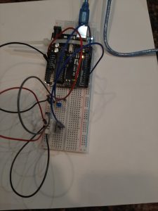
 

^DHT 22 Temperature and Humidity Sensor and LED

//

#include "DHT.h"   //adafruit dht library 
#define DHTPIN 2        // sensor DHT22 data connected to Arduino pin 2
#define DHTTYPE DHT22  // using sensor DHT22

DHT dht(DHTPIN, DHTTYPE);  //dht library 
int chk;
float humid; //stores humidity
float tempC; //stores temperature
float tempF; //stores temp in F
int blueled=10;


void setup() {
  pinMode(blueled, OUTPUT);
  Serial.begin(9600);
  dht.begin();


}

void loop() {
  //read dht22 data and store to variables humid and temp
  if (isnan(humid) || isnan(tempC) ||isnan(tempF)){
    Serial.println(F("Failed to read from DHT sensor"));
    delay(10000);
    return;
  }
// troubleshooting issues with getting nan reading from dht22
  humid=dht.readHumidity();
  tempC=dht.readTemperature();
//converting to fahrenheit
  tempF=(tempC*1.8)+32;
//printing temp and humid values to serial monitor
  Serial.print("Humidity: ");
  Serial.print(humid);
  Serial.print(" %, Temp: ");
  Serial.print(tempF);
  Serial.println("Fahrenheit");
  delay(2000);
  if (tempF >= 70){
    digitalWrite(blueled,HIGH);
    delay(150);
    digitalWrite(blueled,LOW);
    delay(75);
  }
 delay(2000); 


}

Arduino was a success. The LED light blinked on and off when temperature was above 70, and stayed off when temperature was less than 70.

When I connected the p5.serial control, the console was printing out the serial print that had been set up on the arduino:
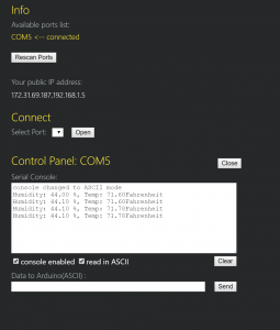
^first, I thought I would break out the second part of the arduino code (the control of the LED light) as data sent to arduino via p5. serial control. The library for DHT22 is all C++ and not clear to me initially how to modify. So as a first step, I tried to print sensor data on p5js.

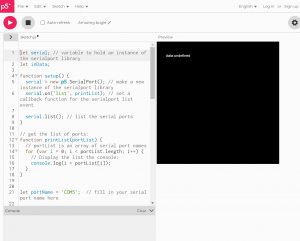
Reviewed two arduino/potentiometer/P5js tutorials (https://medium.com/@yyyyyyyuan/tutorial-serial-communication-with-arduino-and-p5-js-cd39b3ac10ce, https://itp.nyu.edu/physcomp/labs/labs-serial-communication/lab-serial-input-to-the-p5-js-ide/#Draw_a_Graph_With_the_Sensor_Values). I thought it would be interesting to use the information from the sensor to draw a graph, which would highlight changes in temperature or humidity. There was a lot that needed to be done to set up serial port, not sure if this is where everything went wrong, and my final result was undefined. I am wondering if this has to do with the DHT22 library being all C++ or if DHT 22 values need to be mapped to 0 to 255 before this information is read by P5 serial.
 

let serial; // variable to hold an instance of the serialport library
let inData;
 
function setup() {
  serial = new p5.SerialPort(); // make a new instance of the serialport library
  serial.on('list', printList); // set a callback function for the serialport list event
 
  serial.list(); // list the serial ports
}
 
// get the list of ports:
function printList(portList) {
  // portList is an array of serial port names
  for (var i = 0; i < portList.length; i++) {
    // Display the list the console:
    console.log(i + portList[i]);
  }
}


let portName = 'COM5';  // fill in your serial port name here
 
function setup() {
  serial = new p5.SerialPort();       // make a new instance of the serialport library
  serial.on('list', printList);  // set a callback function for the serialport list event
  serial.on('connected', serverConnected); // callback for connecting to the server
  serial.on('open', portOpen);        // callback for the port opening
  serial.on('data', serialEvent);     // callback for when new data arrives
  serial.on('error', serialError);    // callback for errors
  serial.on('close', portClose);      // callback for the port closing
 
  serial.list();                      // list the serial ports
  serial.open(portName);              // open a serial port
}

function serverConnected() {
  console.log('connected to server.');
}
 
function portOpen() {
  console.log('the serial port opened.')
}
 
function serialEvent() {
  inData=Number(serial.read());
 
}
 
function serialError(err) {
  console.log('Something went wrong with the serial port. ' + err);
}
 
function portClose() {
  console.log('The serial port closed.');
}

function setup() {
  createCanvas(400, 400);
}


function draw() {
  background(0);
  fill(255);
  text("data:"+ inData, 30, 50)
}


My references include:

https://www.arduino.cc/reference/en/libraries/dht-sensor-library/

https://stackoverflow.com/questions/40874880/getting-nan-readings-from-dht-11-sensor

https://create.arduino.cc/projecthub/mafzal/temperature-monitoring-with-dht22-arduino-15b013

https://www.instructables.com/How-to-use-DHT-22-sensor-Arduino-Tutorial/

https://itp.nyu.edu/physcomp/videos/videos-serial-communication/#Serial_to_p5js_in_binary

How to Set Up the DHT11 Humidity Sensor on an Arduino

Notes-

When looking for DHT22 and p5js, this project came up: https://github.com/TTurbo0824/pcom_final/blob/master/test_led_hum_serial.ino

^has a note for incorporating p5js but this just looks like what got uploaded to arduino, not additional p5js data sent


** 2/08/2022 Update:

Serial port appears now to be connected to P5JS. I was able to use the test sketch from last week to check that the values for temperature (in C) came through, then both values for temperature and for humidity.

HOWEVER, while running the sketch in the browser editor, the data from the serial port is not registering.

New P5JS sketch:

let serial; // variable to hold an instance of the serialport library
let portName = 'COM5'
let inData;
 
function setup() {
  createCanvas(400,300);
  background('rgba(0,255,0, 0.15)');
  

}

  serial = new p5.SerialPort(); // make a new instance of the serialport library
  serial.on('list', printList); // set a callback function for the serialport list event
 
  serial.list(); // list the serial ports

 
// get the list of ports:
function printList(portList) {
  // portList is an array of serial port names
  for (var i = 0; i < portList.length; i++) {
    // Display the list the console:
    console.log(i + portList[i]);
    serial.on('list',printList);
    serial.on('connected', serverConnected); // callback for connecting to the server
  serial.on('open', portOpen);        // callback for the port opening
  serial.on('data', serialEvent);     // callback for when new data arrives
  serial.on('error', serialError);    // callback for errors
  serial.on('close', portClose);      // callback for the port closing
    
    
serial.open(portName);              
    // open a serial port
    
  function serverConnected() {
  console.log('connected to server.');
}
 
function portOpen() {
  console.log('the serial port opened.')
}
 
function serialEvent() {
  inData = Number(serial.read());
 
}
 
function serialError(err) {
  console.log('Something went wrong with the serial port. ' + err);
}
 
function portClose() {
  console.log('The serial port closed.');
}

    
  }
 

  function graphData(newData) {
  var yPos=map(newData,0,255,0,height)
  stroke(0xA8,0xD9,0xA7);
  line(xPos,height,xPos,height - YPos);
  if (xPos>=width) {
    xPos=0;
    background(0x08, 0x16, 0x40);
  } else {
    xPos++;
  }
  }  
 function draw() {
  graphData(inData);
  text("temperature in Celsius:" + inData, 1, 50);
  
} 
  
}


Assignment 4: Interaction with p5.js and Arduino

Create accessibility using an Arduino, sensors, p5.js, and a screen.

The context is you’re making something accessible or usable. We’re still in the early days so this can be rather abstract or a proof of concept.

Two parts to the assignment which can be implemented as two different sets of sketches.  If you can do both in one set of sketches, that’s great.

Use Arduino inputs to display something in a p5.js sketch.  A very simple example is a switch on the Arduino that detects a door being opened, and the Arduino asks the p5.js script to go from dark to light.

Use a p5.js sketch interract to make something happen on the Arduino: turn LEDs on/off, spin a motor, etc.  Imagine p5.js is a touch-screen and you’re making things happen across the room.

Due Monday, 7 Feb 2022, 11:59 pm.  We will discuss on Tuesday.

Class notes 1 Feb, p5.js example

Hi,

I’ve asked for replacement Teensy Arduinos, I’m not sure if they will be here before class on Thu.

Please work on getting p5.js talking to your Arduino.  I have mine working on Win10 without NPM.  Here’s simple sketches for p5.js and Arduino.  Remember that you have to disconnect p5.serialconnect before you can upload and Arduino sketch.  On your browser (I use firefox), you might need to shift-reload the p5.js sketch to get it working again.

example-20220201.tar.gz


Fun With Interrupts – James Kyle

How it works:

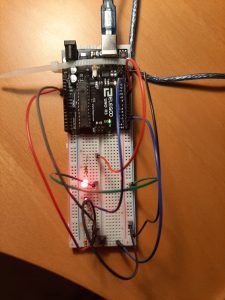
I played around with buttons switches and potentiometers to change light blinking patterns and came up with this circuit. The switch has an interrupt which changes whether all lights blink at the same time or different times (a blink mode). The button changes which light blinks in the event that they are not blinking at the same time. The potentiometer changes the speed at which the lights blink.

I had some trouble with getting the switch interrupt to work more than once and I ended up having to place it before the button interrupt which I assume prioritizes it.


Code:

int toggle_color = 3;
int GREEN_LED = 7;
int YELLOW_LED = 6;
int RED_LED = 5;
int POT = A0;
int blink_rate = 250;
int toggle_blinkMode = 2;


//LED blinking variables
volatile int LED_pin = 5;
volatile bool individual_blink;


//Debounce variables
volatile unsigned long last_press = 0;
int wait_time = 50;


void setup() {

  Serial.begin(9600);

  //Initializing Pins
  pinMode(GREEN_LED, OUTPUT);
  pinMode(YELLOW_LED, OUTPUT);
  pinMode(RED_LED, OUTPUT);

  pinMode(toggle_color, INPUT_PULLUP);
  pinMode(POT, INPUT);


  //Interrupt initialization
  attachInterrupt(digitalPinToInterrupt(toggle_blinkMode), blinkMode, CHANGE);
  attachInterrupt(digitalPinToInterrupt(toggle_color), switchLED, CHANGE);


}

void switchLED() {

  //Turn off previous light
  digitalWrite(LED_pin, LOW);

  //Debounce
  if ((millis() - last_press) >= wait_time) {
    LED_pin++;
    last_press = millis();
  }

  //Go back to first light
  if (LED_pin > 7) {
    LED_pin = 5;
  }


}

void blinkMode() {

  if (individual_blink) {
    individual_blink = 0;
  } else {
    individual_blink = 1;
  }

}

void loop() {

  blink_rate = map(analogRead(POT), 0, 255, 100, 500);

  if (individual_blink) {
    digitalWrite(LED_pin, HIGH);
    delay(blink_rate);
    digitalWrite(LED_pin, LOW);
    delay(blink_rate);
  } else {
    digitalWrite(RED_LED, HIGH);
    digitalWrite(GREEN_LED, HIGH);
    digitalWrite(YELLOW_LED, HIGH);
    delay(blink_rate);
    digitalWrite(RED_LED, LOW);
    digitalWrite(GREEN_LED, LOW);
    digitalWrite(YELLOW_LED, LOW);
    delay(blink_rate);
  }

  bool value = individual_blink;
  Serial.println(value);


}


Messing Around With Interrupts

Messing Around With Interrupts:

Functionality:

There are two different states that the system can be put into. These states are controlled by an interrupt connected to the switch. When the switch is high, the system goes into adjustment mode where the user can use the potentiometer to adjust the brightness of the LED. This adjustment is only possible while in this state. When the switch is low, the system returns to its normal state where there is a blinking mode and solid mode. These modes are controlled by a second interrupt tied to the button. While in the blinking state, the LED’s flash individually for 0.5s each in a sequence of red to yellow to green and back to red. In the solid state, all of the LED’s remain on. The brightness of the LED’s in this mode is also the same as that set in the previous adjustment state.

Code:
/*  Interrupt Assignment 
 *  Judson Kyle 
 *  judsonk 
 *  01/31/2021 
*/
#define POT_PIN     A0
#define SWITCH      3
#define BUTTON      2

#define RED_LED     11
#define YELLOW_LED  10
#define GREEN_LED   9

#define RED     0
#define YELLOW  1
#define GREEN   2

volatile bool ADJUST_STATE = false;
volatile bool BLINK = false;

int potVal = 0;
double ledBrightness;

int currentLED = 0;

int waitTime = 500; //ms
long long startTime;

int buttonDebounceTime = 300;
long long buttonDebounceStart = 0;
volatile bool BUTTON_DEBOUNCE = false;
bool BUTTON_PREV_DEBOUNCE = false;


void setup() {
  
  pinMode(POT_PIN, INPUT);
  pinMode(SWITCH, INPUT);

  //Interrupts
  attachInterrupt(digitalPinToInterrupt(BUTTON), handleButton, RISING);

  //LED's
  pinMode(RED_LED, OUTPUT);
  pinMode(YELLOW_LED, OUTPUT);
  pinMode(GREEN_LED, OUTPUT);

  Serial.begin(9600);

}

void handleButton() {
  if (!BUTTON_DEBOUNCE) {
    BUTTON_DEBOUNCE = true;
    BLINK = !BLINK;
  }
}

void loop() {

  //Read switch state
  ADJUST_STATE = digitalRead(SWITCH);
  Serial.println(ADJUST_STATE);
  
//  Serial.print("DEBOUNCE: \t");
//  Serial.print(DEBOUNCE);
//
//  Serial.print("\tdebounceStart: \t");
//  Serial.print((int)debounceStart);
//
//  Serial.print("\tTime Elapsed: \t");
//  Serial.println(millis() - (int)debounceStart);

  //Process switch logic
  if (ADJUST_STATE) {
    potVal = analogRead(POT_PIN);
    ledBrightness = (256*potVal)/1024;
    analogWrite(RED_LED, (int)ledBrightness);
    analogWrite(YELLOW_LED, (int)ledBrightness);
    analogWrite(GREEN_LED, (int)ledBrightness);
  }

  //Change brightness of LED based off potentiometer switch when not in blink mode
  if (BLINK) {
    if (millis() - startTime > waitTime) {
      startTime = millis();
      currentLED++;
      if (currentLED >= 3) {
        currentLED = 0;
      }
    }
    
    switch(currentLED) {
      case RED:
        analogWrite(RED_LED, (int)ledBrightness);
        analogWrite(YELLOW_LED, LOW);
        analogWrite(GREEN_LED, LOW);
        break;
      case YELLOW:
        analogWrite(RED_LED, LOW);
        analogWrite(YELLOW_LED, (int)ledBrightness);
        analogWrite(GREEN_LED, LOW);
        break;
      case GREEN:
        analogWrite(RED_LED, LOW);
        analogWrite(YELLOW_LED, LOW);
        analogWrite(GREEN_LED, (int)ledBrightness);
        break;
      default:
        break;
    }
  }
  else {  //If not in blinking mode make all LED's light up
    analogWrite(RED_LED, (int)ledBrightness);
    analogWrite(YELLOW_LED, (int)ledBrightness);
    analogWrite(GREEN_LED, (int)ledBrightness);
  }

  //Handle button debounce
  if (BUTTON_DEBOUNCE && !BUTTON_PREV_DEBOUNCE) {
    buttonDebounceStart = millis();
  }
  if (abs(buttonDebounceStart - millis()) > buttonDebounceTime) {
    BUTTON_DEBOUNCE = false;
  }
  BUTTON_PREV_DEBOUNCE = BUTTON_DEBOUNCE;
}


Images:

Interrupts

Interrupt, Switch Blinking LED from Red to Yellow

Experimented with some of the values.

Tested the button with pin13 before proceeding- button works.

Did not consistently get it to switch colors every time I pressed the button down.

First interrupt attempt (successful), includes questions:

int rLED=9;
int yLED=10;

int ledOn=5;

volatile int switch_color=2;

//see loop for onoff pattern, did other iterations with more complex onoff patterns, made it more difficult to cue the interrupt
int ledDelay=250;

void setup() {

  pinMode(rLED,OUTPUT);
  pinMode(yLED,OUTPUT);

  pinMode(switch_color,INPUT);
  attachInterrupt(digitalPinToInterrupt(switch_color),switchLed,FALLING);
//does rising or falling matter? maybe only needed with more than 2

  ledOn=rLED;

  Serial.begin(9600);
//does this impact the switch back to red from yellow?

}


void switchLed() {
    ledOn++;
    if (ledOn > yLED) {
        ledOn = rLED;
    }
}


void loop() {
//red LED turns on and off based on delay variable, then on for delay*10, and off for delay*5 before repeating
digitalWrite(ledOn,HIGH);
delay(ledDelay);
digitalWrite(ledOn, LOW);
delay(ledDelay);


}

Tangible Interface for Geospatial Modelling

http://tangible-landscape.github.io/#:~:text=Tangible%20Landscape%20is%20an%20open,by%20GRASS%20GIS%20and%20Blender.&text=This%20makes%20geographic%20information%20systems,developers%20%2D%20like%20gaming%20with%20GIS.

^Intended for education. I was reminded of this after reading about the dynamic sand table in Make It So.

Make It So Readings: how did we think about the future in the past? – Erin P

General Notes

-Science fiction technologies evolve as audiences become more sophisticated and informed by real technological advances.

-Real technology sets a bar for interface/technology expectations of sci-fi audiences – must go above and beyond present reality within believable bounds to distinguish itself from pure ‘magical fantasy.’

-Interface defined as ‘all parts of a thing that enable its use.’ Spans industrial design, information design, and interaction design.

-Interface evaluation (for purposes of this book) require media that is audiovisual, time-based, and consistent.

-Genre of media is speculative/science fiction, loose definition, not getting too into the weeds on definitions.

-Motorola’s StarTAC took cues from Star Trek communicator

-‘all design in fiction- at least until it gets built.’

Past Thoughts about the Future

-Ch. 1 touches on the reciprocal influence of speculative fiction technology and the real world, and examples of this from the past. The design ‘kitchen of the future’ came up in last class, would be curious to know more about the reciprocal relationship there. Read an article about the Frankfurt kitchen a few days ago: https://www.bloomberg.com/news/articles/2019-05-08/the-frankfurt-kitchen-changed-how-we-cook-and-live

-Interfaces have ‘legacies’ – buttons/knobs/switches (also appealing to use for human hand). Digital controls and touch screens are only recently available. New interfaces most understandable when they build on ones that users/audiences are familiar with.

-Industrial age paradigm: few mechanical controls (levers, buttons, knobs), direct, mechanical feedback via interfaces with ‘very little abstraction between cause and effect.’

-Electrical age paradigm: more mechanical controls, with people using levers/buttons/knobs everyday

-WWI brought vast numbers of people into contact with military technology- control rooms, radio and communications.

-Dedication to realism increased over time  (ex: restrained control board in Destination Moon, 1950).

-Low budget lead to the design of the touchscreen-esque interface in Star Trek: The Next Generation in 1980s – movement away from mechanical controls.

-Computation resulted in very abstracted feedback between cause and effect, with graphical user interfaces restoring greater sense of ‘direct manipulation’ for user.

-Virtual/mechanical control fix likely in fiction and in real life due to advantages of each, ie fine motor control for mechanical and complexity allowed by virtual.