Project 1: A Double Transducer
due Thursday, October 1st, at the start of class
Some definitions
The good people at the Oxford English Dictionary tell us that a transducer is “any device by which variations in one physical quantity (e.g. pressure, brightness) are quantitatively converted into variations in another (e.g. voltage, position).”
For this assignment, we’ll refer to a realm of related “physical quantities” as a domain. For instance, “sound” is the domain that encompasses things that either produce or sense vibrations traveling through a medium, and the domain “light” includes things that produce light (like LEDs) as well as light sensors.
A transducer is for us simply some device which changes an input signal in one domain (such as light, sound, vibration, magnetic field, etc.) into a related output signal in another domain.
The Double Transducer
The goal of this project is for each team to build a device which reads some input signal in a domain, then converts it into a signal in another domain, reads that second signal, and finally outputs a third signal, which is in a third different domain. Whereas a single transducer would change a signal from one domain to another, a “double transducer” will do that process twice in a row.
Our goal will be to “chain” as many of these transducers together as possible: ideally, at the crit in class, we’ll be able to see a single signal flow through each of the machines you make, in a row, head to tail. This will require some class-wide coordination—that’s why your input and output domains are being assigned.
Examples
A light-to-movement-to-sound machine
The user’s description of this double transducer might be: “When the light in the room gets brighter, a little motor moves and turns a little knob, and then the sound coming out of a speaker gets louder. When the light in the room gets dimmer, the opposite happens, and the sound gets quieter.”
To explain this device from its creator’s perspective:
- The first transducer takes as an input the light level in the room. It drives the position of a servomotor as its output—this transducer changes an input signal in the “light” domain to an output in the “mechanical/position” domain.
- The second transducer then reads the “mechanical/position” state of the hobby servo output using a potentiometer. It then uses the potentiometer’s value to adjust the volume level of a speaker, which is a “sound” output.
The chain of information through this double transducer could be shown like this:

light (sensed by a photocell) ⇒ mechanical position (driven by a motor)
→ mechanical position (sensed by a potentiometer) ⇒ sound (produced by a speaker)
Note that the ⇒ double arrows above show steps where the signal has been transduced across domains, and the → single arrow shows a step where an output in one domain is being read as an input in that same domain.
A position-to-light-to-vibration machine
A user’s description: “When the machine gets closer to an object, it shines less light on a sensor, and then a small motor vibrates more. When the machine gets farther from an object, it shines more light on a sensor, and the motor vibrates less.”
The two transducers:
- The first transducer uses an ultrasonic ranger to detect the proximity of an object to the machine. When it detects a closer object, it makes an LED get dimmer; when it detects something farther away, it gets brighter.
- The second transducer measures the light coming off of that LED. When it sees a brighter light, it makes a small vibration motor move less, and when it sees a dimmer light, it makes the motor vibrate more.
The information chain of this double transducer could be shown like this:

position (detected by an ultrasonic ranger) ⇒ light (produced by an LED)
→ light (measured by a photocell) ⇒ mechanical vibration (produced by a vibratory motor)
Anti-example: a temperature-to-sound-to-temperature machine
This is an example of a transducer that does not satisfy this assignment’s prompt.
A user’s description: “When the thermometer detects a higher temperature, it makes a speaker get louder. When the microphone hears that louder sound, it turns on a heater. On the other hand, when the thermometer detects a lower temperature, the speaker gets quieter, and the heater turns down too.”
The problem here is that the input domain of the first transducer (which is temperature⇒sound) is the same as the output domain of the second one (which is sound⇒temperature). All three domains in the machine must be different. If the output of the second transducer were instead something like a laser changing brightness, then this would satisfy the assignment.
Final deliverable
Simulation vs. physically realized
Unfortunately, we’ve had to wait longer than ideal for students to get their course kit of parts; however, we are lucky that Tinkercad is already designed to accommodate collaboration at a distance through its “Share this design” feature.
This project will have two distinct deliverables in order to allow for maximum flexibility around fabrication. Each group will be responsible for building a Tinkercad circuit and submitting via URL as is the typical practice for homeworks, but each individual student will be responsible for physically building out their actual circuit as well. While the Tinkercad circuit has a fixed due date, the physical circuit can be handed in later than that date, by any student who hasn’t gotten their kit in time to be able to build it out.
Note on faking the middle-step in the simulator
In the real world, if you put an LED facing into a photoresistor, when the LED shines more light on it, the photoresistor will have more light hitting it and change its resistance. In the real world, you can tape a servo motor’s output to a potentiometer shaft. In the real world, things physically affect each other! In the Tinkercad simulator, that’s not the case.
For this reason, you should include a short section of code in your Tinkercad model, which will be different from your actually-physically-built model. This code will allow the middle-step input to “read” whatever value it should be reading, directly from the middle-step output. For instance, if your middle step is an LED shining at a photoresistor, you might in the real world have something like:
analogWrite(LED, ledVal); // LED shining at photoresistor
photoVal = analogRead(PHOTOPIN);
which will work fine when the actual components are facing each other physically. But in Tinkercad, you’ll need to “fake this”, e.g.:
/* faking transduction in software as simulator doesn't simulate it
analogWrite(LED, ledVal); // LED shining at photoresistor
photoVal = analogRead(PHOTOPIN);
*/
photoVal = map(ledVal, a, b, c, d); // faking the sensing for simulation
where a, b, c, d are whatever values that make sense for your setup.
Physical arrangement
Your transducer should be physically situated on a piece of cardboard/hardboard (which is included in your kit), with its input sensor elevated 1” off the surface centered on one edge, and its output delivered 1” off the surface centered on the opposite edge. The middle step of the device can be wherever you’d like. (The purpose of this standardization is to allow for multiple transducers to be placed right next to each other, to physically move a signal along the chain.)
It is acceptable for your device to need external power, but battery power is preferable if possible. The LCD display should be centered on the side facing the user (i.e. with the input to its left and output to its right).
Labeling
The different steps of transduction should be labeled in writing on the cardboard surface (or other paper/etc. affixed to the surface) so that your classmates and others can look at your transducer and read what each step is doing. The labels (which may be hand-written) should name and very briefly describe each sensor or actuator, e.g.:
Photoresistor
This device’s electrical resistance changes based on the amount of light hitting it.
or
Servo motor
The Arduino transmits position-control pulses to this device to command it to move its output arm to a specific degree position.
Status display
You should employ an LCD display, preferably 16×2 though 20×4 is also acceptable, to give any viewer an active update of the status of both of the sensors as well as both of the actuators. The displayed value of each sensor’s or actuator’s state should be normalized to a range of 0–99 for ease of reading (for instance: though a potentiometer may have actual values 0–1023 on the Arduino, you should remap that range to a minimum 0 and maximum 99). The display should follow a particular formatting scheme which shows the input sensor’s value on the upper left of the screen; the middle-step actuator value in the center top of the screen; the middle-step sensor value in the center bottom of the screen, and the output actuator’s value in the lower right of the screen. For instance:
i:58  m:59
        60  o:62
0123456789012345
Notes on this display:
- The grey numbers beneath the display are there for your reference; they show which column each value or label should align on. Note that the first column is labeled
0and the last one is15. You don’t need to display the column numbers! (Nor could you; the 16×2 display only has space for two rows of text.) - The
istands for “input,” themstands for “middle step,” and theostands for “output.” We have to use such short abbreviations for everything because the display is only 16 characters wide! - To be explicit about what this display is representing: The device’s input sensor’s value is being normalized (mapped) to 58; the middle step’s actuator value is being mapped to 59; the middle step’s sensor value is being mapped to 60, and the final output actuator’s value is being mapped to 62. In practice, if your transducer is working right, all of these numbers will be maintained close to each other (if the input is 59, then the output should be about 59 as well).
- Please see the I²C LCD tutorial, and in particular the example code included there, for information about how to align text on the screen in particular positions. While that page pertains to an I²C LCD specifically (and your kit has a more standard multi-pin LCD), outside of the different I²C LCD setup function, the rest of the commands are the same and should work across both models of display.
- The display should update 4–10 times per second.
Bonus fun remoteness
We’re going to experimentally try to get our transducers to communicate with each other through an internet protocol called MQTT; if it works, we might have successful transduction from coast to coast! Technical details of this, including a rehearsal, to be posted here later.
Progress check-in
(10% of project grade)
due Tuesday, Sept. 22nd, at the start of class
Submit the link to your Google Drive document via this Canvas assignment.
Prior to class, work with your partner(s) to come up with three ideas for what you’d like to make for this project. Flesh out each idea a bit and provide for each idea:
- a few sentences of narrative description,
- a mechanical/physical sketch of your proposed build, and
- an electrical schematic.
You should generate a Google Drive document to share and submit these things. We’ll discuss it in class and you’ll get written feedback afterwards as well.
Discussion and ideas
Usually when we instruct the Arduino to transduce one signal to another, its inner workings all happen electronically and invisibly. But by building the double transducer we add some interesting qualities: for one, some inner “state” of the machine is directly observable. That state may also quite possibly be fragile; the outside world, or the user herself, might reach in and directly affect the inner state. (For instance, if the inner state of the machine uses an LED paired with a light gauge, the user could shine extra light onto the machine.)
Another consequence of building an exposed link in the signal chain is that there is the possibilty that there will be some effect on the data that flows through the system. This effect might be filtering, noise, or both. In the light-to-movement-to-sound example above, the motor can’t move very quickly: so that will cause an unavoidable mechanical delay in the output of the system. It might also eliminate very small changes, since it probably won’t move in very small increments.
Groups
You’ll be assigned a partner for this project; pairings will be made as a Canvas announcement on 9/17. Partners work together and share the same credit for the Tinkercad assignment, including both code and the circuit. You can divvy up tasks how you’d like, but it should be something that both partners are comfortable with. If you are becoming frustrated or feel like you’re not going to be succeed in getting a project together with your assigned partner, speak with Zach as soon as possible so we can sort things out.
You will also be assigned (with your partner) a particular input and output domain for the machine you make; the third (middle) domain is entirely up to you.
Scope and Expectations
This assignment is given early in the semester, when there hasn’t been much time for technical learning. You’ll just be getting comfortable with simple circuits by the time the project comes due, and you’re not expected to build something very complex electronically or mechanically. Instead, you’re expected to think creatively and build something interesting that actually functions to transduce the assigned input signal to the assigned output signal.
For this project it is preferable to scope your work pragmatically and finish with a functioning machine rather than aiming for a very sophisticated outcome and falling short. Give yourself plenty of time to fail and iterate before the final crit!
It’s ok for your machine to look somewhat aesthetically sloppy, so long as it works—but if you can keep your wires/electronics/etc. on the neater side of things, it will make it easier and clearer for onlookers to understand the functioning. Build it out of cardboard, tape, straws, and hot glue if you want! Low-cost and easy-to-use materials are great and expected.
Tinkercad circuits should have good, clean wiring practices with straightened-out wires, sensible and legible parts layout, etc.
Documentation
Take pictures as you’re going along!
Your completed documentation is due at the beginning of class one week after the project is due, on Thursday, October 8th.
Why do you submit documentation?
The Arduino project was born, after some twists and turns, out of an Italian masters student’s thesis.1 He could have, one imagines, kept all those ideas to himself, started up a little factory, and sold them for €50 and called it a day. But the project has grown into a worldwide thing of beauty because the hardware designs (how to build an Arduino) and all of the underlying software (how to program one) are “open-sourced.” This means that anybody who wants to can see the community’s work and make their own version. Maybe even improve it themselves, and then suggest that their improvement might be something the community as a whole wants to adopt. Don’t believe me? Look at all these people contributing to the project’s Github page.
Think of how great it is for someone to see your cool project, get inspired, and build on it to make their own customized version. The answer is: very great! Having stood on the shoulders of others in the world of people making things, you can begin to return the favor by sharing the interesting ideas and technical insights you had.
Finally, we in IDeATe are interested in encouraging an introspective inquiry into your own process of ideation, creation, and revision. Just as writing an essay helps you understand your own argument on a topic better, documenting your own creative process will help you understand your creativity better. Documentation gives you insight to see what you got hung up on and what steps you wish you’d lingered on more. It opens a window onto your own process.
What to submit (documentation content requirements)
If you have any questions about the submissions requirements, or run into technical problems, be sure to contact the instructor before the due date.
Each documentation submission must consist of at least:
-
A “featured image” that is a good overall view of the project. This image will show up above the title of your project in the overview page. This image should be one of final project images described below, or a cropped subset of one of them. Select the featured image by clicking on “set featured image” in the right column of the post editing page.
-
The project title.
-
Decent images of the final projects. If it’s possible for you to take higher-quality image, like using a DSLR (here’s the class DSLR photography guide), that’s fine; but camera phone pictures are ok, too.
At least four images:- Brief screengrab movie in
.mp4format to embed in the documentation page which shows the Tinkercad machine working (i.e. reading an input which the user changes, passing the data internally, and then driving an output). We should be able to see the status changing by observing the LCD screen. See below for screengrab information. (one per team) - Overall photo for proportion and scale (one per team member)
- Detail photos of any part that you’d like to highlight (two to five between the team members)
- Brief movie in
.mp4format to embed in the documentation page which shows the machine working, i.e. reading an input, passing the data internally, and then driving an output (one per team member)
- Brief screengrab movie in
To make a screengrab movie of part of your screen:
- On a Mac: launch QuickTime Player, select File->New Screen Recording, and follow the on-screen prompts to select the area of the screen you wish to record. There is plenty of information online about how to convert the resulting
.movfile to an.mp4for posting.- On Windows: this article provides some useful pointers. The easiest option, Windows’s built-in screen recorder, will record your full screen (not ideal); the PowerPoint option is a good one if you’ve got that software on your machine; the OBS option is free to download if neither of the above work well for you (though it will require a tiny bit more setup).
- On Linux: there are many free and open-source options, as this article shows. OBS is a good prospect (I can vouch for it).
To add an
.mp4'video to your post, upload the file to the Media Library, and under the “Attachment Display Settings” dropdown, select “Embed Media Player” before clicking “Insert into post.” This will ensure that the video itself, rather than a link to the file, appears in your documentation.
Each image should be captioned. (To add captions in WordPress: click on an image, click on the pencil icon to edit it, write a caption, and click “update.”) The captions serve to explain both what the viewer is looking at, as well as elucidating some of the operating details of the object.
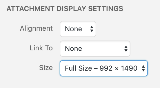
When uploading images, in the “Add Media” window, select “Full Size” under the “Attachment Display Settings” header, as shown below. (If you choose a smaller size, your images will be downsampled, potentially with very ugly and destructive results.)
-
Simple narrative description (one per team) of the thing and usual operation of the thing—the type of plain and straightforward description that you might write in a letter to a child to explain what you had made. Free of judgment and totally literal and straightforward. Try to use as little technical language as possible. (E.g. “A white plastic box has a switch on the top side. When the user turns it on, a green LED flashes five times showing that the system is ready. A small white flag waves back and forth.”) For a study in the art of using simple language, see Randall Munroe’s wonderful Up Goer Five. To use a simple-language filter yourself, try the Up-Goer Five text editor.
-
Four progress images (two per student), each of which could be a step or misstep that happened along the developent process, and each with at least a sentence or two caption. These images may capture decision points, especially interesting or illustrative mistakes, or other mileposts along the way. The idea is that these medium-quality images (though good pictures work too) are taken along the way to document progress. Sometimes you might understand these as being moments-that-matter only in retrospect! The safe route, therefore, is to snap lots of photos as you go along for later review.
-
Discussion (one per team) pertaining to process and outcome. For instance, what was easy, what was hard, what did you learn? What little tweak, in retrospect, would’ve changed the direction entirely? This is an opportunity for you to reflect on your creative and technical growth through the project, and think about what growth you want to aim for next. This shouldn’t be a recital of your process, but rather a meaningful reflection, 2–4 paragraphs in length.
-
Schematic (one per team), hand-drawn and scanned, or executed in software like Fritzing, EAGLE, in some flowchart application like draw.io, or any other way that produces a reasonably legible output. This should be done well enough that a competent person, reading the drawing and with the appropriate parts, could recreate the electrical system of the project. Note: Do not just draw the letter A with a rectangle around it to represent the Arduino. Write a more complete label for it, such as “Arduino Uno R3.”
-
Code submission (one per team), embedded into the project page, and optionally also with a Github or other version control service public-facing link. Your code should be reasonably commented throughout so that people other than you (the author) can better understand it. You don’t need to explain every single line—that would be overkill—but leave useful notes in a reasonable measure. Write a comment block at the top of the code which is different from the comment block that you use for homeworks:
- the project title,
- (optionally) your names,
- a description (short or long) of what the code does,
- a pin mapping table that would be useful to somebody else trying to recreate your work,
- appropriate credit to any other person’s/project’s code that you incorporated into your project, and
- (optionally) a license notice (i.e. copyright, CC BY-SA 4.0, the MIT License, release it to the public domain, or just follow your heart). If you have written code that you wish to keep strictly proprietary for any reason, please speak with the instructor about an exception to this documentation requirement.
Make sure that your final code as it appears on the public-facing post is correct and will compile!
To embed the code properly: on the WordPress “Edit Post” page, move your cursor to where the code should be inserted in your post. Click the “Code Insert” button in the toolbar above the post (it is marked
{…}). For Language, selectC. Paste the code—properly indented!!—into the window, and click OK.
How to submit (WordPress instructions)
All documentation is submitted by making a post on the course WordPress site.
For Project 1: A Double Transducer, make a post with the title in the format “Double Transducer: Your Project’s Name Here.” The post should have both group members added as authors. On the right side of the page where you compose your post, under “Categories” select “Project 1.”
Ordering parts
If you need parts that aren’t available in IDeATe Lending or in Phys Comp stock, the class budget may be able to make the purchase for you. As soon as you decide you’ll need a part, fill out this order form and, so nothing falls through the cracks, also write an email to Zach advising you just filled the form out so it can be processed as quickly as possible.
Feedback rubric
Credit is allocated as follows:
- 10% progress check-in meeting
- 40% crit
- 35% technical proficiency (complete functioning demonstrated)
- 5% creativity, novelty, and demonstration of original thinking
- 50% documentation
- 20% images
- 15% writing (narrative and discussion sections)
- 10% schematic
- 5% code
Footnotes:
-
This is actually complicated and contentious. See this account from that masters student, Hernando Barragán, to get his side of the story. ↩
