Code bites
- Naming your pins using variables
- Grouping logical routines together in functions
- Blink without blocking
- Formatting useful
Serialfeedback - A locally scoped variable that remembers its last value
- Windowed moving average filter
- Exponential moving average filter
- Frequency finder sketch
- MQTT sample sketch
Naming your pins using variables
We want to avoid writing code that looks like the following, which keeps using a pin number explicitly over and over:
void setup(){
    pinMode(8, OUTPUT);
}

void loop(){
    digitalWrite(8, HIGH);
    digitalWrite(8, LOW);
}
Instead, it’s a good habit to use use a global variable to store the pin’s number. It will be of type int, so it can store any value between -32,768 and 32,767—that will be fine, because our digital pin numbers are 0 through 13†. We’ll declare this variable above the setup() so that any function (setup(), loop(), or other functions we write) will be able to access it; the fact that any function can access it is why we call it global.
Additionally, we’ll add a special qualifier called const which says to the compiler that this variable should never change in the code below (that’s appropriate because if we write code that changes a pin number, something is probably wrong). Finally, a style note: we prefer to style the variable name of any constant in ALL_CAPS so that the code will visually make it apparent which variables are actually…variable, and which ones won’t change.
The updated code will look like this:
const int LEDPIN = 8;

void setup(){
    pinMode(LEDPIN, OUTPUT);
}

void loop(){
    digitalWrite(LEDPIN, HIGH);
    digitalWrite(LEDPIN, LOW);
}
This code is better than the earlier version! It’s more legible, more understandable, and if we should later decide to change what pin the LED is plugged into, we’d have a simple one-line change to fix it, instead of needing to do some find-and-replace operation for the digit 8 (which is both annoying and risky).
† Did you say to yourself “what about the analog input pins?” Good eye. It turns out it’s actually totally fine to write, for instance, const int POT_PIN = A0. But A0 isn’t an integer! You’re right; the Arduino precompiler is going to go through your code and make some substitutions before it attempts to compile it. As it happens, A0 is an alias for pin 14 on the board (all the way through pin A5, which is an alias for pin 20). Under the hood, the compiler will actually see const int POT_PIN = 14 and proceed without error.
Grouping logical routines together in functions
Perhaps you have a variety of sections of your code.
There’s a section that checks whether a light should be on or off, based on a switch’s state:
int switchState = digitalRead(SWITCHPIN);
digitalWrite(LEDPIN, switchState);
And then a different section that changes a motor’s speed based on the temperature:
int tempRead = analogRead(TEMPPIN);
int tempMapped = map(tempRead, 0, 1023, 0, 255);
analogWrite(MOTORPIN, tempMapped);
These two different small pieces of code could be grouped into functions for your own legibility and convenience. To do that, below the loop(), you can define a new function and put anything you’d like into it, like so:
void adjustLight(){
    int switchState = digitalRead(SWITCHPIN);
    digitalWrite(LEDPIN, switchState);
}
Once you’ve written the adjustLight() function, you can call it at any time by simply putting the line adjustLight(); into your code. The Arduino will run whatever instructions are inside the brackets of the function.
Just to complete the example, here is how a sketch could be made a bit more legible through the use of functions used to group routines together:
const int SWITCHPIN = 3;
const int LEDPIN = 6;
const int TEMPPIN = A2;
const int MOTORPIN = 5;

void setup(){
    pinMode(SWITCHPIN, INPUT);
    pinMode(LEDPIN, OUTPUT);
    pinMode(TEMPPIN, INPUT);
    pinMode(MOTORPIN, OUTPUT);
}

void loop(){
    adjustLight(); // this simply calls the adjustLight() function below
    adjustMotor(); // calls the adjustMotor() function below
    delay(10);
}

void adjustLight(){
    int switchState = digitalRead(SWITCHPIN);
    digitalWrite(LEDPIN, switchState);
}

void adjustMotor(){
    int tempRead = analogRead(TEMPPIN);
    int tempMapped = map(tempRead, 0, 1023, 0, 255);
    analogWrite(MOTORPIN, tempMapped);
}
Did you notice that the functions you wrote resemble the two functions we’ve always included in our sketches, namely void loop() and void setup()? That’s because loop() and setup() are actually just functions themselves—they have special “reserved” names which the software interprets to know when, and in what order, they should be run.
Blink without blocking
The basic “Blink” sketch is fine if you only ever want your Arduino just to blink a light. But odds are good you want it to do some other things as well, like read a button, or run some other outputs.
The trick to make this work is to get rid of any long delay() statement, because during delay()s the Arduino generally can’t read inputs or change outputs. (There’s an exception: a special thing called an interrupt can run even during a delay, but it’s a bit tricky to implement and not recommended for beginners. See the Frequency finder sketch below for more information about that.) Code that takes over control for some unreasonable piece of time is called “blocking code.” But there’s a way around it!
The pattern that will be used to “blink without blocking” is:
    if (it has been long enough){
        do something;
        reset the timer;
    }
The way it has been long enough is generally measured uses a special function called millis(): this function always tells you the number of milliseconds since the Arduino powered on. millis() consequently behaves like a clock that’s always ticking up. Calculating the distance (i.e. doing subtraction) between any fixed value of milliseconds and millis() will tell you the interval between those two points in time.
Those are the main ideas of this approach; see below for implementation details.
/*
   Blink Without Blocking

   Demonstrates how to use an "event loop" timer to avoid unnecessary delays in code.
   This sort of form allows you to juggle multiple inputs and outputs more easily.

   The code below will blink the on-board LED every 250 milliseconds, and a second LED
   (on pin 10) every 333 milliseconds. Since there are no delay() statements, these two
   differently-timed events do not interfere with each other.

   Robert Zacharias, 2/2017; updated 9/2018
   released to the public domain by the author
*/

// the "global" variables in this top section can be used by any function in the whole sketch

const int QUARTERLEDPIN = 13; // this varialble will always have this value, so it can be a "const" (constant) variable
const int QUARTERWAIT = 250; // this variable, of type integer, is the number of milliseconds to wait between blinks
unsigned long quarterTimer = 0; // this variable, of type "unsigned long," will help keep track of passing time
bool quarterLightState = LOW; // this variable, of type boolean, will keep track of the current quarter-second LED state

const int THIRDLEDPIN = 10; // LED pluggged into pin 10
const int THIRDWAIT = 333; // a third of a second, in milliseconds
unsigned long thirdTimer = 0; // each event loop needs a unique timer variable
bool thirdLightState = LOW;

void setup() {
  pinMode(QUARTERLEDPIN, OUTPUT); // pin 13 is connected to the on-board LED on an Arduino Uno
  pinMode(THIRDLEDPIN, OUTPUT); // pin 10, according to the definition of THIRDLEDPIN above
}

void loop() {

  // if it has at least 250 milliseconds since the quarter-second light last changed:
  if ( (millis() - quarterTimer) >= QUARTERWAIT ) { // millis() is always the number of milliseconds since the Arduino powered up
    quarterLightState = !quarterLightState; // this will "toggle" the value of "quarterStateLight" to its opposite
    quarterTimer = millis(); // reset the timer before exiting the function.
  }
  // (if it has *not* been long enough, the control will just go past the if statement)

  // if it has at least 330 milliseconds since the third-of-a-second light last changed:
  if ( (millis() - thirdTimer) >= THIRDWAIT ) { // millis() is always the number of milliseconds since the Arduino powered up
    thirdLightState = !thirdLightState; // this will "toggle" the value of "quarterStateLight" to its opposite
    thirdTimer = millis(); // reset the timer before exiting the function.
  }

  digitalWrite(QUARTERLEDPIN, quarterLightState); // will make the LED to either go on or off, depending on the value of "quarterLight"
  digitalWrite(THIRDLEDPIN, thirdLightState);
}
Formatting useful Serial feedback
You can find out what’s on an Arduino’s mind—you just have to know how to ask.
Below are some different ways of getting the Arduino to send data to the computer. In every case, to view the serial data coming from your Arduino, go to Tools –> Serial Monitor in the Arduino software. You may also use Tools –> Serial Plotter to see a plot (graph) of the data over time.
Serial.println()
If you want to know the current value of a single variable like potVal, you just need to include somewhere in the setup() the command Serial.begin(9600): this will turn on the Arduino’s serial data transmission capability and prepare it to send information to you at a rate of 9,600 bits per second (the default value).
To send the actual data, simply write the line Serial.println(potVal). This command means: print the data to the serial monitor, and then make a new line after it. A short-and-sweet version of this is as follows:
void setup(){
    Serial.begin(9600);
}

void loop(){
    int potVal = analogRead(A0);
    Serial.println(potVal);
    delay(50); // just to slow down the torrent of data a bit
}
The output of this, as seen in the Serial Monitor, will look something like:
    897
    899
    1002
    1010
(Depending entirely on what the actual values of potVal are.)
Chaining Serial.print() statements
But sometimes you may want to know more than one single variable’s value. You may want to print the potVal as well as the lightVal, for instance. And you’d also want to know which is which! Let’s say you want an output like this:
    potVal = 879, lightVal = 203
    potVal = 899, lightVal = 205
    potVal = 1002, lightVal = 215
    potVal = 1010, lightVal = 217
You can chain together Serial.print() statements to write the instructions piece by piece:
Serial.print("potVal = ");
Serial.print(potVal);
Serial.print(", lightval = ");
Serial.print(lightVal); // see below for why this one line is iffy!
There’s just one problem with the above formulation: you’ll get the whole line of text in a single row, one after another like this:
potVal = 879, lightVal = 203potVal = 899, lightVal = 205potVal = 1002, lightVal = 215potVal = 1010, lightVal = 217
To make a new line, you can always use Serial.println() (notice the ln at the end). In this case, you’ll only need to use this on the final command in the sequence:
Serial.print("potVal = ");
Serial.print(potVal);
Serial.print(", lightval = ");
Serial.println(lightVal);
Casting the contents of Serial.print to String types
“Casting” refers to changing the type of a variable in C. It is possible, for instance, to change an int into a float like so:
int x = 7;                  // make an integer with value 7
float floatVersion;         // initialize a new float without any value
floatVersion = (float)x;    // now floatVersion holds the float version of the number 7
In the first line, x is an integer data type. It was changed (or “casted”) into a float type with the command (float).
Serial.print expects data of type String. But you can make other kinds of data into Strings by casting them. For instance:
Serial.println((String)"potVal = " + potVal + ", lightval = " + lightVal);
(In this case, the + is “concatenating” Strings together, i.e. it’s just adding them end-to-end.)
A locally scoped variable that remembers its last value
Scope
In C, variables only are accessible from inside the scope (which you can think of as brackets) in which they were created, or in any sub-scope of the one they were created in. For instance, this won’t work:
void setup(){
    int val = 10;
}

void loop(){
    int num = val * 5;
}
Because val was created in a different function than the loop(), it’s not available to be used in the loop(). (The error that the Arduino IDE will give you when you try to compile the above is “‘val’ was not declared in this scope.”)
One way to solve this probem is to declare variables in the “global scope,” which means outside of any function. These variables can be accessed by any function at all, including the functions loop() and setup(). The standard form is to declare global variables above the setup(). Rewriting the prior example with global variables instead of local ones:
int val;
int num;

void setup(){
    val = 10;
}

void loop(){
    num = val * 5;
}
This compiles without any error.
Keeping values local
If you initialize a variable in the loop(), then it’s going to keep getting reset to that initial value every time the loop() runs. For instance, in:
void loop(){
    int x = 0;
    x++;
}
You might think that x is going to keep getting bigger as the loop runs, but actually it will never get bigger than 1. (It will start as 0, then increment to 1, and then get reset to 0 next time the loop restarts.)
There is a way around this, though: using the keyword static. This will essentially initialize the variable in the scope you want only once, and from there on out it will remember its value. Returning to the boring example from above, we can still keep x’s scope inside the loop() and add the static keyword when declaring the variable, like so:
void loop(){
    static int x = 0;
    x++;
}
Because it’s static, that x is going to keep incrementing over and over, reaching tragically for the stars. (Tragic because once it hits 32,767 on an Arduino Uno all its little dreams will be shattered.1)
Who cares? Well, it’s a very good habit to limit variables to the smallest possible scope. for loops are most usually written like this:
for (int i = 0; i++; i<10)
Note that i is being initialized inside of for. You could also achieve the same result like this:
int i = 0;
for (i; i++; i<10)
And it would probably work just fine. But! If some other math at some point touched that i and changed its value, it could screw up your for loop. To avoid that sort of uncertainty (called a side effect in computer science), it’s best to make variables with the smallest possible scope.
Windowed moving average filter
Often you will wire up a sensor to your Arduino and find that the readings you get seem noisy. The individual values change from reading to reading, but they are all in the same ballpark. As you can see in the data below, there is a general trend, but the individual readings don’t follow that trend perfectly. In this case you might want to filter your data so that you can determine what the data’s general trend is.
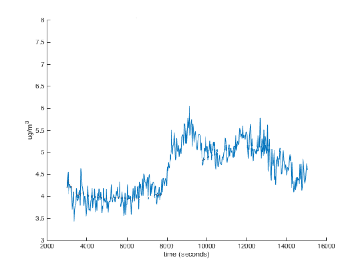
One of the easiest filters is the windowed moving average filter. This filter simply remembers the last few sensor readings (the readings in the “window”) and averages them to get the filtered value.
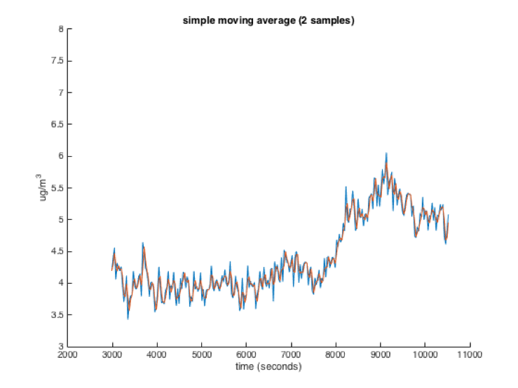
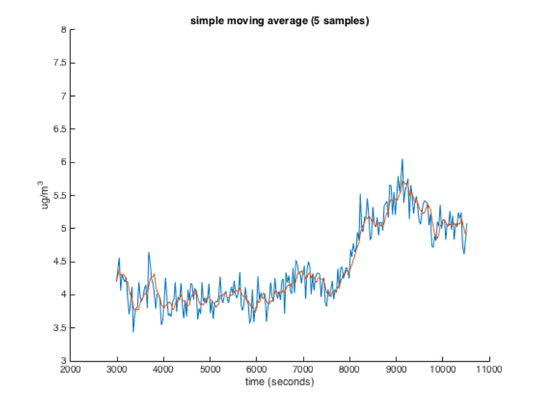
The size of the window has a large effect on how the filter performs. The larger the window, the more readings will be averaged, and thus the smoother the filtered value will be. However, a larger window will also make the filtered value respond to changes in the data slower. You can see the results of a moving average filter on a dataset in the four images below (Red is the moving average, Blue is the raw data):


An important thing to keep in mind when using windowed moving average filters is that a sensor reading only affects the average while it is in the filters window. As it leaves the window, its influence drops from 1/numSamples to 0 immediately. If that sensor reading is a very high or low outlier, your average may suddenly change when that sensor reading drops out of the window.
/*
  Smoothing

  Reads repeatedly from an analog input, calculating a running average and
  printing it to the computer. Keeps ten readings in an array and continually
  averages them.

  The circuit:
  - analog sensor (potentiometer will do) attached to analog input 0

  created 22 Apr 2007
  by David A. Mellis  <dam@mellis.org>
  modified 9 Apr 2012
  by Tom Igoe
  modified 21 Jan 2018
  by Joseph Paetz

  This example code is in the public domain.

  http://www.arduino.cc/en/Tutorial/Smoothing
*/

/*
 * Global variables in this section can be used by any function in the whole sketch
 */
// Define the number of samples to keep track of. The higher the number, the
// more the readings will be smoothed, but the slower the output will respond to
// the input. Using a constant rather than a normal variable lets us use this
// value to determine the size of the readings array.
const int NUM_READINGS = 10;

// the readings from the analog input. This is an array of type int (essentially a list of integers)
// The number of integers the array can hold is between the square brackets, in this case NUM_READINGS
int readings[NUM_READINGS];

// the index of the current reading (The location in the readings array where we will write the next reading
// (remember that the first element in an array is actually at index 0)
int readIndex = 0;
int total = 0;                  // the running total of all readings in the readings array
int average = 0;                // the average
const int SENSOR_PIN = A0;              // the sensor's pin

void setup() {
  // Setup the Serial port at a speed of 9600 baud (bits per second)
  Serial.begin(9600);

  pinMode(SENSOR_PIN, INPUT);

  // initialize all the integers in the readings array to 0, since values in an array
  // may not be 0 at the start of the sketch.
  // Since the array will be all zeros at the start of the loop, the filtered value will
  // be influenced by these zeros (and likely innacurate as a result) until we get enough
  // sensor readings to fill the array with actual values.
  for (int thisReading = 0; thisReading < NUM_READINGS; thisReading++) {
    readings[thisReading] = 0;
  }
}

void loop() {
  // subtract the last reading which is at the current readIndex, and which
  // we are about to overwrite:
  total = total - readings[readIndex];

  // read from the sensor:
  readings[readIndex] = analogRead(SENSOR_PIN);

  // add the reading to the total
  // If you have more readings, this may cause total to overflow
  total = total + readings[readIndex];

  // advance to the next position in the array:
  readIndex = readIndex + 1;

  // if we're at the end of the array (aka readIndex is too large to refer to a position in the readings array)
  if (readIndex >= NUM_READINGS) {
    // wrap around to the beginning:
    readIndex = 0;
  }

  // calculate the average
  //Since we are dividing two variables with int data types, this will truncate any decimal part of the average
  //in order to leave us with an integer result
  average = total / NUM_READINGS;

  // send it to the computer as ASCII digits
  Serial.println(average);
  delay(50);        // delay in between reads for stability
}
Exponential moving average filter
Another way to implement a moving average filter is the exponential moving average. This filter is simpler to implement, but has slightly different behavior than the windowed moving average.
The exponential moving average is kind of like the average of the new sensor reading with the previously calculated average. The exact equation is:
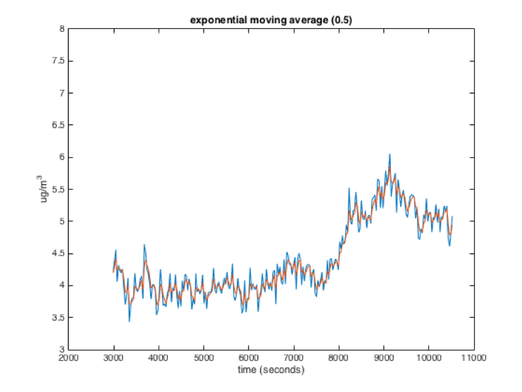
new_average = (previous_average * x) + (sensor_reading * (1 - x))
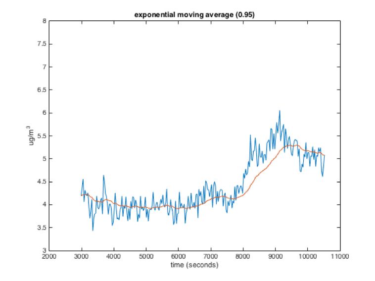
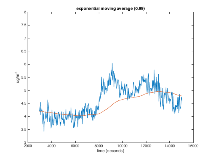
x in the equation above is a weighting factor that is usually used to weight the previous average more than the sensor reading. The following graphs show raw data (blue) and the data filtered with an exponential moving average (red). The number in parentheses at the top of each graph is the value of x for each of the filters. As you can see, a higher value for x is somewhat like a larger window for the windowed moving average. The filtered value is smoother but responds slower to changes in the data.
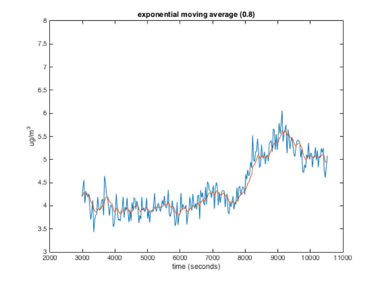
While the exponential and windowed moving averages behave similarly, they have different characteristics. Importantly, in an exponential moving average, a sensor value will theoretically influence the average forever, with its influence getting smaller each loop. This is different from the windowed moving average where the influence of a sensor reading stays constant while it is in the window and then drops to 0.
/*
 * Exponential Decay Filter
 *
 * Demonstrates how to implement an exponential decay filter.
 * In this example, analog readings from pin A0 will be filtered.
 *
 * The circuit:
 *  - analog sensor (potentiometer will do) attached to analog input 0
 *
 * Joseph Paetz 1/2018
 * released to the public domain by the author
 */

// "global" variables in this section can be used by any function in the whole sketch
float filtered_val = 0;  // this variable, of type float (decimal), holds the filtered sensor value
const float PREV_WEIGHT = 0.8; // this variable, of type float (decimal), determines the previously filtered value's weight.
const float CUR_WEIGHT = 1 - PREV_WEIGHT; // this variable, of type float (decimal), determines the current sample's weight.
const int SENSOR_PIN = A0; // this variable, of type int, determines the sensor's pin.

void setup() {
  // Setup the Serial port at a speed of 9600 baud (bits per second)
  Serial.begin(9600);

  pinMode(SENSOR_PIN, INPUT);

  // We want to initialize the filtered value with an actual reading (instead of zero)
  // so the filtered value does not need to "ramp up" from zero to the average reading.
  // We could not do this above since code can only be executed within functions.
  filtered_val = analogRead(SENSOR_PIN);

  // Print the intial value so we can see it
  Serial.print("initial filtered value: ");
  Serial.println(filtered_val);
}

void loop() {
  // This local variable of type float will store the current sensor reading.
  // We use a float because we will be multiplying it by a float later.
  float cur_reading;

  // We can convert the integer value returned by analogRead to a float by casting it
  cur_reading = (float)analogRead(SENSOR_PIN);

  // Calculate the next filtered value
  filtered_val = filtered_val * PREV_WEIGHT + cur_reading * CUR_WEIGHT;

  // Print the filtered value so we can see it
  Serial.print("filtered value: ");
  Serial.println(filtered_val);

  // Delay a little bit so we are not reading the sensor quite so fast
  delay(50);
}
One subtlety to keep in mind: you may want (or not want) to run the smoothing function at a different rate than the data acquisition happens. In the above code, each time a new data point is recorded by cur_reading = (float)analogRead(SENSOR_PIN);, the smoothing runs once: filtered_val = filtered_val * PREV_WEIGHT + cur_reading * CUR_WEIGHT;. This is because they’re both in the same functional loop, right on top of each other. But it would be possible to set the filtering function to run independently from the data acquisition, for instance by using the Blink without blocking paradigm to trigger one or the other action. If you filtered much faster than acquired data, then the filter would smooth much more, acting as if the incoming data was itself smooth (because it would keep reusing the last reported datum). On the other hand, if you let two data points in a row come in before running the filter, the older one would be totally ignored since this algorithm cares only about the most recent datum. In practice the easiest way to avoid either of these cases is to do data acquisition and filtering sequentially, as the example above does.
Frequency finder sketch
If you have a device producing a fast oscillation on a pin, you may want to have a reliable way of counting that oscillation and calculating its frequency. The “Frequency finder” sketch below uses an interrupt, a special electronic facility of the Arduino, to achieve that goal. Interrupts are especially well-suited to counting something that happens very quickly; see the comments in the code below for more information and explanation.
/*
   Frequency finder: assumes a square-wave digital signal on an input pin
   (pin 2 specifically) and computes an exponential running average of the
   frequency of the oscillation of that signal, reported in hertz.

   Because it's using the Arduino's interrupt capability, this counter is
   able to run fairly quickly, and should be able to be used for signals
   in the ~kilohertz range. (This is not tested as of this writing!)

   How it works:
   An "interrupt" pin (a pin with the ability to detect electrical changes at a
   high rate, even while other code is running) is assigned. Whenever pin 2's
   signal goes from 0V to 5V, the "Interrupt Service Routine" (ISR) is immediately
   called, which here runs a function called readPulse(). That function simply
   increments a counter. Every TIMERWAIT milliseconds (the user can change this value),
   the number of increments since the last check is calculated; the instantaneous
   frequency is simply the number of pulses divided by TIMERWAIT in seconds.

   The running average of the frequency of oscillation (in hertz) is stored in
   the variable called "averagedFreq." If the global variable "SERIALFEEDBACK" is
   declared as "true" then the value of "averagedFreq" will be reported to the
   serial monitor every "WAIT" milliseconds, which is useful for debugging. You may
   also use a different piece of software (such as Matlab, Mathematica, etc.) to read
   this value for analysis, storage, control, etc.

   by Robert Zacharias, rzachari@andrew.cmu.edu
   Carnegie Mellon University, Pittsburgh, Pennsylvania
   released to the public domain by the author, 2018
*/

// set SERIALFEEDBACK to true to return serial feedback (optional)
const bool SERIALFEEDBACK = true;

const int SERIALWAIT = 100; // milliseconds between serial prints

// milliseconds between: 1) calculating new instanteous frequency and 2) performing
// exponential smoothing operation including that new data point
const int TIMERWAIT = 100;

// This variable is used to calculate the exponential running average:
// higher OLDWEIGHT means *more* smoothing operates, and lower OLDWEIGHT means
// the newly arrived data points have more weight, i.e. *less* smoothing.
// (0 ≤ OLDWEIGHT ≤ 1)
const float OLDWEIGHT = 0.9;

// do not reassign this pin casually; it needs to be an interrupt-capable pin
const byte READPIN = 2;

// volatile data type needed for the count because its value will be affected by the ISR
volatile unsigned long count;

float averagedFreq, instantaneousFreq; // variables to store frequency data
unsigned long timer; // variable to store last time the frequency calculator ran

void setup() {

  // setup pin 2 as the input for the device
  pinMode(READPIN, INPUT);

  //  assign pin 2 as an "interrupt" pin. In this case, every time a "rising"
  //  signal is seen on pin 2 (i.e. going from 0V to 5V), the function called
  //  readPulse() will immediately run. That function is defined below the loop().
  attachInterrupt(digitalPinToInterrupt(READPIN), readPulse, RISING);

  Serial.begin(115200);
  delay(200);
}

void loop() {

  // every TIMERWAIT milliseconds, calculate new instantaneous frequency
  // and run the exponential smoothing operation with that new data
  if (millis() - timer > TIMERWAIT) {
    static unsigned long lastCount;

    // the variable "count" will be incremented by the ISR function, "readPulse()"
    unsigned long countDiff = count - lastCount;

    // convert from frequency per TIMERWAIT milliseconds to frequency per second
    instantaneousFreq = countDiff * (1000 / TIMERWAIT);

    // the exponential smoothing operation
    averagedFreq = (averagedFreq * OLDWEIGHT) + (instantaneousFreq * (1.0 - OLDWEIGHT));

    // reset counter and timer for next time this if() runs
    lastCount = count;
    timer = millis();
  }

  /*
     User can insert whatever function(s) they'd like based on averagedFreq.
     For instance:

     To calculate a flow rate through a pipe with a hall-effect flow sensor:

        float flowrate = averagedFreq * VALUE;

      where VALUE is an empirically determined constant associated with that particular
      piece of hardware.

      Or:

        if (averagedFreq > 150) {
          something that is triggered at any higher frequency than 150Hz
        }
        else if (averagedFreq > 100) {
          something that's triggered when (100Hz < averagedFreq ≤ 150Hz)
        }
        else {
          something that's triggered when (averagedFreq ≤ 100Hz)
        }

  */

  // optional serial feedback will print the averageFreq every SERIALWAIT milliseconds
  if (SERIALFEEDBACK) {
    static unsigned long lastDebugPrint = 0;
    if (millis() - lastDebugPrint > SERIALWAIT) {
      Serial.println(averagedFreq);
      lastDebugPrint = millis();
    }
  }
}

// the Interrupt Service Routine (ISR) that is called whenever pin 2 transitions 0V -> 5V
void readPulse() {
  count++;
}
MQTT sample sketch
IDeATe hosts a server which allows computers using the MQTT protocol (typically, “internet of things” devices) to communicate with each other quickly and easily through the internet. For technical information on IDeATe’s server, please see https://mqtt.ideate.cmu.edu.
Dr. Garth Zeglin, who teaches 16-223 Creative Kinetic Systems (our sister course), has written some Python programs to allow students to interface their own Arduinos with the IDeATe MQTT server. The below sketch is relevant to the “Arduino-MQTT Bridge” program (information page; direct code download).
This sketch shows an example of how you could configure an Arduino to work with the Arduino-MQTT Bridge program to:
- transmit values from a potentiometer every half second (i.e. output data to a remote site), and
- interpret incoming values to change the brightness of an LED (i.e. read input data from a remote site).
In the sketch below, the Arduino accepts incoming serial data in the range 0–99, and writes outgoing serial data in the same range. This is designed to mesh well with the Project 1 assignment, which specifies those numerical ranges for all input/output data.
/*
 * Pot and LED for MQTT
 *
 * The Arduino reads an input (in the form of a potentiometer)
 * and writes an output (in the form of an LED).
 *
 * The potentiometer's value is mapped to a 0-99 range, saved
 * into "outVal," and printed to the serial port every half second.
 *
 * Incoming serial data is saved into "inVal," assumed to be in
 * the 0-99 range, and used to drive the LED's brightness.
 *
 * This is a sample sketch meant to be used with the qt_arduino_mqtt_bridge
 * program, available at:
 * https://courses.ideate.cmu.edu/16-223/f2020/text/code/Arduino-MQTT-Bridge.html
 *
 * Robert Zacharias, rzachari@andrew.cmu.edu, Sept. 2020
 * Released to the public domain by the author
 */

const int POTPIN = A0;
const int LEDPIN = 5;

const unsigned long WAIT = 500;
unsigned long timer;

int inVal, outVal;

void setup(){
  pinMode(POTPIN, INPUT);
  pinMode(LEDPIN, OUTPUT);

  Serial.begin(115200); // qt_arduino_mqtt_bridge uses this rate
  Serial.setTimeout(50); // wait ≤ 50 milliseconds to parse incoming data
}


void loop(){
  int LEDbrightness = map(inVal, 0, 99, 0, 255);
  analogWrite(LEDPIN, LEDbrightness);

  if (millis() - timer > WAIT){
    int potRead = analogRead(POTPIN);
    outVal = map(potRead, 0, 1023, 0, 99);
    transmitSerialSignal();
    timer = millis();
  }
}

void serialEvent(){
  /*  You do *not* need to call this function in your loop;
      it is a special function that will run whenever serial
      data flows into the Arduino. */

  /*  The function assumes your machine's input value
      is called "inVal" (change that variable name as needed) */

  // if there is incoming serial data, read it
  while (Serial.available() > 0){
    // interpret incoming digits as integer and save into inVal
    inVal = Serial.parseInt();
  }
}

void transmitSerialSignal(){
  /* You should call this function 2-4 times/second in your
     main loop to transmit information to the next Arduino
     in the transmission chain. */

  /* Assumes your machine's outgoing value is called outVal
     (change that variable name as needed) */
  Serial.println(outVal);
}
Footnotes
-
That number, 32,767, is the largest value of type
intthat an Arduino Uno is able to store. If you ask the Arduino Uno to solve the seemingly simple math problem 32767 + 1, it will answer –32768; this is because you’re causing it to “roll over” from the largest-possibleintto the smallest-possible one. This Wikipedia article explains what’s going on. ↩
