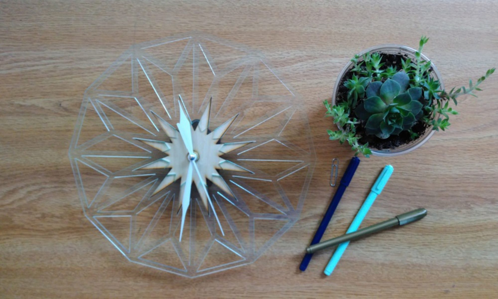
OVERVIEW
This Guide details items and workflows discussed and reviewed during class. The Guide will assist with File Preparation for Project 1, reviewing Options, Settings, and Geometry Prep.
OPTIONS
- Begin by setting the correct options. Type OPTIONS into the Command Prompt and press ENTER.Units: Begin by determining the form of measurement you would like to use. Regardless of your selection (Metric or Standard), you should select a Unit that is relative yo your project’s work size. We should be using Inches, or Millimeters.
- Grid: Set your Grid Size & Snap to something accommodating.
- Inches:
- Grid Line Count = 360
- Minor Grid Lines = 0.25
- Major Grid Lines = 4
- Snap Spacing = 0.25
- Millimeters:
- Grid Line Count = 1500
- Minor Grid Lines = 5
- Major Grid Lines = 2
- Snap Spacing = 5
- Inches:
- Snaps: Turn your Grid Snap, and Object Snap ON. The following O-Snaps should be activated:
- End
- Mid
- Cen
LAYOUT
- Simulate your workzone, by creating a RECTANGLE that resembles the size of your work area.
- RECTANGLE (in)
- First Corner = 0,0
- Other Corner = 47.2441” x 35.4331”
- RECTANGLE (mm)
- First Corner = 0,0
- Other Corner = 1200mm x 900mm
- RECTANGLE (in)
- Simulate your stock by creating a RECTANGLE that resembles the size of your Material.
- RECTANGLE (in)
- First Corner = 0,0
- Other Corner = 12” x 12”
- RECTANGLE (mm)
- First Corner = 0,0
- Other Corner = 305mm x 305mm
- RECTANGLE (in)
ARRANGE
MOVE your Workzone RECTANGLE, from its Center Point, to the Grid Origin Point. (0,0,0)
- Select your Workzone RECTANGLE, and place it on its own Layer. Re-title the Layer as ‘WORKZONE’. Lock the Layer.
- MOVE your Simulated Stock, from its Center Point to the Grid Origin.
- Select your Simulated Stock, and place it on its own Layer. Re-title the Layer as ‘Stock’. Lock the Layer.
CREATE
- Create a Large CIRCLE
- Center of Circle = 0,0
- Diameter = 8” or 205mm
- Create a Small CIRCLE
- Center of Circle = (0,3”) or (0,76.2mm)
- Diameter = 1” or 25.4mm
- Select the smaller circle, type ARRAYPOLAR into the Command Prompt
- Center = 0,0
- Number of Items = 12
- Press Enter
- SELCIRC and transfer all smaller diameter CIRCLEs to their own layer.
- Create TEXT
- Height = 1” or 25.4mm
- Value = 12
- Select your TEXT, and type MOVE into the Command Prompt
- MOVE your TEXT from Center Point
- MOVE your TEXT to the Center Point of the 12 o’clock Circle
- Duplicate your TEXT and re-number with one of the following options
- ARRAYPOLAR
- ARRAYPOLAR your existing TEXT.
- Re-number the TEXT by Double-Clicking the TEXT.
- COPY
- COPY your TEXT from Center Point to Center Point.
- Re-number the TEXT by Double-Clicking the TEXT.
- TEXT>MOVE
- Use the TEXT Command to create new TEXT.
- MOVE the new TEXT from Center Point, to Center Point.
- ARRAYPOLAR
- EXPLODE TEXT
- Type SELTEXT into the Command Prompt, then EXPLODE your TEXT
- Play
- Utilize Curve and Polyline Commands to create Cutting and Engraving Geometry for your Clock Face. Make it unique- make it your own!
- EXPORT SELECTED
- Select the Geometry for Laser Processing ONLY. Turn OFF any Layers that will not be processed. Export the Geometry as AUTOCAD [.dxf] Filetype. Choose ‘Default’ when prompted.
LASER OPERATION
- Import
- Import your file into LaserCut.
- Operation
- Adjust Vector vs Raster Settings by setting specific geometry on specific Setting LAYERS.
- Observe all Laser Policy
- Operate Laser Equipment, using proper Procedural Guidlines
