Assignment 3: Traffic Light For The Color Blind

Premise

I was driving a friend of mine that’s colored blind, and we stopped at a traffic light. I asked him, “how can you tell if it’s red or green or yellow?”

He said, “I usually guess. During the day I can see if the top or the bottom one is one, but at night it’s hard to tell, so I just wait and see if other people go, then I’ll go.”

I thought there must be another way to design traffic lights for the color blind, but for now, hope this solution helps.

Traffic Light Translator

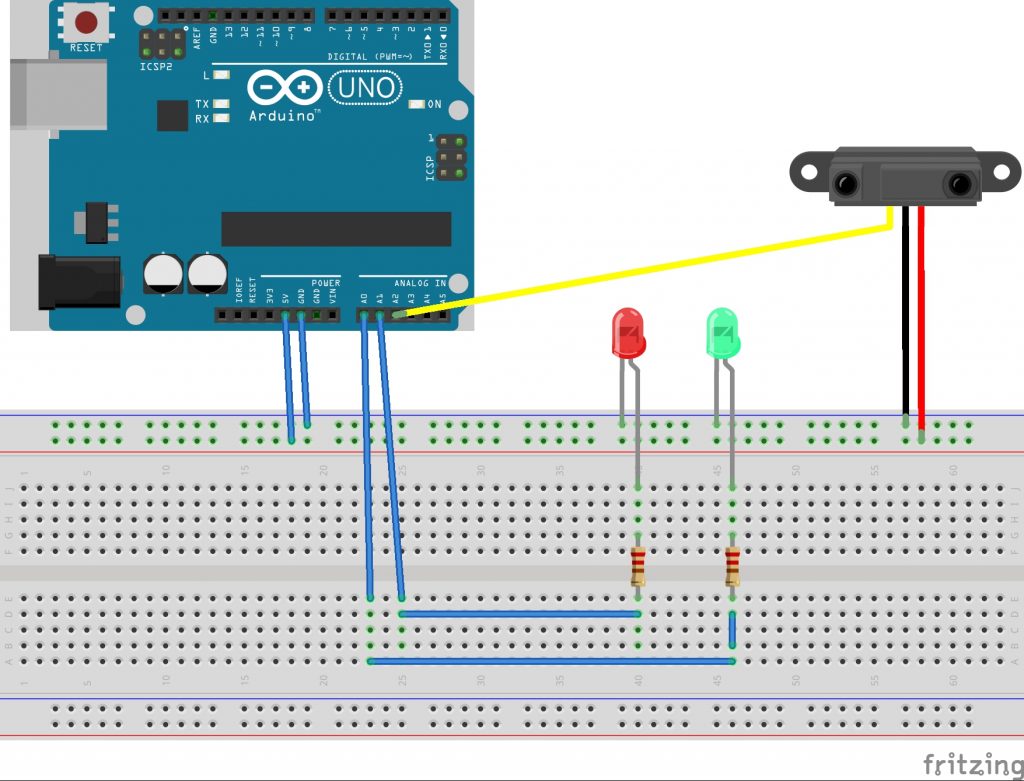
The project reads which state the LED is on (red, yellow, or green), and based on that it prints on a screen the state in which the traffic light is on. Also, at the bottom it prints a countdown in seconds to how long you have left in that state.

This could also be useful to anyone, not just color blind people. For example, if something is blocking your view to the traffic light (i.e poor weather or giant truck in front of you), this display could exist in people’s cars and show you what state the traffic light is on.

For this to be implemented, there needs to be a way for the device to know which traffic light to read the state of, which I am unsure of how to do. Possibly, using GPS coordinates?
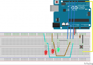
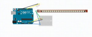
Proof of Concept

Code & Files

Alsanea_Files

Note: I did not include a schematic diagram because I used the board’s built in LED.

Visualizing Automatic Restroom Appliance States

Problem:

Automatic restroom appliances such as faucets and hand dryers are becoming increasingly popular in public and private applications alike. While this technological innovation has many befits in terms of convenience, sanitation, and energy efficiency, it is also the source of a great deal of frustration when things don’t function as intended.

All too often, I’ve found myself waving my hands vigorously underneath an automatic faucet to no avail. One of my main complaints about the interaction is that there’s no way to know which part of the state machine isn’t functioning properly. Could it be that the sensor isn’t seeing my hands because I didn’t position them properly? Is there simply a delay before water begins to dispense? Or is the sensor malfunctioning altogether?

Proposed Solution:

To solve this problem, I propose implementing a visual feedback system (using multicolored LEDs) to inform users whether any malfunction is due to their own error, or if it is a fault in the electronic system.

Proof of Concept:

I wired two different colored LEDs (green and red) to serve as a simple, intuitive, visual representation of the states of an automatic faucet. The LED s are directly linked to the infrared distance sensor that serves as an input to the system. If the green LED turns on, the sensor sees the user’s hands. If the red LED is on, the distance sensor is reading a value outside of its range, indicating that the electronic system is broken. In the case that the green LED turns on but water isn’t dispensing after a few seconds, users will know that there is malfunction in the hydraulic system.

Brief video demonstration

Assignment 3 ino

Assignment 3: Bedroom Way-finding

Problem: Bedroom floors (especially mine) are usually in constant states of disarray… but they are variable states of disarray. Sometimes I leave my backpack in the middle of the floor or pull my desk chair to the foot of my bed or any number of things. No matter the situation, everyone can relate to tripping on any number of items on the floor of your bedroom because the lights are off in the room… Can someone develop a way-finding system for rooms when the overhead lights are off to 1) avoid waking others in the room and 2) avoid stepping on/tripping over things?

Describe the general solution: In the smart house of five years from now, each floor would be equipped with pressure sensors and pinhole-sized LEDs. As someone wakes up and looks to leave their bed, they can press one button on their bedside monitor to see a softly-lighted, real-time path charted for them on their floor.  

Proof of Concept: Essentially, someone presses and holds the button on the console to turn the device on. While on, the device reads in data from the pressure sensors on the floor – wherever those sensors read in additional weight, those areas get marked as a location where an object was detected and then triggers the corresponding LED to not turn on. In effect, pressing the console’s switch illuminates (with very soft light, as to not wake up others in the room and to be easily identified by your own eyes adjusting to being awake) the locations in the room where someone can step to get to their destination. Eventually, using Machine Learning/AI techniques, the console could plot your best path to a certain destination given the time you wake up and your own tendencies (to the shower if it is 7am or to the fridge for a late night snack at 12:30am).

In this demo, I can press the momentary switch to simulate turning the whole system “on”. With the button pressed, I can apply pressure to one of the 3 round FSR’s which causes its corresponding LED to turn off, signaling that you should not walk in that position.

Assignment 3 (Sketch, Frtizing Files)

Assignment #3 – Garbage Trash Cans

Problem: At the Chick-fil-a near Waterfront, they have some trash cans.  They’re bad, they’re garbage, and they’re intended to stop users from putting in new trash while they compress down the previous user’s inputted garbage.  While this is a good idea in saving space, it’s annoying to wait for the trash can to finish compressing, and the only feedback is the audio of the trash can compressing.  There is no warning for “you cannot put trash in right now.”  There is, I think, a place for it on the top of the trash can, but its either always burnt out or never working, so here is my solution instead.

Solution: An interruptable trash can state machine that effectively warns patient users when it is busy and allows impatient users to dump their trash in and move on.

Proof of Concept: The trash can will have three added lights, one for “trash allowed” and two for “compressing, please wait.”  Additionally, users will be able to interrupt the compressing state to dump their trash in anyway, which may then lengthen the next compressing state.  This is intended to allow it to compress primarily when people are not using it.  For simplicity, the putting trash in the trash door is represented by a momentary switch.

Video: Chance Assignment #3

Fritzing Sketch:

Chance Assignment #3

Still shaking off the rust of my circuitry skills, but after this I’m pretty comfortable.

Arduino Sketch:

Assignment3_Chance files

Basic psuedo-state machine.  The RED state defaults back to the GREEN state after X amount of time, user definable.  I hope to write proper states and transitions moving forward, something I know but just didn’t have time for this assignment.

// Chance, Assignment 3.  Honestly just glad I got something working well.

#define Serial SerialUSB

const int buttonPin = 2;     // momentary button
const int greenLED =  13;    // green LED
const int redLED = 11;      // red LED
const int red2LED = 9;      // second red LED


void setup() {
  // initialize the LED pins as an outputs:
  pinMode(greenLED, OUTPUT);
  pinMode(redLED, OUTPUT);
  pinMode(red2LED, OUTPUT);
  // initialize the pushbutton pin as an input:
  pinMode(buttonPin, INPUT);
}

// state vars
int reading, previous = LOW;
int state = LOW;

// timer stuff
long time = 0;
long debounce = 200;

void loop() {
   reading = digitalRead(buttonPin);

  // check for state toggle and account for input delay
  if (reading == HIGH && previous == LOW && millis() - time > debounce) {
    if (state == HIGH)
      state = LOW;
    else
      state = HIGH;

    time = millis();
  }

  manageState();

  previous = reading;
}

// quick and easy psuedo timer thats badly CPU bound
int counter = 0;

// i didnt write a ""good"" state machine with transitionsn yet, short on time
void manageState() {
  bool tempState = sin(0.025 * millis()) > 0.0; // sloppy timer solution
  Serial.println(counter);
  switch(state) {
    case HIGH:
      counter = 0;
      digitalWrite(greenLED, HIGH);
      digitalWrite(redLED, LOW);
      digitalWrite(red2LED, LOW);
    break;
    case LOW:
      counter++;
      if(counter++ > 1000 * 20) {
        state = HIGH;
        previous = HIGH;
      }
      digitalWrite(greenLED, LOW);
      digitalWrite(redLED, tempState ? HIGH : LOW);
      digitalWrite(red2LED, tempState ? LOW : HIGH);
    break;
    default:
        digitalWrite(greenLED, LOW);
        digitalWrite(greenLED, LOW);
  }
}

Assignment 3: Visual display of a state that does not have a visually observable state

If you have any questions, please drop me email and I’ll update this post.

Assignment 3: Visual display of a state that does not have a visual state

Due: 11:59pm, Monday, 9 September, 2019

What to turn in: For now, combine your sketch files and fritzing file in to a zip file and attach that to the post describing your response.

Define a simple state machine in hardware and software representing a real system, use visual information to describe the states.  We are looking for the simplest display to provide a person with what they need to know about the state of a system.

Accessibility is a good place to start looking for a problem.  There are some accessibility issues that effect everyone, say a lack of information about an ongoing task being done by a machine.  My clothes drier has lights to tell me what it’s doing, but I have no idea how long it will be until my clothes are dry.

Example solution:

A dishwasher has three cycles: wash, rinse, and dry.  A state machine for this would have a mechanical switch that starts the state machine, timers that lead it through each state, and some visual indicator of the current state.  One solution would be LEDs representing states and a digital display showing how much time is remaining before the dishes are dry.  Would you need three LEDs for wash, rinse and dry; or would two LEDs for “washing” and “drying” be enough?  If I know it’s in “drying” mode and in a hurry I could open it up, remove an item, then dry it by hand.

Class Notes: 3 September, 2019

Visual display of information

The less types/kinds and amount of visual feedback you give the better

A clock on the classroom wall needs hours and minutes, but does it need seconds? Days?  Months?  Does your monthly wall calendar have entries for the time of day?  How about the day calendar on your desk?

Fundamental types of visual information include:

  • color
  • motion
  • intensity
  • type of display: LED, projection on a wall, display on a screenComplex types of visual state are based on the fundamental types:
  • typeface
  • language
  • icons
  • images

Visual skeuomrophism — a look that contains nonfunctional design cues.  A calendar application that looks like a paper wall calendar.

Why they are called “radio buttons”.

A soda machine that just dispensed a drink:

Icons mean different things in different cultures, does your car have email and bacon?

Physical Therapy Stretch Assist

Assignment 2: Physical Therapy Metric Assist

Problem: As someone who has dealt with a series of joint issues throughout college, I have often found it difficult to track my progress in terms of strength and flexibility. It is pretty much impossible to measure your own flexibility, especially in terms of joints like the wrist, and can be difficult to tell when you are at the right level of stretch(especially since overstretching can result in reinjury).

Solution: A wearable system that uses a series of flex sensors to see how far a joint is able to be bent in different positions. Ideally, the Arduino This would allow the user to be able to use both hands to perform stretches and exercises, and warn against any overextensions through haptic feedback through a series of dime motors, letting the user know when they are in the optimal position, and when they are overstretching.


Mockup

Device Requirements: Arduino Uno, 3.3v dime motor, flex resistor

Fritzing Sketch

Arduino Pseudocode

const int FLEX_PIN = A0; // Pin connected to voltage divider output

const int DIME_PIN = 7; // Pin connected to dime motor

// Measure the voltage at 5V and the actual resistance of your

// 47k resistor, and enter them below:

const float INPUT_VOLTAGE = 5;

const float RESISTANCE = 47500.0;


// Upload the code, then try to adjust these values to more

// accurately calculate bend degree.

const float STRAIGHT_RESISTANCE = 37300.0; // resistance when straight

const float BEND_RESISTANCE = 90000.0; // resistance at 90 deg


const float GOAL_ANGLE = 40.0; // ideal angle for bending

const float MAX_ANGLE = 55.0; // max angle for bending


void setup()

{

Serial.begin(9600);

pinMode(FLEX_PIN, INPUT);

}


void loop()

{

// Read the ADC, and calculate voltage and resistance from it

int flexCURRENT = analogRead(FLEX_PIN);

float flexVOLTAGE = flexCURRENT * INPUT_VOLTAGE / 1023.0;

float flexRESISTANCE = RESISTANCE * (INPUT_VOLTAGE / flexVOLTAGE 1.0);


// Use the calculated resistance to estimate the sensor’s

// bend angle:

float angle = map(flexRESISTANCE, STRAIGHT_RESISTANCE, BEND_RESISTANCE,

0, 90.0);

if(angle>MAX_ANGLE) {

digitalWrite(DIME_PIN, HIGH);

delay(500);

}

else if(angle>GOAL_ANGLE) {

digitalWrite(DIME_PIN, LOW);

}

Else {

}

delay(500);

}

LikeLike

https://www.facebook.com/events/1293085787539904/

Every first Friday of the month, a gallery run by a CMU professor up in Bloomfield showcases artsy / cool games.  This month, its “Analog Pleasures,” and seems super related to our class.  Per them:

A special show featuring videogames that transcend standard hardware. Have you ever played a VHS, an LED strip, or an oscilloscope? Have you ever used your sense of smell in a videogame or strapped a joystick to your crotch? This may be your only chance!

Anyway, I’ll be there if anyone else decides to come.  This post brought to you by your local ETC Students Chance and Conor.