My Dynamic Factory

This code simulates a dynamic factory environment, with variable elements including functionality of the factory, speed of the factory, the background factories, and the time of day. The idea for gears came from another class of mine in which we used squares to create interesting compositions. One of mine was created by overlaying two squares to create a “gear” so I knew I wanted to visualize it in motion for this project. I coded the gears to that they appear to work together, and appear to create an output when doing so. The rest stemmed from this “factory” theme.

painting
var angle = 0;		//gear turn
var t = 34;		//gear translate
var eSize = 10;		//ball sizes, center gear
var ballY = 409;		//front ball Y position
var recX = 7*t; 		//top piston X translation
var RecX = 7*t;			//bottom piston X tranlation 
var recY=10.5*t;		//pistons Y translation
var dir = 1; 		//top piston direction
var direction = 1;		//bottom piston direction
var speed = 2;			//piston speed
var recSize =  18;		//piston length
var BallY = 125;		//middle ball Y position
var windowSize = 25;	//window size
var Bally = 300;	//furthest ball start
var bright = 0;


function setup() {
    createCanvas(500, 409);
    background(220);
    text("p5.js vers 0.9.0 test.", 10, 15);
}

function draw() {
	background (210,146, 6);		//orange brown
	push();
	if(mouseIsPressed){
		if(mouseButton == RIGHT){		//if the right button is pressed
			background(210-mouseY/2, 146 -mouseY/2, 6- mouseY/2);		//gets darker with higher Y
				if(mouseY>height/2){		//if the mouse Y is greater half the height
			fill(255);		//stars
				ellipse (100,200,1,1);
				ellipse (200,100,5,5);
				ellipse (300,100,3,3);
				ellipse (300,200,5,5);
				ellipse (300,300,3,3);
				ellipse (150,50,5,5);
				ellipse (420,120,2,2);
				ellipse (200,100,5,5);
				ellipse (150,150,5,5);
				ellipse (180,220,2,2);
				ellipse (300,200,1.5,1.5);
				ellipse (300,250,1,1);
				ellipse (450,100,2,2);
				ellipse (100,289,5,5);
				ellipse(50,70,2.5,2.5);
				ellipse (190,120,2.4,2.4);
				ellipse (100,289,5,5);
				ellipse(50,70,2.5,2.5);
				ellipse (200,60,1.2,1.2);
				ellipse(90,90,2,2);
				ellipse (230,200,2.4,2.4);
				ellipse (460,60,5,5);
				ellipse(440,100,2.7,2.7);
				ellipse (250,250,2.4,2.4);
				ellipse (260,200,3,3);
				ellipse(240,220,2.1,2.1);
				ellipse(300,110,1.7,1.7);
				ellipse (280,190,2.3,2.3);
				ellipse (290,140,3.1,3.1);
				ellipse(215,210,2,2);
				ellipse (400,90,2.3,2.3);
				ellipse (410,120,1.5,1.5);
				ellipse(420,50,2,2);
			}
			if(mouseY<height/2){ 		//if mouse Y is lower than the height
				fill(255,255,117);
				ellipse(0,mouseY,60,60);		//sun
			}
		}
	}
pop();
push();
				fill(0,0,0,200);
rectMode(CORNER);
	var m = max(min(mouseX, 250), 0);
	var size = m * 350.0 / 400.0;
				fill(0,0,0,height-mouseY);
	rect(10,height/2-recSize*1.5,75,500);		//left chimney
	rect(0,height/2,size,500);		//left building
size = 350-size;
				fill(0,0,0,mouseY+50);
	rect(110+m*190/400,height/2-recSize*2,size,500);		//back building
		var ballWidth = max(min(mouseY, 100), 0);
	rect(110+m*190/400,height/2-recSize*4,ballWidth,37);		//back chimney
	
	if(BallY<0){		//if ball goes past 0
		BallY=height/2-recSize*4;		//reappear at height of back chimney
}

	BallY = BallY-1;	//move up by 1 point 
		ellipse(110+m*190/400+ballWidth/2,BallY,ballWidth,-ballWidth);		//middle ball

	if(Bally<0){		//if ball goes past 0
		Bally=250;		//reset ball height to 250
}

	Bally = Bally-2	;	//move up by 2 points
			fill(0,0,0,mouseX);		//opacity changes with mouseX
			if(mouseY>200){			//if mouse Y is greater than half the height
				fill(210,146, 6);		//fill changes to background (disappears)
			}

		ellipse(380,Bally,height/4 - ballWidth,height/4 - ballWidth);	//right ball
			fill(0,0,0);


rectMode(CENTER);		//rectangles oriented by center point

			fill(150);
rect(recX,recY+5,3.2*recSize,1/2*recSize);		//top piston still
rect(RecX,recY+25,3.5*recSize,1/2*recSize);		//bottom piston still

if(mouseX<1.5*t & mouseY<1.5*t){		//if mouse is in the top left corner
	if(recX>width-220 || recX

LO 03 – Computational Fabrication

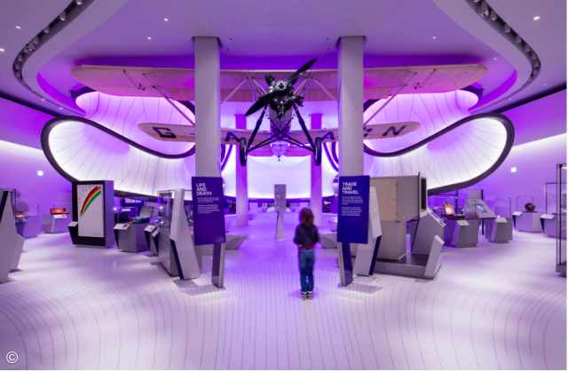
Zaha Hadid Architects created a gallery that is now displayed as The Winston Gallery in London’s Science Museum. The Handley Page aircraft is placed in the center of the artpiece while a three-dimensional pod structure curves around it. The design of the creation imitates the movement of airflow used throughout aviation industry history. I admire how the piece encapsulates the entire room and draws your eyes up towards the ceiling. I also admire the fact that the context behind this piece is deeply rooted in history and mathematics. Mathematics has allowed for the progression of the society that we know today, solving the world’s biggest problems and allowing us to advance.

The Winston Gallery (2016)

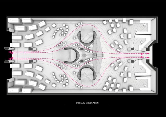
Mathemiticians and engineers used mathematical models in wind tunnels to design new aircraft. Similarly, the creators of the artpiece had the actual aircraft. They used it to construct the geometry of the gallery and the airflow that would have followed the aircraft.

The pink arrows depict the movement of air that would have flowed around this aircraft.

The creator’s artistic sensibilities manifest in the final form with a very elegant design. Dame Zaha Hadid, who was known for her use of curves, designed the smooth, curving surfaces and soft contour lines throughout the gallery.

LO – Computational Fabrication

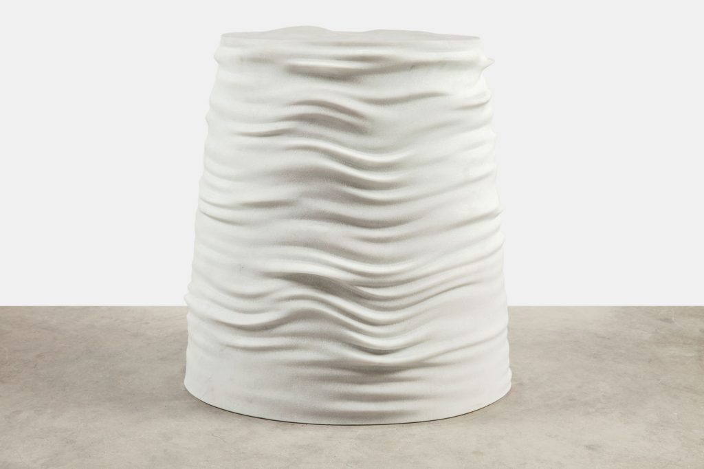
One piece of generative design that has been digitally fabricated is Brazilian architect Guto Requena’s Samba stool. It is a piece of furniture that was created based off traditional Brazilian music. The architects extracted parameters from the songs, such as the bass and treble. From that data they received frequencies that generated the curves, which grew in “real-time following the music.” The data was input into a motorized machine that is controlled by a computer, which sculpted the digital file from a cube of marble. I admire that the architects took music, which to me is a field that seemed disparate from computing, and was able to use innovations from computing to celebrate and share. The stools themselves are also beautiful! While the architect’s design sensibilities weren’t necessarily extremely prevalent, the material choice as well as the concept itself were reflective of Requena’s design personality and background.

LO 3 – Computational Fabrication

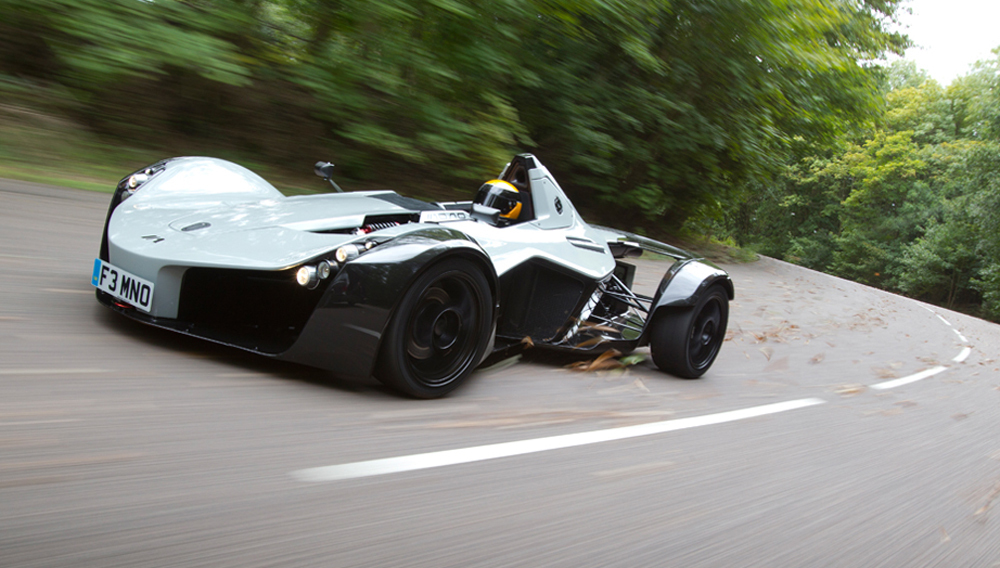
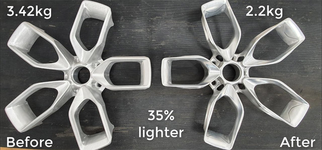
The BAC Mono is a British-built, street legal racecar designed to deliver the most pure driving experience possible. The Mono’s secret to fun lies in its weight: at only 1250 pounds, the car behaves like a scalpel, being able to turn precisely and quickly due to having little inertia.

For its 2020 refresh, BAC had to come up with creative methods to shave mass of this already featherweight machine. Partnering with Autodesk, the engineers at BAC used Fusion 360 to generate a lighter wheel. Compared to the outgoing design, this wheel saved 2.6 pounds. While this may not seem like much on paper, removing unsprung weight from the spinning wheels of a car translates tenfold towards performance. In other words, the new design actually saves about 26 pounds per wheel when the car is in motion!

To me, the majority of generative design is very obvious – the algorithms used to generate these designs have a distinct, hollowed out, weblike aesthetic. Although this is pleasing in some applications, they may not look ideal in others. In the case of the BAC Mono, maintaining the general 5 spoke design of the outgoing wheel was a priority. The end result speaks for itself – a wheel that looks virtually unchanged on the surface but is much improved underneath.

Project 03 – Dynamic Drawing

sketch
/*
 * Eric Zhao
 * ezhao2@andrew.cmu.edu
 *
 * Dynamic Drawing: This program creates an array of squares
 * and circles on the canvas. The circles light up and grow
 * in size the closer the mouse is to them, while the squares
 * rotate based on the mouse's position relative to the center
 * of the canvas. Number of circles and squares per row can be
 * changed and the program is scalable with canvas sizes.
 */


var circleDia = 0;
var mouseDist = 0;
var cursorX = 0; 
var cursorY = 0; 
var distanceMult = 0; //circle diameter multiplier
var circleCount = 15; //circle and square count
var tanRotation = 0; //square rotation state
function setup() {
    createCanvas(400, 400);
    background(220);
    text("p5.js vers 0.9.0 test.", 10, 15);
    colorMode(HSB, 360, 100, 100, 100)
    rectMode(CENTER);
}

function draw() {
    push();
    noStroke();
    circleDia = width/circleCount;
    cursorX = constrain(mouseX, 0, width);
    cursorY = constrain(mouseY, 0, height);
    //constrains mouseX and mouseY to canvas size
    background(0);
    //the following are two for loops that draw a grid of circles with
    //[circleCount] number of circles in each row and column
    for(let y = circleDia/2; y <= 1 + height-circleDia/2; y+= circleDia){
        for(let x = circleDia/2; x <= 1 + width-circleDia/2; x+= circleDia){
            mouseDist = constrain(dist(x, y, cursorX, cursorY), 1, width);
            distanceMult = mouseDist/circleCount;
            //used later to modify circle size based on mouse position
            tanRotation = atan2(cursorY - height/2, cursorX - width/2);
            //stores rotation of mouse before pushing rectangle
            push();
            translate(x, y);
            rotate(tanRotation);
            fill(15,25);
            rect(0, 0, 50, 50);
            pop();
            //draws rotated rectangles in same positions as the circle grid
            if(dist(x, y, width/2, height/2) < height/2){
            //constrains array of circles within a larger circular area
                fill(180+degrees(atan2(cursorY - height/2, cursorX - width/2)),
                65, 512/distanceMult); 
                /*adjusts HSB values based on proximity of mouse to circle and 
                coordinates of mouse relative to center of canvas*/
                circle(x, y, circleDia-distanceMult);
            }    
        }
    }
    pop();
}

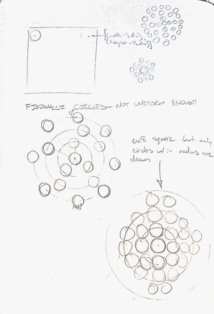
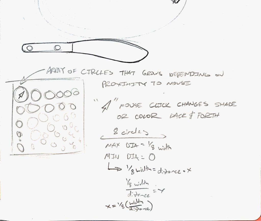
This project started with the idea of having an array of circles that grew and shrank based on how close they were to the mouse. After I made that basic program work, I started experimenting with having the mouse position change the colors of the array and using other shapes as a filter on top of the circles.

Project 3 – Dynamic Drawing

sunsetbeach
// Yoo Jin Kim
// 15104 - section D
// yoojink1@andrew.cmu.edu
// Project-03

var wavy = 10;
var toggle = 0;
var bird = 255;

function setup() {
    createCanvas(450, 600);
}

function draw() {
	//background - color changes from light blue to light purple as y-axis changes
	background(212 + mouseY / 50, 235 - mouseY / 53, 242 - mouseY / 49);

	//sun - size changes as y-axis changes 
	stroke(255);
	fill('#FFB7B2');
	ellipse(225, 418, min((mouseY), 260));

	//waves - position shift as y-axis changes 
	fill(255);
    var points = 5;
    var wav = wavy + mouseX / (width * 20);
    var step = mouseY / height * 100;

    beginShape();
    vertex(0, height);
    vertex(0, height / 1.5  + step);
    curveVertex(0, height / 1.5  + step);
    curveVertex(width / points, height / 1.5 + wav + step);
    curveVertex(2 * width / points, height / 1.5  - wav + step);
    curveVertex(3 * width / points, height / 1.5  + wav + step);
    curveVertex(4 * width / points, height / 1.5  - wav + step);
    curveVertex(5 * width / points, height / 1.5  + step);
    vertex(5 * width / points, height / 2 + step);
    vertex(width, height);
    vertex(0, height);
    vertex(0, height);
    endShape(CLOSE);

    //toggle when waves get high
    if (wav >= 15) {
    	toggle = 0;
    } else if (wav <= -15) {
    	toggle = 1;
    }

    //wave movement correction
    if (toggle == 0) {
    	wavy = wavy - 0.3;
    } else if (toggle == 1) {
    	wavy = wavy + 0.3;
    }

	//top right cloud - position shift as y-asis changes
	push();
	fill(255, 255, 255, 110);
	ellipse(440 - mouseY / 10, 320, (constrain(mouseY, 120, 320)), 25);
	pop();

	//bottom left cloud - position shift as y-axis changes
	fill(255, 255, 255, 100);
	ellipse(mouseY / 5.5, 370,(constrain(mouseY, 100, 340)), 20);

	//birds' right wings - birds move along with the mouse
	noStroke();
	fill(bird);
	arc(mouseX, mouseY, 20, 4, 0, PI + QUARTER_PI, PIE);
	arc(mouseX + 15, mouseY + 13, 20, 4, 0, PI + QUARTER_PI, PIE);
	arc(mouseX + 25, mouseY + 7, 20, 4, 0, PI + QUARTER_PI, PIE);
	arc(mouseX + 65, mouseY + 9, 20, 4, 0, PI + QUARTER_PI, PIE);
	arc(mouseX + 145, mouseY + 30, 20, 4, 0, PI + QUARTER_PI, PIE);

	//birds' left wings - birds move along with the mouse
	ellipse(mouseX - 4, mouseY - 3, 3, 10);
	ellipse(mouseX + 12, mouseY + 9, 3, 10);
	ellipse(mouseX + 22, mouseY + 3, 3, 10);
	ellipse(mouseX + 62, mouseY + 5, 3, 10);	
	ellipse(mouseX + 142, mouseY + 26, 3, 10);	

	//when the white birds go below the water, birds color changes to gray
	if (mouseY > 500) {
		bird = 205; 
	} else {
		bird = 255;
	}
}

At first, I wanted to create a realistic radial gradient sun, but the visuals did not turn out the way I expected; so I diverted direction and created a much simpler, more animated concept of the sunset beach.

LO 3 – Computational Fabrication

Norwegian Wild Reindeer Centre Pavilion (2011) by Snøhetta

The Norwegian Wild Reindeer Centre Pavilion is an observation pavilion that overlooks the Snøhetta mountain in Norway. The rock shaped wooden core represents the surrounding rock that has been eroded due to wind and running water.

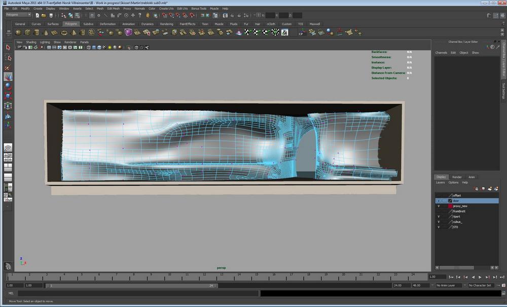
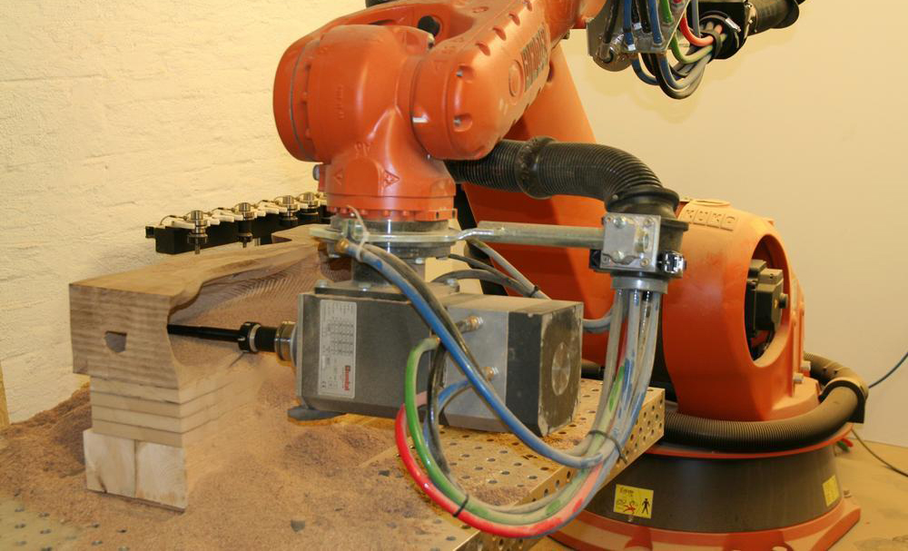
In order to generate the form, Snøhetta design team used “digital 3D-models such as MAYA to drive the milling machines, Norwegian shipbuilders in Hardangerfjord created the organic shape from 10 inch square pine timber beams.” After, the wood was assembled in a traditional way – using wood pegs as fasteners. The form resembles Snøhetta’s style of expressionism and visual boldness. Materials include pine tar treated exterior wall and oiled interior wood walls.

The pavilion is a robust yet undisturbed in its form that the building itself “gives visitors an opportunity to reflect and contemplate this vast and rich landscape.” Personally, this aesthetic and design quality is the most admirable in which this company engages the audience with the architecture as well as the landscape in a natural, flowing way.

LO: Computational Fabrication

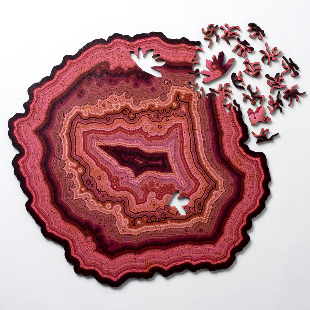
Agate Puzzle by Nervous System

One project that particularly stands out to me is the generative jigsaw puzzles by Nervous System, a Massachusetts-based design studio. They write specialized programs that imitate processes found in nature. They then use that code to create projects inspired by organic forms. Their recent geode jigsaw puzzle is made out of slices of agate that mimics the natural variations in how geodes form that changes the puzzle’s shape, color, and pattern, making each one uniquely different. The goal of Nervous System was to forge together the artistry of traditional, hand-made jigsaw puzzles with the possibilities of new technology. It is interesting using man-made technology to imitate nature and try to artificially create nature. However, by doing so, it allows us to recognize and closely analyze on how nature works. This could allow us to make advances to technology and create new opportunities that weren’t possible before.

Nervous System: https://n-e-r-v-o-u-s.com/index.php

Looking Outwards – Jason Salavon

By Eamonn Burke

I found myself fascinated and inexplicably compelled to Jason Salavon’s Glassware Still Life. What initially grabbed my attention was how tangible the glass appeared with only manipulated light, and how texturally satisfying it seems. His artistic sensibility certainly came in for this, as well as so elegantly showing how the glasses morph into one another, and create recognizable intermediary glass designs in the process. 

On a deeper level, Salavon’s piece attracted me because it’s relatable – unlike many other generative pieces that depict complex and unfamiliar  systems. This piece shows how simple objects in our lives are simply variations of one another following a generative “code”. I admire that he was able to dissect one of these everyday systems and show it so clearly. 

I know that Salavon used custom software, but I would guess that the basic code involves stretching of parameters bounded by “if ” statements. These dictate when a glass stretches (ex. Height=height+1, If height=x -> width =width+1), by how much, and in what direction, while holding certain other dimensions constant. Again, his sensibility comes in knowing when to change which parameters to create interesting intermediary designs. 

Looking Outwards-03

Work: Times Eureka Pavilion
By: NEX Architecture x Marcus Barnett

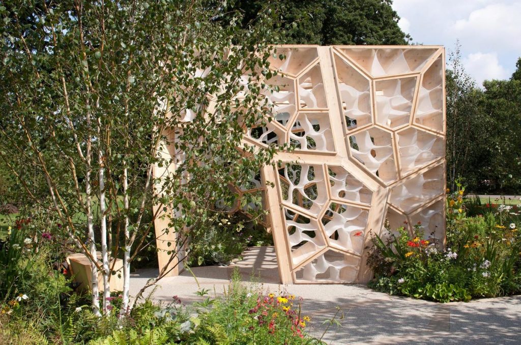
The Times Eureka Pavilion in London is the stunning result of a collaboration between NEX Architecture and Marcus Barnett for the 2011 Chelsea Flower Show. As it sits in a garden among a lush collection of plants, the pavilion imitates the cellular makeup of these plants: branch-like structures emerge from one another and let light through into the cubic space inside, as if viewers are peering through a microscope at a section of a fibrous stem. To generate this work, the creators used computational genetic algorithms, representing the intricacies of the natural world in a grander, more calculated way. I especially admire the fact that this structure gives back to the space within which it resides–it is said that the roof collects rainwater and lets it back into the soils, and the way the walls are structured disperses natural light both into the interior and exterior. I believe that this is a perfect example of technology and nature living in harmony, complementing one another instead of competing for dominance.

The Times Eureka Pavilion in London