Settings
Procedure
1. SAFETY: Make note of the nearest fire extinguisher.
2. POWER-ON: The Rabbit Laser’s rotary Power Switch (w/ key) should be switched to ON position. Leave this switch in the ON Position unless notified otherwise. If the Equipment Control Panel does not light-up, ensure the red Emergency Stop button is not activated. Twist the E-Stop to make sure it’s released.
3. HOME: Find and press the X-Y 0 Button. The lens assembly will travel to the top-right corner of the Laser bed.
4. PREP: During the HOME procedure, prepare your file in LaserCut. Download the file to the Laser Equipment.
5. MATERIAL PREPARATION: If necessary, remove protective layer from the top-side. If your material has a minimal ‘bow’ or ‘warp’, use Painters or Masking Tape to secure it to the Table as best as possible. *As indicated in Policy, do not attempt to laser excessively warped, non-planar materials.
6. MATERIAL PLACEMENT: Open the lid, make sure to minimize heavy collisions with the Laser Lens Assembly, and Vector Table. Place your material on the table. Make sure your Material is square with the table. *Recommendation: Laser power diminishes toward the front and right side of the table. Laser power is more reliable toward the rear and left side of the table.
7. MOVE XY: PRESS and HOLD the X & Y arrow keys to guide the Laser Lens assembly to ANY location above your material. IF the arrow keys do not work, find and press the ESC key, and retry.
8. MOVE Z-AXIS: From the Equipment Control Panel, lower the Vector Table by pressing and holding the ‘Z-Down‘ Arrow Button, located immediately above the ‘Z-0‘ Button.
9. SET Z-HEIGHT: Find and select the ‘Z0‘ button from the Control Panel. The equipment will adjust the table to the correct Z-Height after touching the top of your material.
10. TEST: Press the TEST button to have the laser outline the area it will cut. If the lens assembly travels off your material, adjust your home position with the X & Y arrow buttons (or just move and re-square the material by hand) and TEST again.
11. SWITCHES: Make sure all (3) Push Buttons, along the top of the Control Panel, are depressed.
3.1 The red ‘Lighting’ Button controls internal Equipment Light.
3.2 The green ‘Laser Power’ Button controls power to the Laser Tube.
3.3 The green ‘Socket Switch’ button controls power to the Water Chiller, Air Pump, Filtration System and Fan Booster.
12. START: Close the lid slowly. Find and Press the green ‘Start‘ Button, to begin your Job.
X. PAUSE: Press the green ‘Start‘ Button to Pause your Job. Make sure the lid is closed, and press the green ‘Start‘ Button again, to resume your Job.
X. STOP: Press the red ‘Stop‘ Button to Abort the Job entirely. The Laser Lens assembly will return to its original starting location.
X. EMERGENCY STOP: Find the red ‘Emergency Stop‘ Button, and press it DOWNWARD. Complete any necessary Emergency Procedures required.
13. COMPLETION: When the equipment beeps, your file is complete. Leave the Equipment Lid closed for 15 seconds to allow proper extraction of hazardous fumes. Before removing your material, make sure your parts have been cut through completely. Remove your parts and pieces. Vacuum small debris from the table and Equipment. Place un-usable scrap in the TRASH; place usable scraps in scrap storage.
14. POWER-OFF: Turn OFF the (3) Push Buttons located above the Control Panel. Leave the Rotary Power Switch (w/ key) in the ON position.
Policy
1. ACCESSIBILITY: Students are approved to use equipment, after attending an IDeATe Certified Course and/or Training Session. Approved Users must abide by Reservation, Facility & Equipment Policy and Procedure to ensure a safe, and successful working environment.
2. SAFETY: Improper Equipment use, posing a threat to the User, or others; will be grounds for Equipment and/or Facility Suspension. Users must remain AWAKE and ATTENTIVE in Laser Lab during Equipment Use and Reservation Time. Make sure you are aware of the nearest Fire Extinguisher Location.
3. PROCEDURE: The Laser Equipment involves several Procedural Steps that should be completed before, and after all operations. Equipment damages, due to improper completion or in-completion of indicated Equipment Procedure; will result in a Fine, and Suspension from the Facilities.
4. MAINTENANCE: You are required to clean up any leftover tape, dust, debris and scrap left in the Laser Lab. Plan on 5-10 minutes to complete all clean-up tasks at the end of each job. If the room and/or equipment is not sufficiently cleaned, the User is subject to a Cleaning Fee.
5. FASTENING: Material that does not sit PLANAR/LEVEL within the Laser Equipment, due to non-planar surfaces, warping or bowing; will be removed from the Work-Area and disallowed from Laser Output. Common problematic materials typically include Plywood: CDX Grade, Low Grade Birch, OSB, Carboard, Chipboard etc. Materials that have minimal warping, that can be corrected with Masking Tape- are allowable. All other Fastening Methods are considered unacceptable: Duct-Tape, Double-Sided Tape etc.
6. MATERIALS: Certain Materials cannot be processed on the Laser Equipment. These materials include; but are not limited to: Glass Mirrors (see Staff for mirrored Acrylics), Metals, Lexan Plastics, Foam Core, P.E.T.G., Styrene, PVC or PVC Based materials (Any materials containing Chlorine). Fabric Materials MUST be cut to size before Laser Cutting. (Max = 47″x35″) Materials greater than or equal to 3/8″ (9.5mm) in thickness are unacceptable. If you have a question about any material that you would like to cut, please ASK!
LaserCut
OVERVIEW
LaserCut provides a Universal Platform in which Users may import CAD Geometry, and prepare the File for Laser Processing. Users must have experience with any CAD Platform (or a Vector Based Graphics Program, i.e. Adobe Illustrator, CorelDraw etc.), to successfully operate within the LaserCut Software Environment. Users should also have completed Fire Extinguisher Training, and Policy/Procedure Training to successfully operate the Laser Equipment.
LASERCUT
![]() Find the LaserCut Application Icon on the Computer Desktop, and open the Application.
Find the LaserCut Application Icon on the Computer Desktop, and open the Application.
FILE > IMPORT
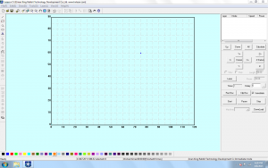
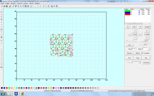
The LaserCut Interface, features various Drop-Down Menus from the Top of the screen; Command-Icon Buttons along the top and left side; a color-bar along the bottom, and Equipment Control/Layer Manager on the right side. The majority of the interface is a window, with a grid-layout. This is a TOP View of the Laser Equipment Cutting Table.
Begin, by importing a previously prepared CAD File. Adobe Illustrator (.ai) and AutoCad Drawing Exchange (.dxf) File Formats will work best for Laser CUTTING/SCORING/ENGRAVING; whereas Image formats (i.e. [.jpeg]) will work only for ENGRAVING. To import a file, browse to the ‘FILE’ Menu, and find the ‘IMPORT’ Option. Find and select your file location from the Import Window.
TOOLS > UNITE LINES
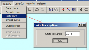
Your CAD Geometry, will be placed on the Grid. All Geometry should appear as the same color. During the import, all Joined Curve Geometry is separated/exploded into single segments- separated by their Start and End Points. Fix this issue, by selecting ALL of your Geometry (CTRL+A), then, find the ‘TOOLS’ Drop-Down Menu, and select ‘UNITE LINES’ from the list of options. A new window will appear, prompting your input for a Tolerance Value- the default setting is sufficient, Select ‘OK’ and your Geometry will be re-joined. This will create a more efficient Laser process.
BACK TO TOP
LAYERS
 Within the LaserCut Application, a User can control the order in which Geometry is Processed; and the Mode in which Geometry is Processed. To control any of these parameters, your geometry must be separated onto Layers. Your Layer Menu is located in the top-right of the LaserCut Interface. To place geometry on a Layer, or Create a New Layer, select ALL Geometry you would like to separate onto an individual Layer; then, Select a Color that suits your taste from the Color Bar at the bottom of the LaserCut Interface. Within your Layer Menu, you will find the new color listed under the Layer Column.
LAYERS > CUT ORDER
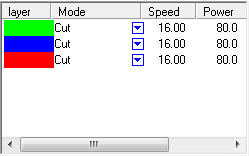
To control Cut Order, simply select a Layer, and drag it downward or upward in the Layer Menu. The Topmost Layer will cut first, and the Laser Equipment will continue to process geometry from the topmost layer- down. Cut Order, may or may not be important- depending on your File, Geometry, and Material. It is common practice, however, to cut out smaller areas first, and larger areas second. Certain Materials can bend or warp when heat is applied, so it may be necessary to cut internal structures before cutting outer/surrounding/external geometry.
The image above, indicates that all Geometry appearing in GREEN, will be processed first. BLUE Geometry, will be second- and RED Geometry will process last in the Cut Order. Note, that smaller internal geometry is cut first, and external surrounding geometry is cut last.
LAYERS > CUT MODE
Laser Modes, indicate how the Geometry should be processed. If you select the arrow, within any of your Layer’s Mode Columns, it will create a drop-down menu; allowing you to change how Geometry on each layer is processed:
‘CUT’ Mode, indicates that your geometry will be processed as Cut Lines, this Mode is most often used- and will cut through your material completely, as long as you’ve indicated the correct settings for Speed and Power.
‘ENGRAVE’ Mode, indicates that your geometry will be processed as Engraving Areas. To Engrave, you must have completely closed geometry (i.e. the Curve Start Point, and End Point exist in the same location) Alternately, you can import an image, and process as an Engraving File.
‘GRADE ENGRAVE’, indicates that your geometry will be processed as Gradated Engraving Areas. This is similar to ENGRAVE Mode, but different in that the engraving will adjust from a lighter engraving power near the edge areas, and a deeper engraving power near the center of you Engrave Areas. To Engrave, you must have completely closed geometry (i.e. the Curve Start Point, and End Point exist in the same location) Alternately, you can import an image, and process as an Engraving File.
‘HOLES’ Mode, is specifically for Circle Geometry, and useful for precise operations and parts. This Mode will control the Start and End Point Power for Circle Geometry, reducing fire hazards, and providing the User with less warping.
In the image above, ALL of our Geometry is listed as ‘CUT’ Mode. All Geometry will be cut completely through, in the order of the Layer List.
MODE SETTINGS
Each Mode, requires User Input settings, that will typically control Laser Speed, and Power. These settings, are dependent on Material Selection, Material Thickness, and the Laser Processing Mode. Users are responsible for knowing these values. It is difficult to remember every setting, for each combination of Material, Thickness, and Mode, so we’ve created a web-based form, that will assist you with these settings. Visit the [RABBIT] Laser Settings Page, and fill out the necessary information in the form-fields. Select the search button, and a new window will appear, with various tested-and-approved settings for your specific Laser Operation. To change your Mode’s Settings, Double-Click on the Layer you wish to edit, and a new window will appear with various parameters. Take the information from the [RABBIT] Laser Settings Results Page, and input them accordingly into the available fields.
Frequently, you may have a material that IDeATe@Hunt has yet to record settings for. In the event you cannot find settings for your operation/material- you may have to do some testing before-hand. Figuring out the correct settings, may take some time- but once you’ve figured them out, providing the information to an IDeATe@Hunt Staff Member, will ensure the successful future operation of similar Laser Processes. While testing, it is important that you recognize how SPEED and POWER can affect your outcome:
SPEED: Too much speed, won’t allow the Laser to pass through your Material. Faster Speeds (50%-100%), are useful for thinner and/or less dense materials- such as cardboard, matte board, illustration board, or paper. Slower speeds (1%-49%), are useful for thicker and/or dense materials- such as acrylic, MDF, and Plywood.
POWER: Too much Power, will cause a fire-hazard, and possible warping of your material. Higher Power (50%-100%), is useful for thicker and/or dense materials- such as acrylic, MDF, and Plywood. Lower Power (1%-49%), is useful for thinner and/or less dense materials- such as cardboard, matte board, illustration board, or paper.
You must find a safe, starting combination of these two values, before performing any test cuts. When in doubt, always use a lower power- this will eliminate additional, unnecessary fire-hazards. For instance, we could begin testing CUT settings for 1/8″ (3mm) thick Cardboard. If we use 50% Speed, and 100% Power, it will certainly CUT all the way through. However, the Power Setting is TOO HIGH for this material. Instead, start with 50% Speed, and 40% Power- if it doesn’t cut through, lower your Speed by 5%, and raise the Power 5%. Repeat this process until you’ve found reliable and consistent settings.
DOWNLOAD
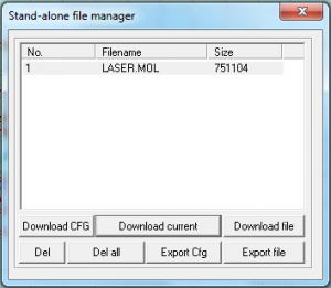
After you’ve imported your file, completed the UNITE LINES Command, organized your geometry onto layers, adjusted your Cut Order + Cut Mode, and input Laser Mode Settings- you must DOWNLOAD your file to the Laser Equipment. In the Equipment Control/Layer Menu, on the right-side of your LaserCut Interface; you will find a button near the bottom, labeled : ‘DownLoad’ Find and Select this button- and a new window will appear. This window will list any files that are currently downloaded and stored on the Equipment’s Flash Memory. Begin, by selecting the ‘Del all’ Button, to clear all existing files from the Equipment’s Memory. Next, find and select the ‘Download current’ Button, to download your current file into the Equipment’s Memory. Your file will be sent to the Laser Equipment, and you may begin Equipment and Material Preparation.
EQUIPMENT PREPARATION
Your file has been downloaded into the Equipment’s Memory, and it is ready to be processed- however, there is a specific set of tasks that must be completed before your file may be processed. Follow the Equipment’s Procedural Steps before beginning your Laser Job.
File Prep
OVERVIEW
This Guide details items and workflows discussed and reviewed during class. The Guide will assist with File Preparation for Project 1, reviewing Options, Settings, and Geometry Prep.
OPTIONS
- Begin by setting the correct options. Type OPTIONS into the Command Prompt and press ENTER.Units: Begin by determining the form of measurement you would like to use. Regardless of your selection (Metric or Standard), you should select a Unit that is relative yo your project’s work size. We should be using Inches, or Millimeters.
- Grid: Set your Grid Size & Snap to something accommodating.
- Inches:
- Grid Line Count = 360
- Minor Grid Lines = 0.25
- Major Grid Lines = 4
- Snap Spacing = 0.25
- Millimeters:
- Grid Line Count = 1500
- Minor Grid Lines = 5
- Major Grid Lines = 2
- Snap Spacing = 5
- Inches:
- Snaps: Turn your Grid Snap, and Object Snap ON. The following O-Snaps should be activated:
- End
- Mid
- Cen
LAYOUT
- Simulate your workzone, by creating a RECTANGLE that resembles the size of your work area.
- RECTANGLE (in)
- First Corner = 0,0
- Other Corner = 47.2441” x 35.4331”
- RECTANGLE (mm)
- First Corner = 0,0
- Other Corner = 1200mm x 900mm
- RECTANGLE (in)
- Simulate your stock by creating a RECTANGLE that resembles the size of your Material.
- RECTANGLE (in)
- First Corner = 0,0
- Other Corner = 12” x 12”
- RECTANGLE (mm)
- First Corner = 0,0
- Other Corner = 305mm x 305mm
- RECTANGLE (in)
ARRANGE
MOVE your Workzone RECTANGLE, from its Center Point, to the Grid Origin Point. (0,0,0)
- Select your Workzone RECTANGLE, and place it on its own Layer. Re-title the Layer as ‘WORKZONE’. Lock the Layer.
- MOVE your Simulated Stock, from its Center Point to the Grid Origin.
- Select your Simulated Stock, and place it on its own Layer. Re-title the Layer as ‘Stock’. Lock the Layer.
CREATE
- Create a Large CIRCLE
- Center of Circle = 0,0
- Diameter = 8” or 205mm
- Create a Small CIRCLE
- Center of Circle = (0,3”) or (0,76.2mm)
- Diameter = 1” or 25.4mm
- Select the smaller circle, type ARRAYPOLAR into the Command Prompt
- Center = 0,0
- Number of Items = 12
- Press Enter
- SELCIRC and transfer all smaller diameter CIRCLEs to their own layer.
- Create TEXT
- Height = 1” or 25.4mm
- Value = 12
- Select your TEXT, and type MOVE into the Command Prompt
- MOVE your TEXT from Center Point
- MOVE your TEXT to the Center Point of the 12 o’clock Circle
- Duplicate your TEXT and re-number with one of the following options
- ARRAYPOLAR
- ARRAYPOLAR your existing TEXT.
- Re-number the TEXT by Double-Clicking the TEXT.
- COPY
- COPY your TEXT from Center Point to Center Point.
- Re-number the TEXT by Double-Clicking the TEXT.
- TEXT>MOVE
- Use the TEXT Command to create new TEXT.
- MOVE the new TEXT from Center Point, to Center Point.
- ARRAYPOLAR
- EXPLODE TEXT
- Type SELTEXT into the Command Prompt, then EXPLODE your TEXT
- Play
- Utilize Curve and Polyline Commands to create Cutting and Engraving Geometry for your Clock Face. Make it unique- make it your own!
- EXPORT SELECTED
- Select the Geometry for Laser Processing ONLY. Turn OFF any Layers that will not be processed. Export the Geometry as AUTOCAD [.dxf] Filetype. Choose ‘Default’ when prompted.
LASER OPERATION
- Import
- Import your file into LaserCut.
- Operation
- Adjust Vector vs Raster Settings by setting specific geometry on specific Setting LAYERS.
- Observe all Laser Policy
- Operate Laser Equipment, using proper Procedural Guidlines
Project1
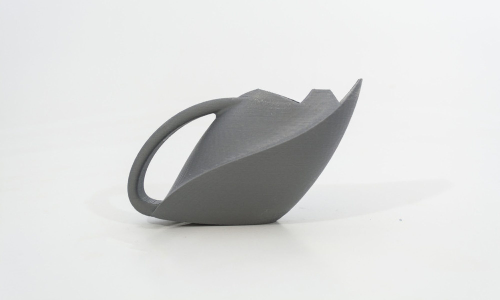
OBJECTIVE
Provide a physical item that illustrates your ability to develop a 2D Geometry file, prepare the CAD file in secondary laser application, and utilize laser cutting, engraving and scoring techniques.
CRITERIA
- Prepare a CAD File that utilizes application options, 2D Curve/Polyline geometry, layers & editing tools within Rhinoceros 3D
- Geometry must be prepared for laser cutting, engraving and scoring processes
- Successfully export from Rhino as [.dxf] file-type, and import into LaserCut
- Properly prepare LaserCut file settings/preferences
- Exhibit understanding of Equipment Policy & Procedure
- Participate in Fire Extinguisher Identification and Use Training, provided by Environmental Health & Safety
- Provide documentation of your work (Rhino File, LaserCut File, Images)
SUGGESTED PROJECT
*READ ME* The following is a suggested project. You are NOT required to follow these guidelines. You may create your own original project if you prefer:
Using a Clock Kit, and Acrylic Sheet- utilize Laser Cutting, Engraving and Scoring Techniques to create a functional Clock. This Project should illustrate the User’s ability to properly prepare a CAD File within Rhinoceros 3D for Laser Processing.
TOOLS
SUGGESTED MaTERIALS
- (1) 12″ x 12″ x 1/8″ (305mm x 305mm x 3mm) Acrylic Sheet
- (1) Clock Kit
RESOURCES
- Project Submission Guidlines
- Rhino Introductory Tutorials
- File Prep Instructions (for suggested clock project)
- Rabbit Laser Policy
- Rabbit Laser Procedure
- Rabbit Laser Settings
STEPS
1
Step 1
1. Begin by determining your Tools, Application Environments and Materials :
i. Tools: Rabbit Laser System
a. Power: 80 Watt
b. Bed Size: 1200mm x 900mm (47.25in x 36.43in)
ii. Applications: Rhinoceros 3D, LaserCut
iii. Materials: Available for purchase from IDeATe Lending (A29)
a. Suggested: Acrylic Sheet : 12″ x 12″ x 1/8″ (305mm x 305mm x 3mm)
b. For Suggested Clock Project: 12″ x 12″ x 1/8″ (305mm x 305mm x 3mm) & Clock Kit
2
STEP 2
2. Prepare your CAD File
i. 2D Geometry: Begin drawing and outlining your CAD file with Curve/Polyline creation and editing commands. Rhinoceros 3D Tutorials, Rhino File Prep for Clock Kit
ii. Organization & planning: Create Layers, and label them as ‘CUTTING’; ‘SCORING’ & ‘ENGRAVING’. Make the layer geometry identifiable by changing the layer color. Transfer geometry to these layers as necessary, to keep your file organized and understandable.
3
STEP 3
3. Export your CAD File
i. SELECT the geometry you would like to export. (DO NOT USE ‘Save as..’)
ii. Go to the FILE drop-down menu, and select the EXPORT SELECTED option.
iii. Export your file (preferably to a USB Flash Drive) as an AutoCAD [.dxf] file format.
4
STEP 4
4. Import, prepare, & send your file: LaserCut Tutorial
i. Find an open/available Laser System- using the computer, transfer your AutoCAD [.dxf] file to the desktop.
ii. Open the LaserCut Application.
iii. IMPORT your AutoCAD [.dxf] file into LaserCut. (use IMPORT, not OPEN)
iv. Unite Lines, and begin setting your preferences for each grouping/layer.
v. Download the file to the Laser Equipment.
5
STEP 5
5. Complete the process *see note 5
i. Prepare your material for Laser processing.
ii. Properly set the Z-Axis, and power ON the Lighting, Laser Power, and Socket Switch buttons.
iii. Close Lid, and use TEST to draw outline of Laser file.
a. IF all is aligned properly: Close lid and push START
b. IF TEST outline goes over your Material boundaries, adjust settings and/or file, re-download, and re-TEST.
*Note 5: The following should be completed and exercised to achieve & retain access to IDeATe Laser Equipment:
1. User must review and follow Laser Equipment Policy
2. User must review and follow Laser Equipment Procedure
3. User must participate and complete Environmental Health & Safety’s Fire Extinguisher Identification and Use Training
i. Fire Extinguisher Identification Training is offered in-class
ii. If you missed class on this day, you should schedule/reserve a spot in the next offering.
6
STEP 6
6. Submission/Documentation/Review: Guidlines
i. Provide (5) Semi-Professional Photographs of your work.
ii. Submit all relevant files:
a. Rhino File [.3DM]
c. LaserCut File [.EPS]