Tool Library

Info

What is a Tool Library?

The PHYSICAL TOOL LIBRARY is a collection of milling tools, prepared for use with a CNC Spindle that has automatic tool changing capabilities. The milling tools are loaded into a collet assembly and their locations are recorded/programmed for CNC operations.


A DIGITAL TOOL LIBRARY is a digital representation of the PHYSICAL TOOL LIBRARY. This digital reference provides details on the actual/physical tools, including important information such as the tool’s diameter, length & location. This simulated library is used in the CAM interface for collision and/or problem detection; also used for Post Processing when sending a file to the CNC Equipment (indicates tool location).

Download

Tool Libaries

The Tool Library is available for download by selecting one of the following links. *The libraries provided are for IDeATe Equipment ONLY!

IDeATe Tool Library : Standard, Inches

IDeATe Tool Library : Metric, Millimeters

Instructions

1. Tool Library: Download
Download & save the Tool Library. Make note of where the file is saved.
2. Tool Library: Browser

RhinoCAM includes (2) browser windows:

1. Machining Operations Browser (AKA MOps or Machinining Browser) Create, manage and setup machining operations and preferences.

2. Machining Objects Browser (AKA MObs) Create, organize or manage Tool Libraries, Machinine Features/Drive Geometry and template operations.

3. Tool Library: Unload/Load

Unloading an existing Tool Library or Loading a new version, can be achieved through the Machining Objects Browser.

1. OPEN the Machining Objects Browser (MObs) by selecting the TOOLS, MACHINING OBJECTS button from the Machining Operations Browser (MOps).

2. UNLOAD any existing tool libraries, if they exist- by selecting the  UNLOAD TOOL LIBRARY button.

3. LOAD a tool library by selecting the LOAD TOOL LIBRARY button; browse to the location of the tool library and select OPEN.

After loading a tool library, a list of tools should appear in the Machining Objects Browser (MObs)- as shown in the image on the right.

NVCloud: Submission & Review

After adjusting your Print Settings, you should submit your file, then review relevant print job details. After which, IDeATe Technical Staff will review your file and follow-up accordingly!

Submission

After adjusting your Print Settings, submit your file by following these steps:
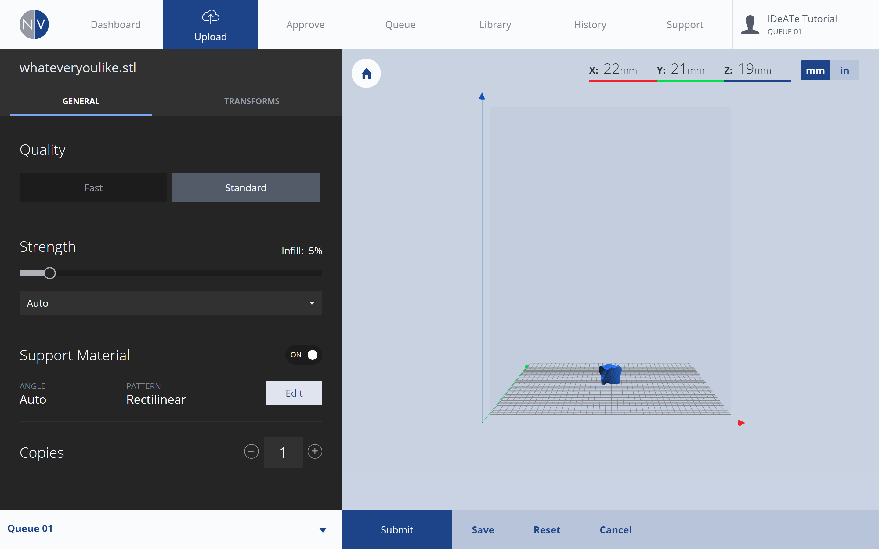

1. Copies
The COPIES setting is available from the Print Settings: General menu. COPIES affects the number of copies to be printed. If you plan on printing more than (1), adjust your desired quantity here.
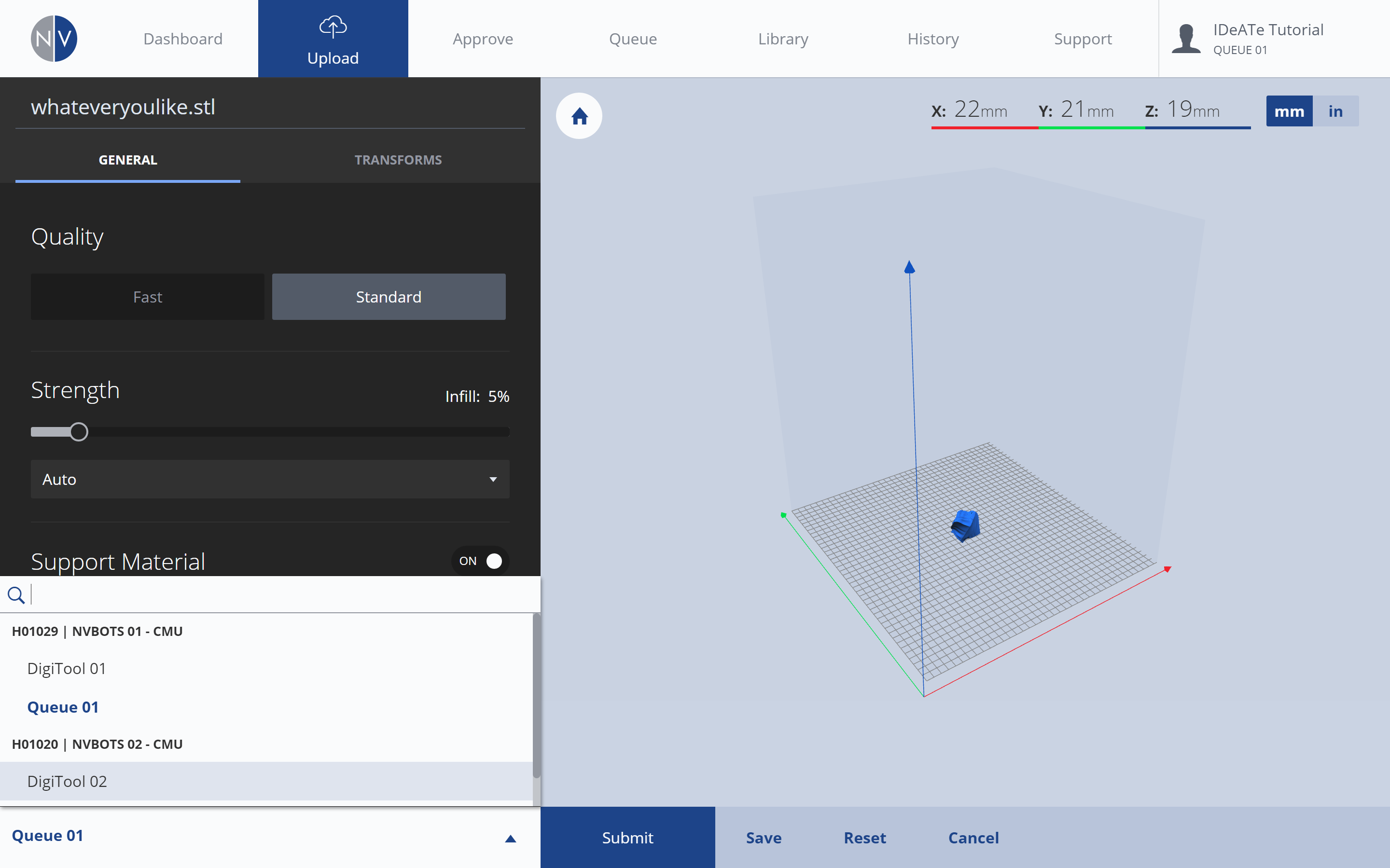
 

2. Group
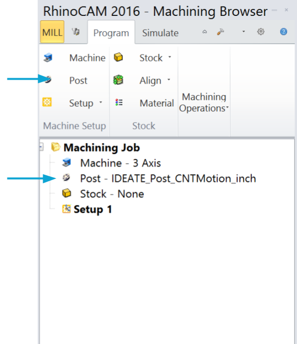
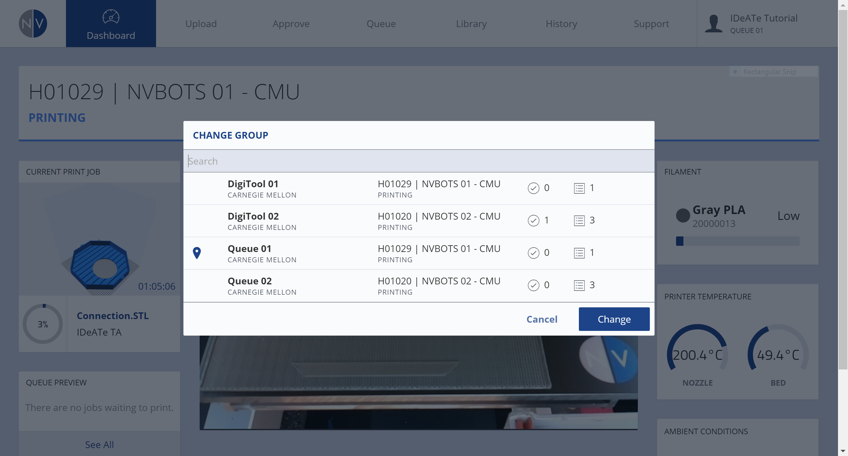
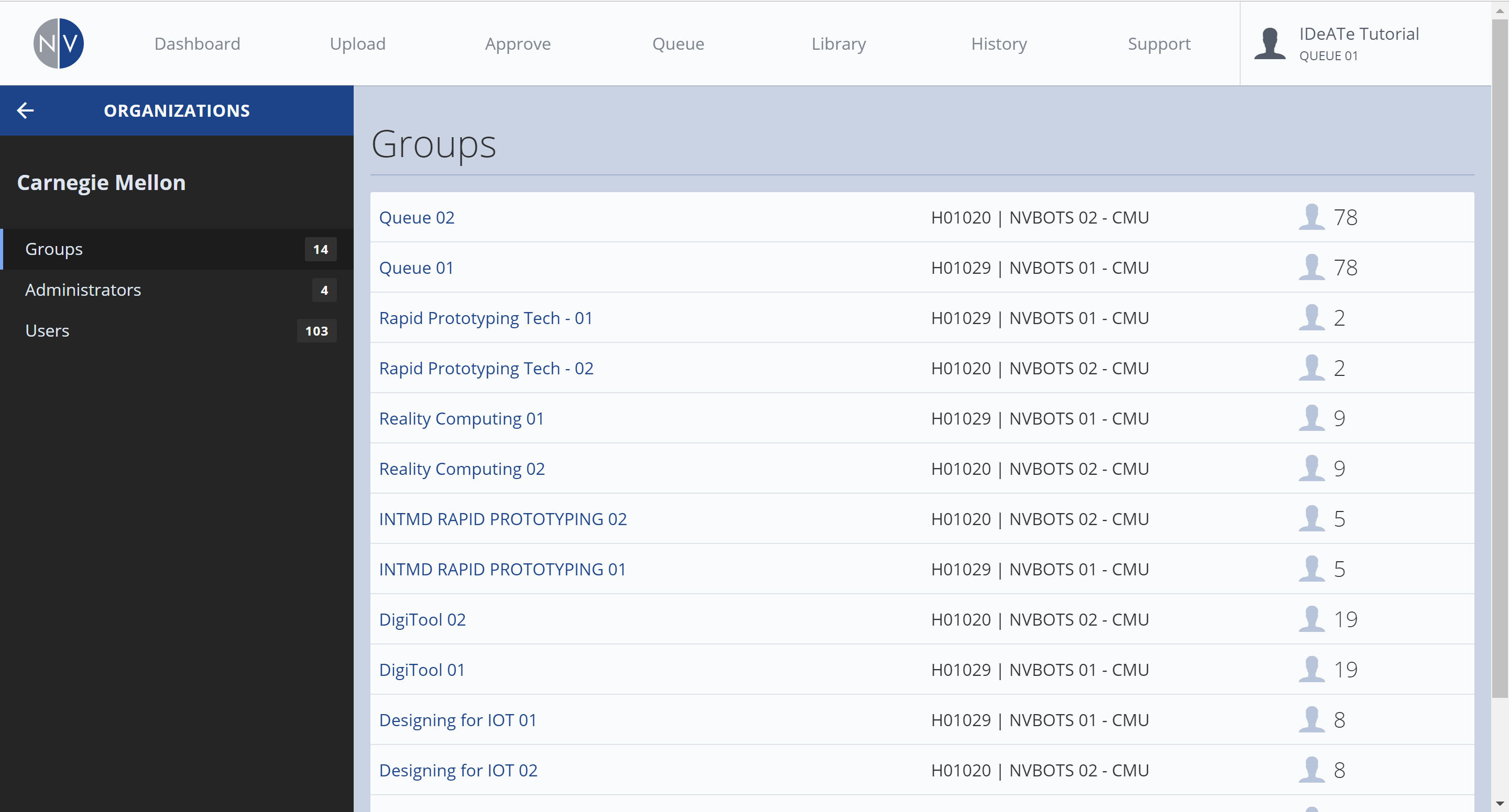
Near the bottom-left corner is your GROUP MENU. Selecting the arrow will expand this menu, allowing you to select which print group (and printer) the print should be sent to. The list is limited to print groups you’ve been invited to print from. *For more information on GROUPS, see NVBot: NVCloud Interface.


3. Submit
Submit your prepared print by selecting the SUBMIT button in the bottom-center of the NVCloud interface.

Review Process

After submitting your file, review relevant print job details to make sure all settings are correct and print cost is affordable.


1. Review: Approve Queue

After submitting a print job, your file is moved to the approve queue. Selecting the APPROVE tab will provide you with a list of 3D Prints waiting to be approved (ordered by submission time/date), with your recent submission included.

Immediately after submitting a print job, the right-most column of your print job listing, will indicate the file is ‘SLICING’. This process may take some time, as the toolpaths for the print job are being generated.

2. Review: Print Details

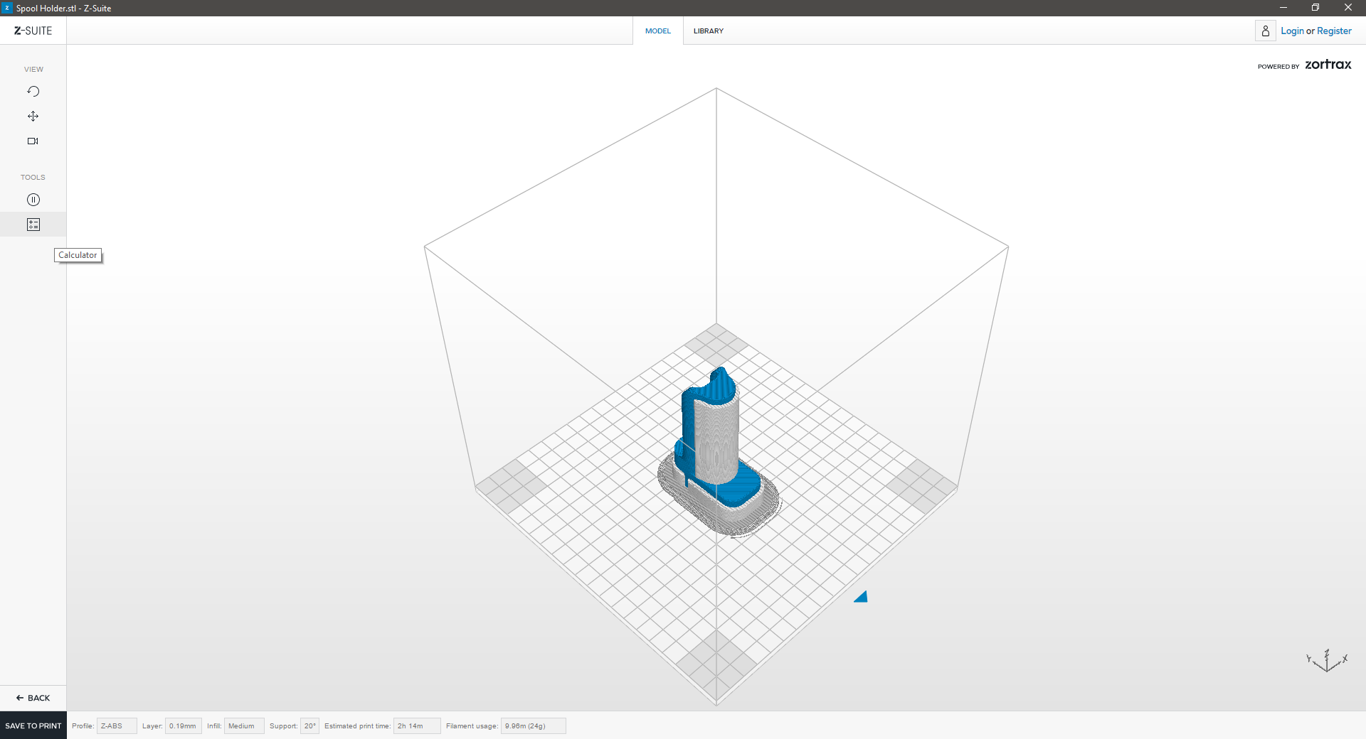
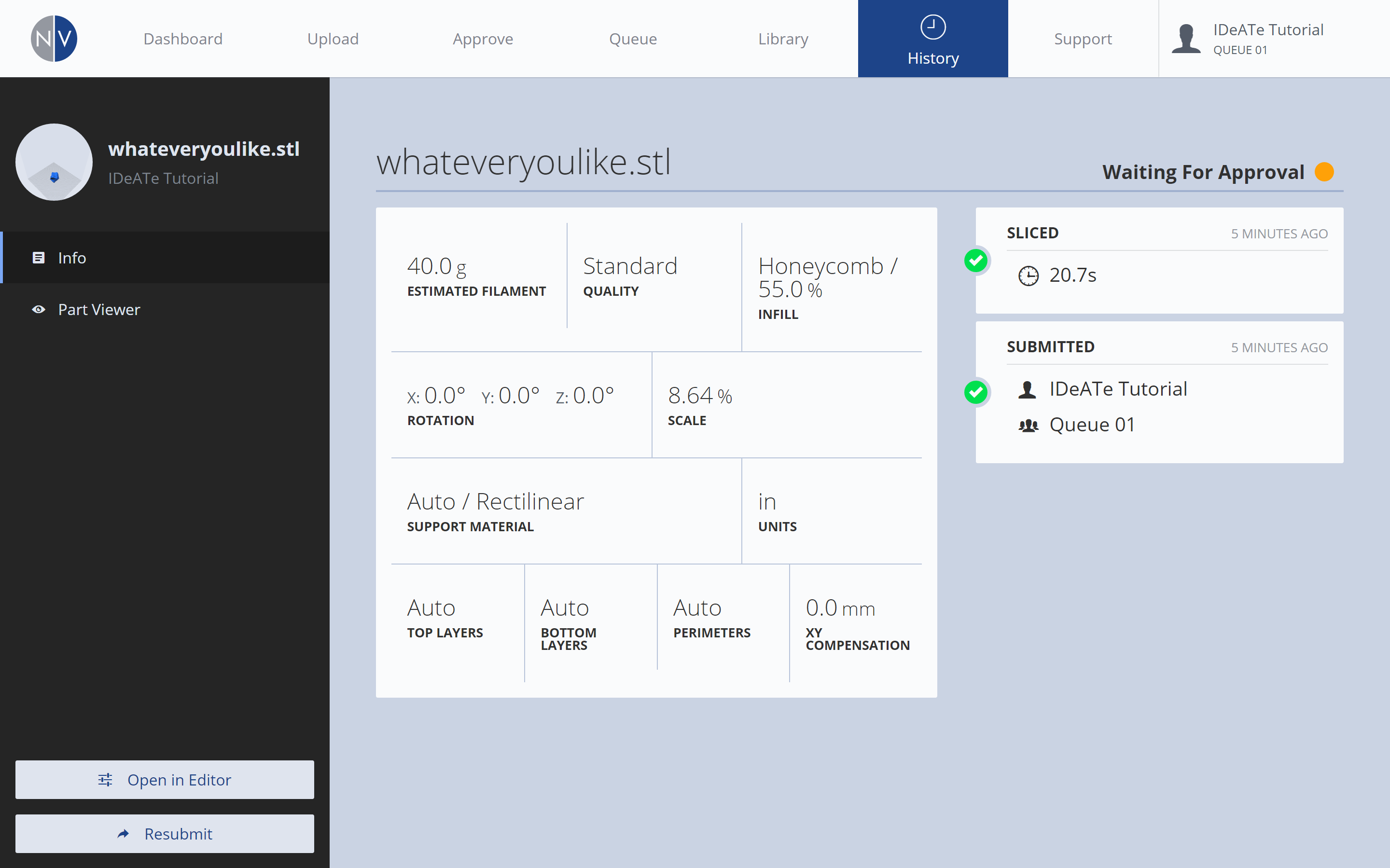
After the print job finishes the SLICING process, selecting the print job title or thumbnail will guide you to a new window with the print details. Review the following:

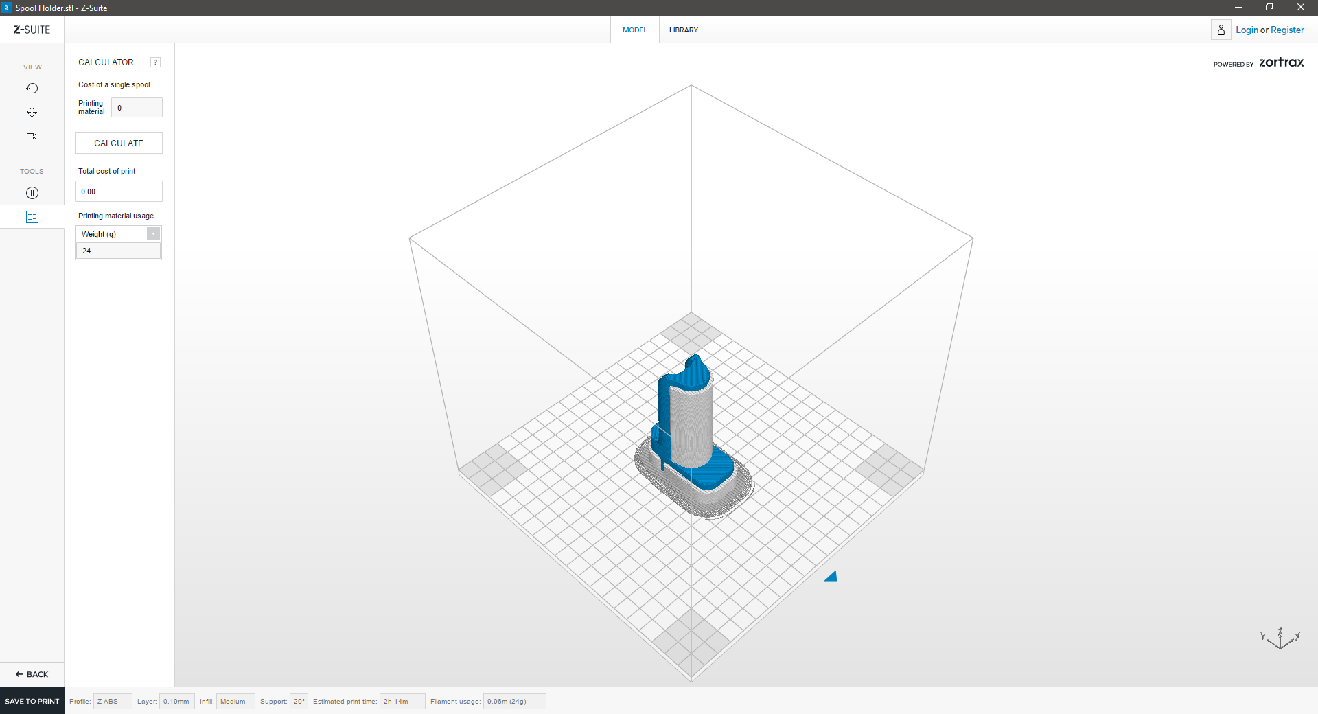
Estimated Filament/Cost: An estimate on the job’s filament usage is provided. Multiplying this number by IDeATe’s 3D Printing price, will provide you with an estimated cost for your print job. e.g. (IDeATe 3DPrint Price) x (Estimated Filament) = (Estimated Cost) Make sure you’re ok with the estimated cost!

i. *IDeATe 3D Print Pricing = $0.10/g (*Fall 2016 & Spring 2017)

ii. *Estimated Filament  = 40 grams (example only)

iii. Estimated Cost Example: ($0.10) x (40g) = $4.00

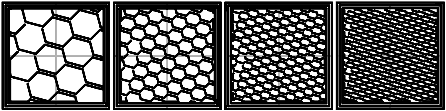
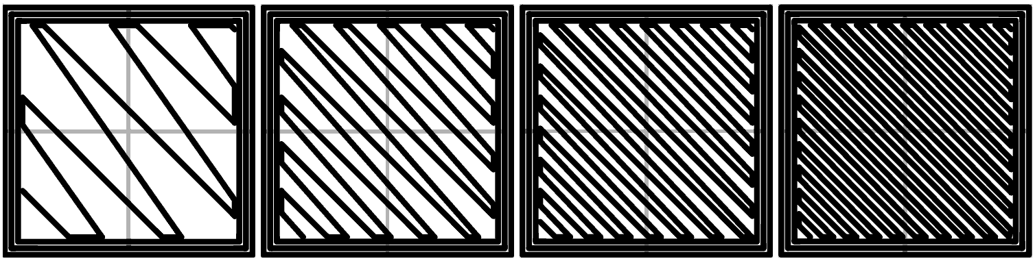
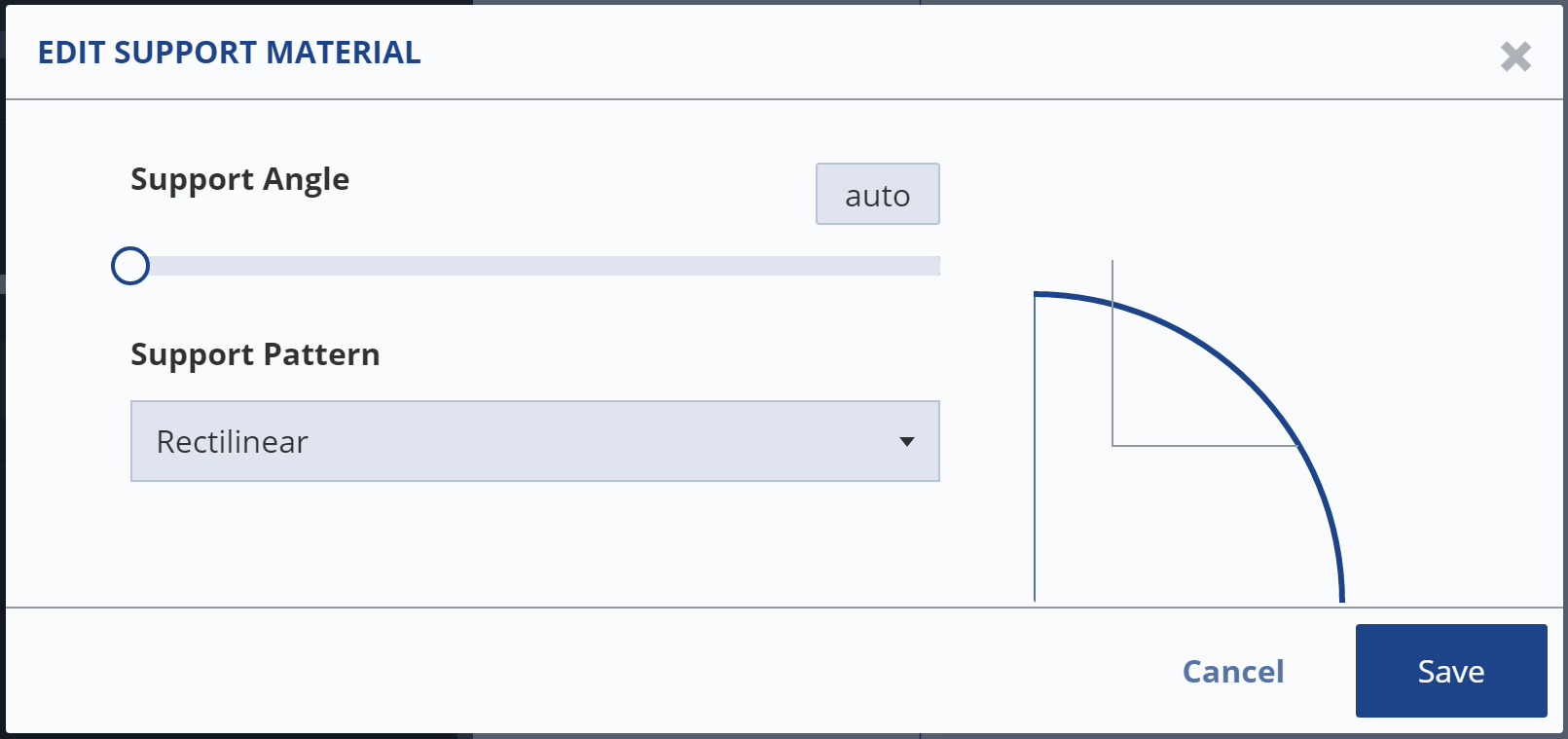
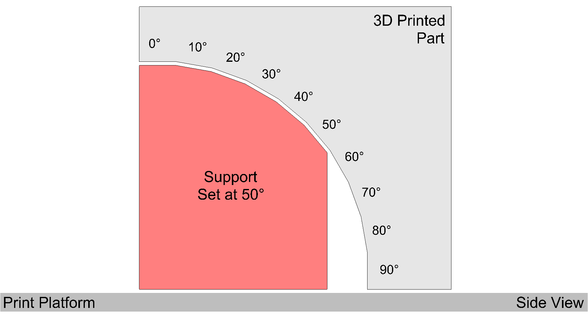
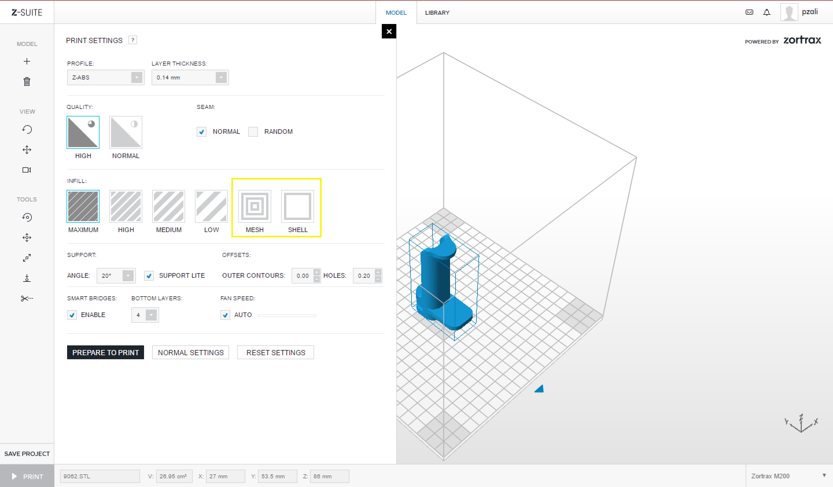
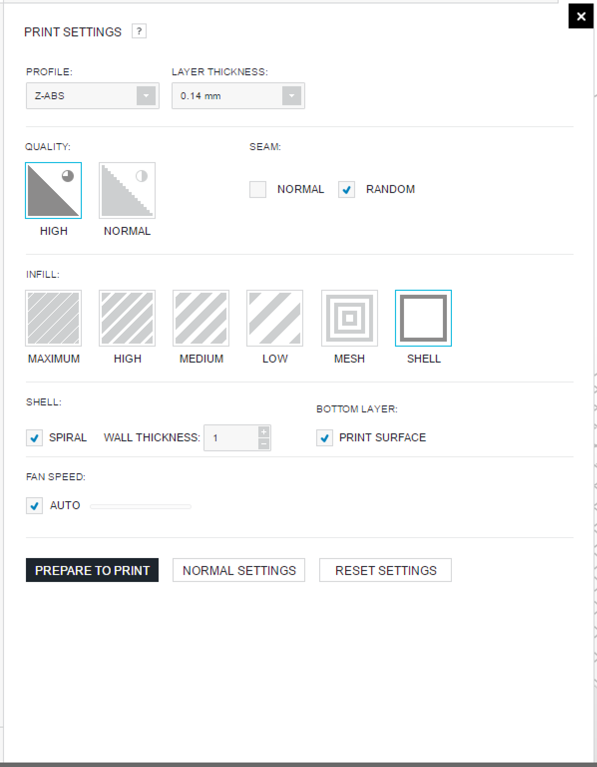
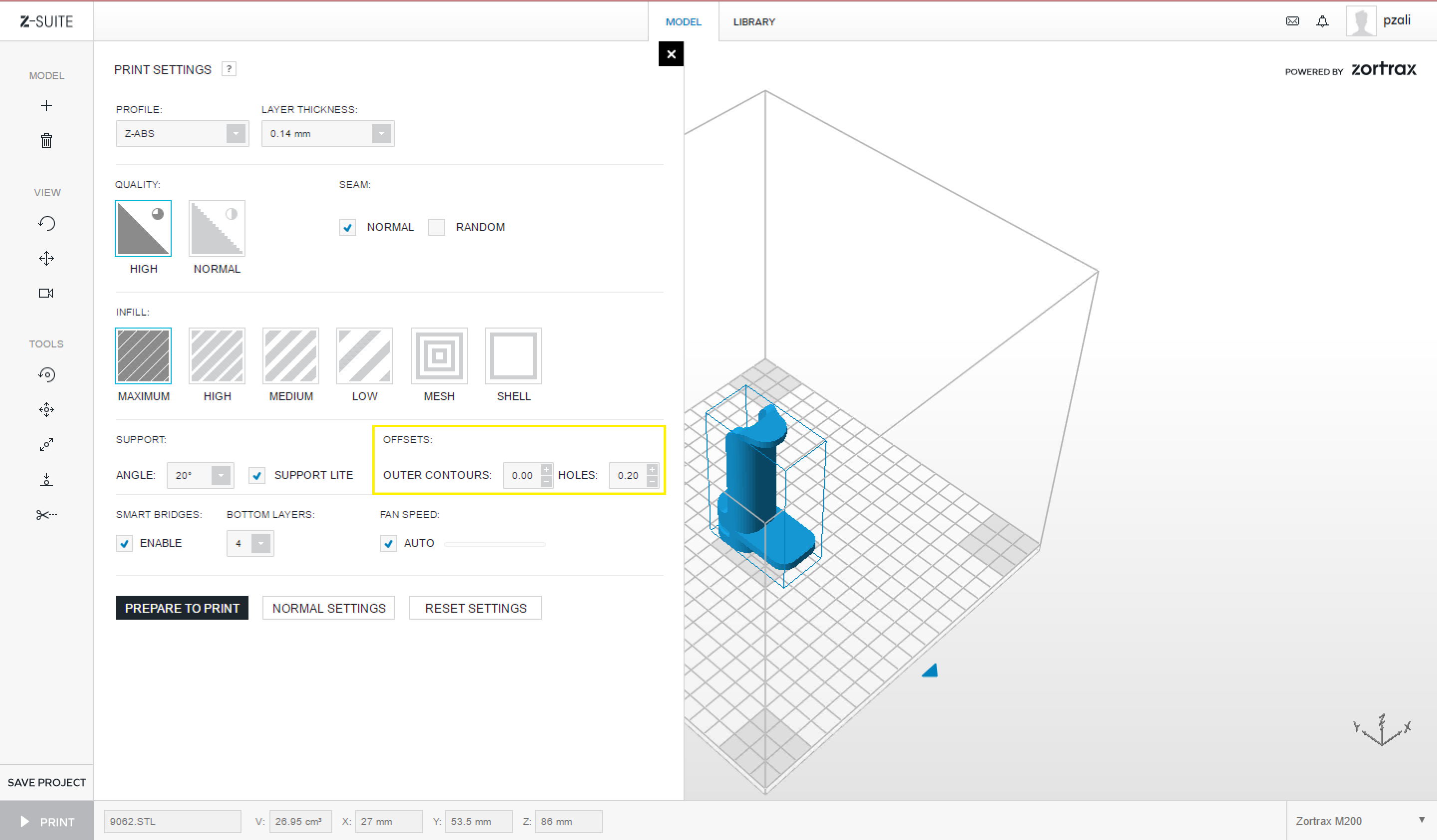
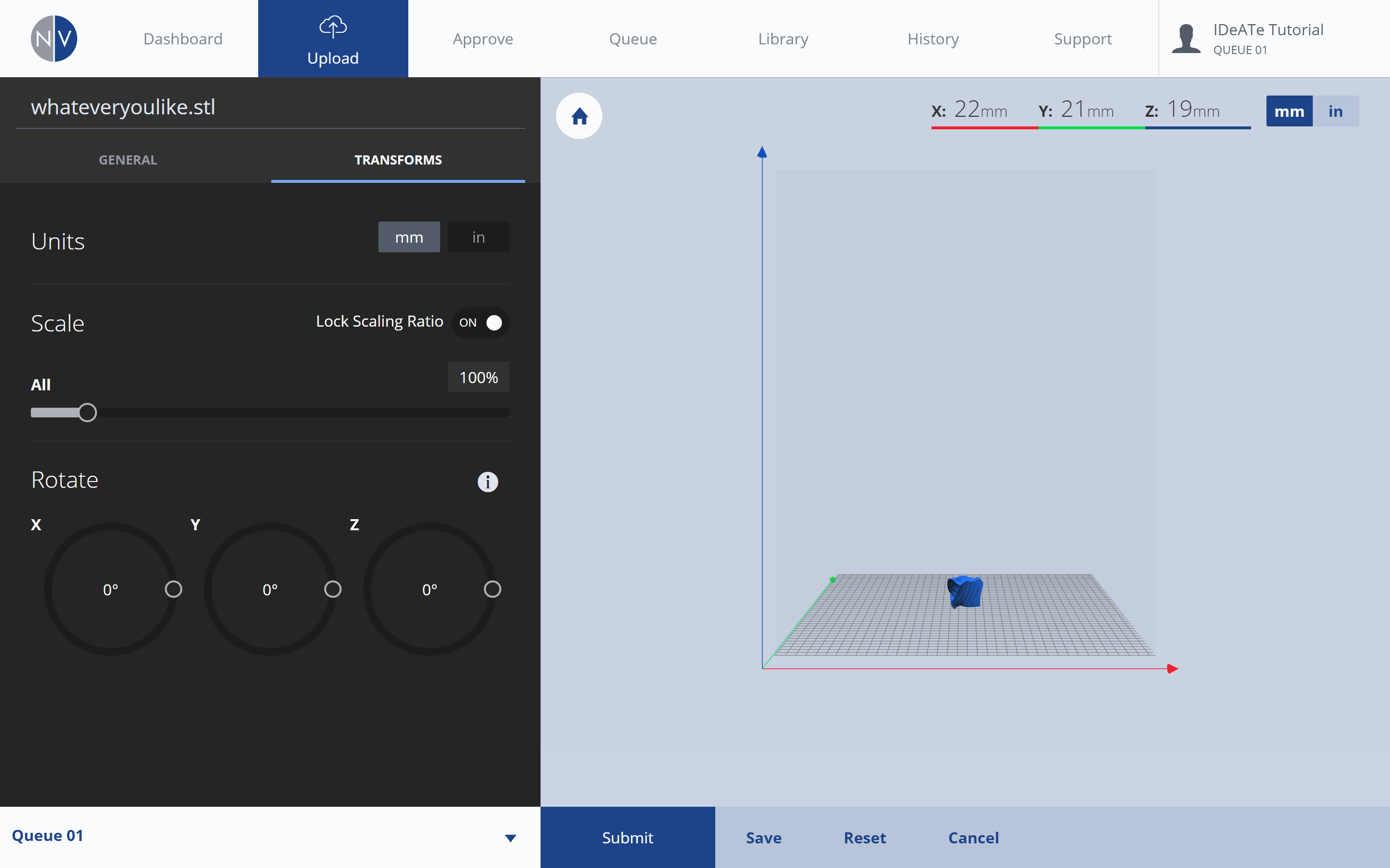
General Settings: Make sure the QUALITY, INFILL, UNITS, SUPPORT, ROTATION, SCALE and other miscellaneous settings are correct.

3. Review: Part Viewer – MODEL
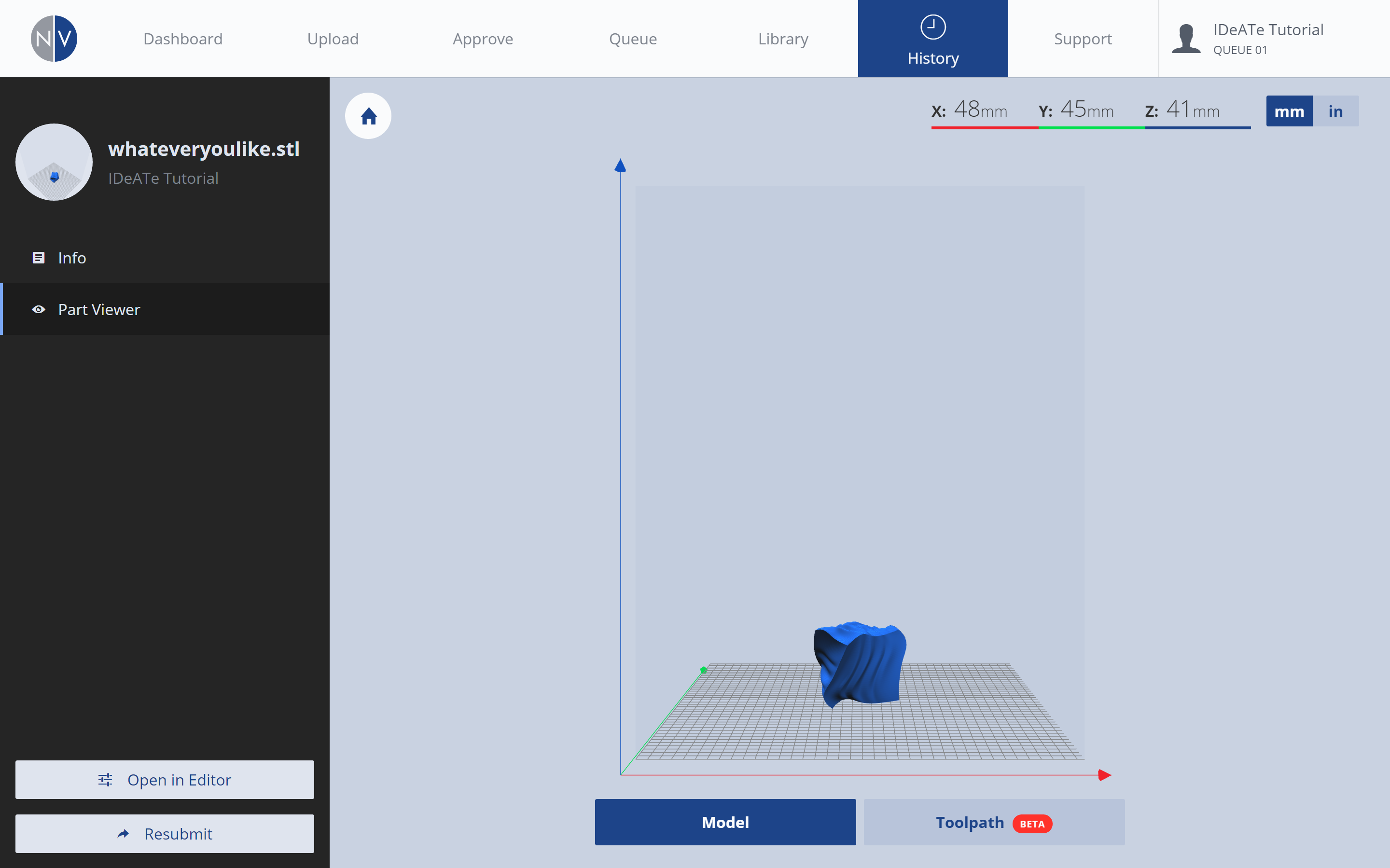
From the left-menu, selecting the PART VIEWER option, will provide you with a preview of your print job geometry. This is the default MODEL view.
4. Review: Part Viewer – TOOLPATH
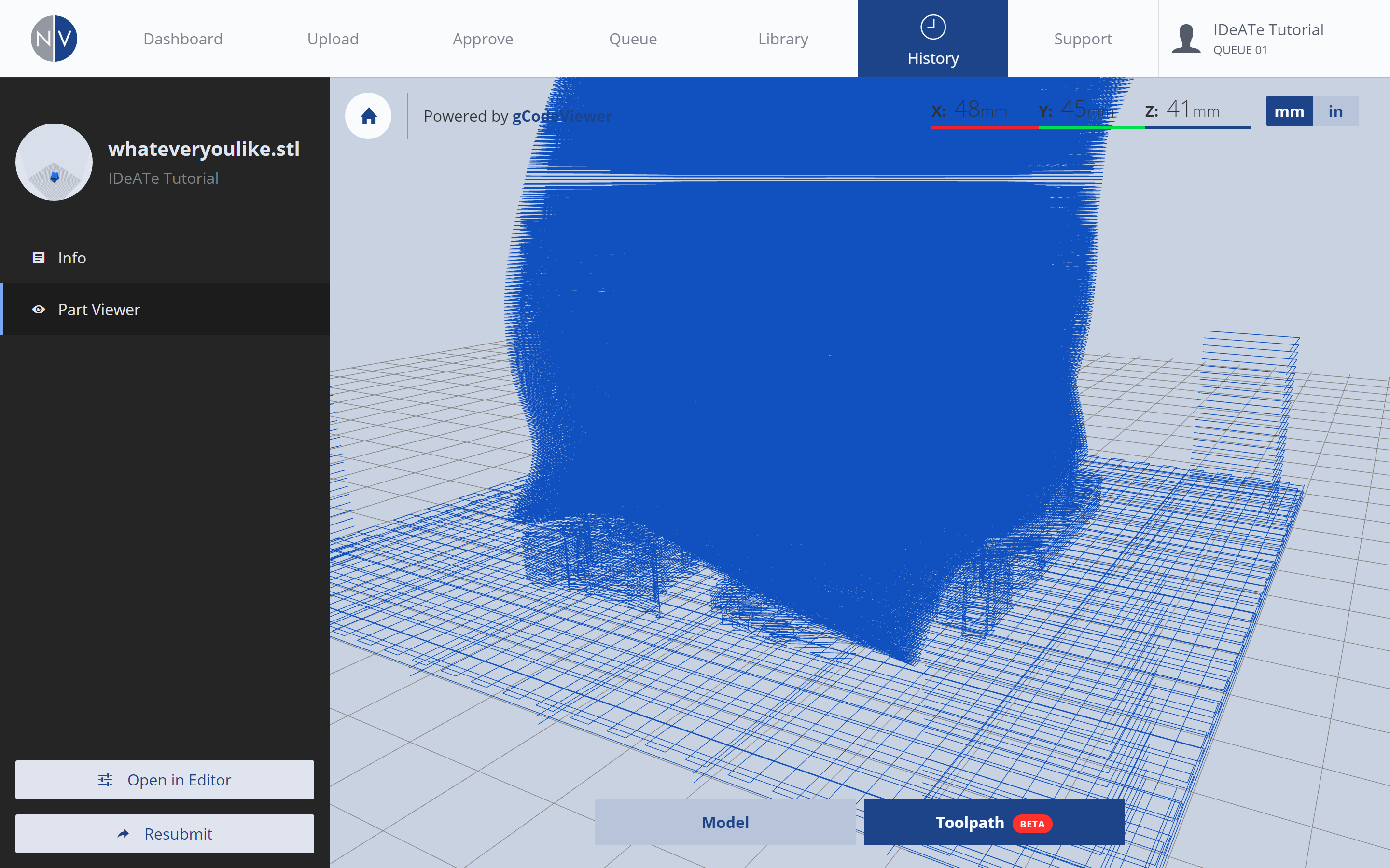
Selecting the TOOLPATH button, near the bottom-right of the screen, will present a visual representation of the toolpaths for your print job.
5. Review: Adjustments

If you find any errors with your print job, select the OPEN IN EDITOR button, from the bottom of the left menu. This will re-open the PRINT SETTINGS menu. From this menu, you can make any required adjustments to your print job, and re-submit.

*IMPORTANT: if you resubmit a print job with revised settings, your original print job will still exist in the approval queue! Revisit the APPROVE tab and delete any print jobs you do not want!

Approval Process

After you’ve reviewed your print job details, the job will remain in the approval queue until it is approved by IDeATe Faculty or Staff.


1. ORDER: Print jobs are approved on a first-come, first-served basis.

2. REVIEWERS: Print jobs may be reviewed and approved by IDeATe Technical Staff, Technical Advisors, Faculty, or Teaching Assistants.

3. WAIT TIME: Print jobs are approved in small batches. This eliminates any queue problems when a print job fails or if the printing equipment requires maintenance. It is normal for print jobs to remain in the approval queue for a short period of time (1-3 days) before being approved and moved to the print queue.

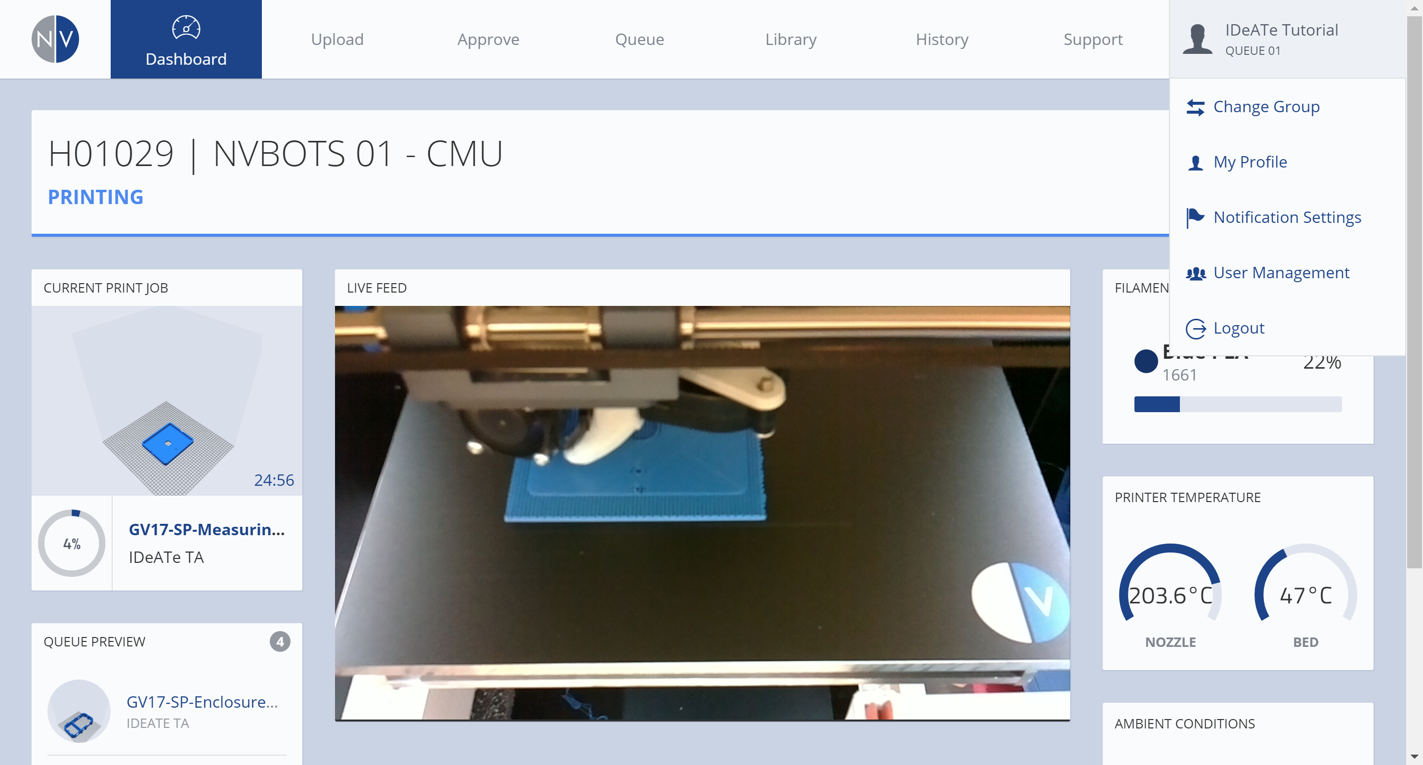
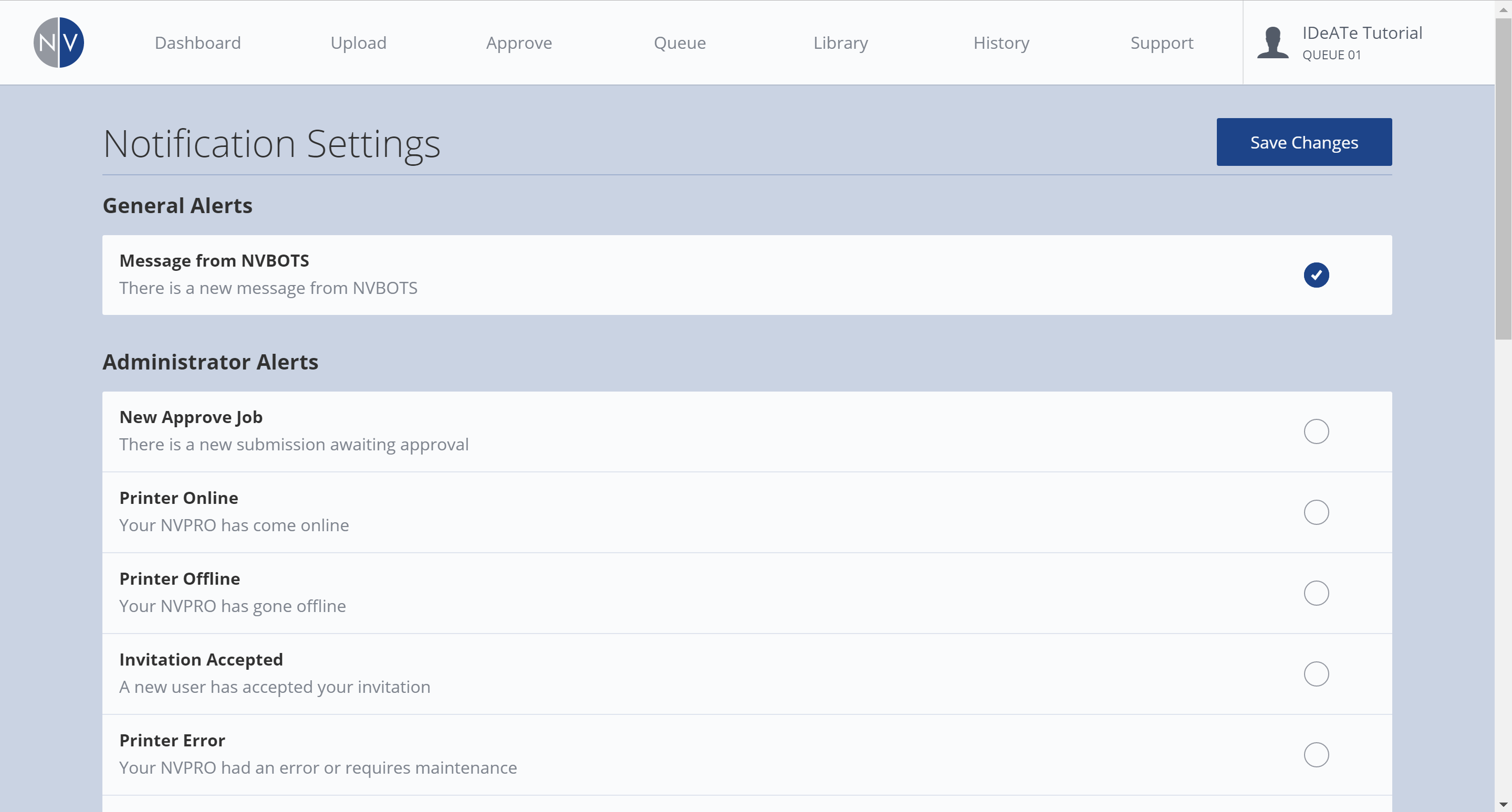
4. NOTIFICATION: *You will receive an email notification when your job is approved or denied. Please read the email, as it may include relevant notes or questions from the person who approved or denied your print. *If you aren’t receiving emails, you may need to adjust your personal notification settings (opens in new tab, login required).

Final Steps

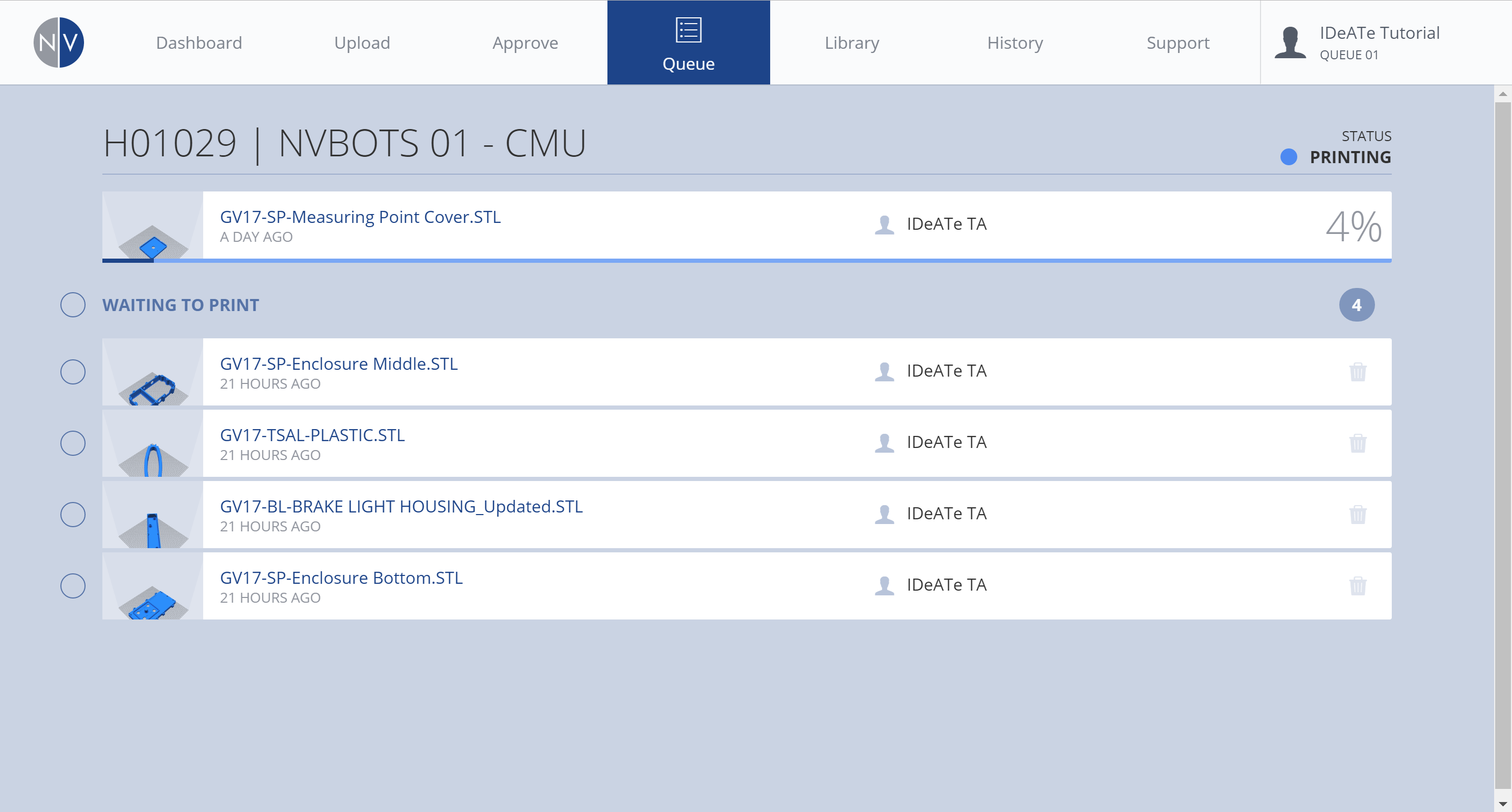
After approval, your print job transitions to the print queue.


1. ORDER: Print jobs are completed on a first-come, first-served basis.

2. PRINT ERRORS: If a print job fails due to equipment failure, you are not charged. The equipment will be fixed, and your file will be resubmitted as first in the print queue.

3. PRINT FAILURES: If a print job fails due to file preparation or geometry errors, you are not charged for the first instance. You may resubmit your print job after reviewing the errors with your Instructor or IDeATe Technical Staff. Any print failures occurring after this review are charged to your student account.

4. NOTIFICATION: *You will receive an email notification when your job begins and completes. Additional notifications are sent if a print is stopped or fails. *If you aren’t receiving emails, you may need to adjust your personal notification settings (opens in new tab, login required).

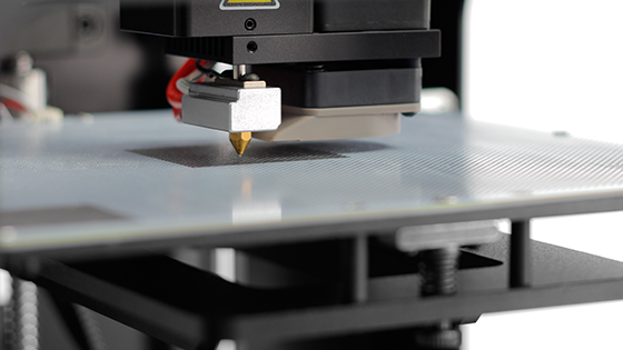
5. RETRIEVAL: Your print job will be scraped from the print platform, and dropped into the bin on the right-side of the equipment. Open the equipment door and retrieve your print.

6. CONTACT: If you’re encountering issues or you have general questions that are not included in the NVBot Tutorials, please:

a. Ask your instructor! If he/she isn’t available, then….

b. Ask a friend! I’m sure one of them will know. If you don’t have any friends, or you’re friends don’t know, then….

c. Make some friends who do know! Ask an IDeATe Tech Advisor! They wear the blue shirts that say: “Tech Advisor”- usually available on weekdays 4:30-7:30pm.

d. Email us: HELP@ideate.cmu.edu

NVCloud: Print Settings

NVCloud’s print settings allow you to prepare your geometry for printing. Print settings for new uploads are accessible immediately after uploading a Sterolithography [.stl] file. Print settings can also be accessed by selecting a previously uploaded, saved or printed file.


Quality

This option is available from the GENERAL print settings menu. QUALITY settings affect the layer height, overall surface finish and printing speed.


General: Quality

Fast = faster printing + 0.3mm (0.0118in) layer thickness. Use these settings if you’re in a rush or if part is a prototype.

Standard = slower printing + 0.2mm (0.008in) layer thickness. Use these settings for organic shapes or finer detailed printing.

Strength

This option is available from the GENERAL print settings menu. STRENGTH settings affect the infill density and pattern on the inside of the printed part.


General: Strength

The Strength slider affects the infill density of the part. The infill pattern can be configured between honeycomb, rectilinear, line, and concentric. By default, these options are set to ‘AUTO’, but you may want to reconfigure these settings to increase the strength of your final part.

High density (55-75%) = slower printing + increased expense + increased strength.

Medium density (35-54%) = average printing + average expense + average strength.

Low density (5-34%) = faster printing + low cost + low strength.

HONEYCOMB infill pattern. Offers average wall strength with increased compression strength. Infill density from left-to-right: 18%, 37%, 55%, 75%

RECTILINEAR infill pattern. Each infill layer will print in an alternating direction. Offers increased wall strength with average compression strength. Infill density from left-to-right: 18%, 37%, 55%, 75%
LINE infill pattern. Each infill layer will print in an alternating direction. Offers average wall strength with limited compression strength. Infill density from left-to-right: 18%, 37%, 55%, 75%
CONCENTRIC infill pattern. Offers limited wall strength with limited-to-average compression strength. Infill density from left-to-right: 18%, 37%, 55%, 75%

Support

This option is available from the GENERAL print settings menu. SUPPORT MATERIAL settings affect support generation methods and patterns.


General: Support Material

Support structures are necessary in supporting 3D printed parts with overhangs, bridges, or undercuts. If your geometry includes any of these features, the SUPPORT MATERIAL button should be switched ‘ON’.

Select the EDIT button to adjust the support angle and pattern.

The ANGLE value defines the angle at which support structures are generated for over-hanging or undercut geometry. It is recommended this setting be left as default: AUTO.

AUTO Angle Value = average print success + average print cost + efficient print time. This option is recommended. The printer will determine when it requires more or less support.

Higher Angle Values (75-90 Degrees) = increased print success + extreme increase in print cost + extreme increase in print time. The removal of support material from your final part will also prove quite difficult.

Average Angle Values (45-74 Degrees) = increased print success + increased print cost + increased print time. These values are safe.

Lower Angle Values (0-44 Degrees) = lower print success + lower print cost + lower print time.

 For instance, a support setting of 50 Degrees would print support structures for overhanging geometry that is less-than or equal-to 50 Degrees. An example is provided in the image above.
 As a second example, a support setting of 10 Degrees would print support structures for overhanging geometry that is less-than or equal-to 10 Degrees.

Units

This option is available from the TRANSFORMS print settings menu. UNITS option allows you to switch between (mm) or (in).


Transforms: Units
Stereolithography [.stl] files do not preserve units of measurement (e.g. inches, millimeters, miles, light years etc.). However, they can preserve unit values (i.e. 10 x 10 x 10). If you find your geometry appears too small or large, begin by adjusting the UNITS value.

Scale

This option is available from the TRANSFORMS print settings menu. SCALE option affects the scale of the part.


Transforms: Scale
The Scale slider affects the scale of the part. The Lock Scaling Ratio button can be turned off to allow for independent scaling in the X, Y, and Z axes.

Rotate

This option is available from the TRANSFORMS print settings menu. ROTATE option affects the orientation of the part.


Transforms: Rotate
The Rotate slider affects the orientation of the part. Note: Holding the SHIFT key will snap the rotation angle to the nearest 45 degree increment

Misc

Bottom Bar Options

At the bottom of the NVCloud Print Settings window, various universal options are provided (from left-to-right):

GROUP BAR: This expanding menu allows you to select which print group (and printer) the print should be sent to. This is covered in NVCloud: Submission & Review.

SUBMIT: Selecting this button sends your file to the selected printing group for approval. This is covered in NVCloud: Submission & Review.

SAVE: Select this button to save your print file and settings. Your file can be retrieved at any time, by browsing to the LIBRARY tab and selecting SAVED PARTS* in the left menu. (*Link opens in new tab, login required)

RESET: Select this option to reset the print settings and any transformations you’ve applied.

CANCEL: Select this option to exit the print settings menu. Your uploaded file and any adjustments will be discarded.

Post

Info

What is a Post?

A POST DEFINITION file is a unique translation document, defining multiple variables and lines of code that are specific for Computer Numeric Controlled Equipment. Think of this as a dictionary, of sort.

A POST PROCESSOR creates, arranges, and formats lines of code between CAD Geometry, CAM Operation settings and the Post Definition File.

Commonly referred to as the “POST“, this is the final-formation of code, that guides the CNC Equipment based on the previously prepared CAD & CAM settings defined by the user.

(CAD + CAM + POST DEFINITION) + (POST PROCESSOR) = POST

Download

Post Definition Files

To create a POST, you will need a POST DEFINITION file. The following POST DEFINITION files are unique to IDeATe CNC Equipment, and should not be used for any other CNC Equipment.

Post Definition File : Standard, Inches

Post Definition File : Metric, Millimeters


Instructions

1. POST: Download
Download & save the Post Definition file. Make note of where the file is saved.
2. POST: File Location

From the Machining Operations Browser, the Post Definition File can be adjusted by double-clicking one of the following:

1. POST: Located as the second option down, from the PROGRAM tab, directly below the MACHINE option, int the MACHINE SETUP bar.

2. POST – XXXX: Located as the second option down, from the MACHINING JOB Tree, directly below MACHINE – 3-AXIS & above STOCK – NONE.

3. POST: Select
A new window titled SET POST-PROCESSOR OPTIONS will appear.

1. FOLDER: Begin by browsing to the folder, where the recently downloaded Post Definition file is located.

2. CURRENT POST PROCESSOR: IF there is more than one Post Definition file in the previously selected folder location; select the drop-down arrow to select the correct Post Processor.

NVBot: NVCloud Interface

Dashboard

Dashboard

The DASHBOARD provides quick details on your current 3D Printer & Group. From this tab, you can view:

Printer Name & Status header: IDeATe has (2) NVPro Printers, named ‘NVBOTS 01 – CMU‘ & ‘NVBOTS 02 – CMU‘. This is relevant when retrieving your print from the printer. Print status’ can range from Error, Maintenance, or Printing.

Current Print Job is the file that is currently printing.

Queue Preview lists the next file in-line for printing.

Live Feed provides a camera feed for the current print job.

Filament details include the color & type of material being printed.

Printer Temperature & Ambient Conditions indicate temperature and humidity values, local to the equipment.

Profile

Profile
When hovering over the PROFILE tab, located in the top-right corner of the browser window, a drop-down menu will appear with additional options. Each option is described below, with the exception of LOGOUT.
Change Group

Selecting the CHANGE GROUP option, allows you to switch between any groups you’ve been invited to. Selecting and printing to the right group, may determine whether the print is billed to the course, or the student. There are (2) types of groups:

a) Course groups are created for each IDeATe Course that uses the NVPro Printer. Any course related printing should be submitted from the affiliated course group. Initially, you will receive an invite to join at least (2) course groups. The group title will reflect your course name, followed by a numeric label ’01’  or ’02’. Group titles ending in ’01’ provide access to NVBOTS – 01. Group titles ending in ’02’ provide access to NVBOTS – 02.

b) Two universal groups, QUEUE 01 & QUEUE 02, provide continued access to the NVPro printing equipment after your IDeATe course ends. These groups can also be used for personal or other non-IDeATe course related projects.

Profile
Selecting the PROFILE option, allows you to modify personal profile settings such as password, first & last name. Within this area, you can also view/access your printing history. This will be helpful in retrieving/viewing time-lapse videos of your print jobs.
Notifications
Within the NOTIFICATIONS option, you can adjust your personal notification settings. All of which are self explanatory, but helpful nonetheless.
User Management
The USER MANAGEMENT option, will provide you with a listing of all the existing groups & users for the NVPro printers. This area is primarily for Administrative purposes.

Upload/Approve/Queue

Upload
Selecting the UPLOAD tab, will allow you to upload a Stereo-Lithography [.stl] file into the NVCloud interface. After upload, you can begin preparing the print settings.


Approve

After you’ve uploaded a file, modified the print settings, and submitted the file for printing- the file is placed in the approval queue. When selecting the APPROVE tab, you can browse/view a list of 3D Print submissions that are awaiting approval. From this area, you can also select your print file, and review relevant information pertaining to the print job. (e.g. Estimated Filament usage for calculating price) If you find an error or mistake in the print job info, you can also cancel your print job from the APPROVE tab.

Approving print jobs is coordinated by IDeATe Technical Staff. You will receive an email notification when your print job is approved; unless this notification option is disabled from your personal notification options. *Find NOTIFICATION information under the PROFILE tab.


Queue
Once your print job is approved, you can view its order in the print queue from the QUEUE tab. *Unless notification options are disabled, email notifications are sent when your file begins and completes. Other automated notifications are sent if there are printing errors or if the print job is cancelled. *Find NOTIFICATION information under the PROFILE tab.

Library

Library
Within the LIBRARY, you’ll find several prepared files that are open source and ready to print. The print jobs are ready for printing, but they are charged to your student account.

History

History
Selecting the HISTORY tab will provide your printing history. This is helpful when retrieving/accessing timelapse videos of your print jobs. This is also helpful in retrieving information on print job status’. (e.g. Not Approved, Skipped, Success, Failure etc.)

Zortrax M200: Printing Platform

Remove

Removing the Print Platform

WARNING: HEAT HAZARD
Before removing the print platform, switch the equipment OFF, and unplug the power cable.
Unplug the heatbed cable from the platform. Both big and small connectors need to be unplugged.
Remove the platform by lifting UP and guiding out.

Clean

Cleaning the Print Platform

WARNING: CUTTING HAZARD

Put on the RUBBER GLOVES included in the Zortrax M200 Kit. The kit also includes a sharp-edge spatula. Place the platform onto a secure/steady table-top. With one hand holding the platform in an upright position, (gently) guide the spatula across the platform and AWAY from your body and hand. Remove as much material as possible.

*NOTE: Please notify IDeATe Technical Staff if there is any permanent residue you are unable to remove. DO NOT replace the platform unless it is clean and prepared for the next user.

Replace

Replacing the Print Platform
Open the front panel, put the platform back in the printer and plug the heatbed cable in. Both big and small connectors need to be plugged in.
Plug the power cable in. Turn ON the printer and wait until the plate heats up. Notify IDeATe Technical Staff of any issues when returning your M200 Kit.

Zortrax M200: Start Printing

Overview

1. Equipment Overview
The Zortrax M200 is enclosed with (3) semi-transparent plastic shields. (not pictured) When opening front shield/door, you can access the internal parts & pieces. When the equipment is in operation, this door should remain closed.

Inspection

2. Inspect the Perforated Plate

WARNING: HEAT HAZARD

The perforated plate is mounted (with screws) to a heated build plate that attaches magnetically atop the build platform. Before printing, inspect the perforated plate; make sure the plate is free from large debris and leftover material. It is normal to have leftover material embedded within the perforations. If the perforated print platform is sufficient, continue on to the next step below.

If the perforated print platform requires cleaning, follow the instructions on removing, cleaning and replacing the Zortrax M200: Printing Platform.

Load

3. Load your Print File
Open the front panel and locate the SD card slot. The reader is positioned in the front-right of the machine, above and behind the display interface. Insert your SD Card and close the front panel.

i. Using the rotating control knob, browse to item labeled MODELS on the M200 display. Select this option by pressing the control knob.

ii. In the next menu, a list of [.zcode] files will appear. Scroll to your file and select.

iii. In the final menu, the display lists the selected print file’s details (Material Profile & Est. Print Time) near the bottom. Two options are available from this Menu:

> Select BACK to move to the previous screen.

>Scroll to PRINT: YOUR_FILE_NAME.zcode and select, to begin your print job.

If you select PRINT, the equipment will begin heating the build platform, print head, and the internal environment. Make sure the front panel is shut, and close any sliding doors on the 3D Printer fume hood.

Z-Suite: Slice & Save

Prepare to Print

Prepare to Print: Slicing

Within your Print Settings window, selecting the PREPARE TO PRINT Button will begin preparing your 3D Model for 3D Printing. This process is commonly called ‘slicing’. During which your model is ‘sliced’ every ‘x‘ amount of (inches or millimeters). *Where ‘x‘ = Layer Thickness. This process, determines how support and model material are printed on each layer.

The final on-screen result will provide a print-preview, where model material print zones are indicated in blue, and support structures detailed in white. Additionally, the bottom-most panel in Z-Suite, will provide you with details such as: *Material Profile, *Layer Thickness, *Infill, *Support, Estimated Print Time and Filament Usage.

*These settings are detailed in Z-Suite: Print Settings

Inspection

Inspection *Optional
Z-Suite provides an option to insert PAUSES in your print file. This option is not currently supported with IDeATe (Zortrax) M200’s. However, you can use this option to inspect how your part will print on a layer-by-layer basis. Find and select the PAUSE button from your left menu.
After selecting the PAUSE button, a PAUSE menu will expand from the left. Near the top of the menu, an adjustable bar (indicating print progress) allows you to scroll through the print; from layer #1 (0%) to the final, top-most layer (100%). Although this is not a required step, it is interesting nonetheless. Find and select the REMOVE ALL button, then collapse/exit the menu by re-selecting the PAUSE button.

Cost Calculator

Cost Calculator *Optional
*Z-Suite provides an option for Cost Calculation. Find and select the CALCULATOR button from the left-hand menu.

After selecting the CALCULATOR button, a CALCULATOR menu will expand from the left. One value should be adjusted, before receiving a proper cost estimation:

**PRINTING MATERIAL: This value represents the total cost of a single spool. For IDeATe (Zortrax) M200 Printers, this value should be set to ’80’.

**Find and select the CALCULATE button to update the TOTAL COST OF PRINT value. This represents the total cost of the print job. In IDeATe, this averages around $0.10/gram of material used.

Find and re-select the CALCULATOR button to exit this menu.

Important Notes:

* As of JAN-17-2017, 3D Printing in IDeATe Print Lab (A5b), on Zortrax M200‘s is provided FREE OF CHARGE.

** Material pricing is based on Purchase Price, Shipping Costs, and average successful vs. failed 3D Print jobs. *You are not charged for failed print jobs.

Save

Save to Print
When you’re ready to print, find and select the SAVE TO PRINT button from the bottom-left of Z-Suite. The (Zortrax) M200 is NOT directly connected to the computer. You will have to save your print file (File format: .zcode) to a memory card. Memory Cards are available for borrowing in IDeATe Lending (A29).
Browse to a file/folder location, and save your file. Once the file is saved to a memory card, eject the card from the computer and transition to the M200 Equipment.

Z-Suite: Advanced Print Settings

Advanced

Advanced Settings
Selecting the ADVANCED SETTINGS button will expand your Print Settings window, and provide you with additional options.

Seam

Seam
SEAM: Each print layer, by default, begins in the same (X,Y) Coordinates as the previous layer. Seam options allow you to maintain this setting, or change it to RANDOM.
Leaving the SEAM option set to NORMAL, retains the default print settings. In the image above, each black square represents a 3D printed layer. The red dots indicate each print-layer’s starting point. This is an example of the default setting, NORMAL.
Changing the SEAM option to RANDOM, modifies each print-layer’s starting point. In the image above, each black square represents a 3D printed layer. The red dots indicate each print-layer’s starting point. This is an example of the RANDOM option.

Infill

Infill: Mesh & Shell
Two (2) additional INFILL options are provided in the Advanced Setting Menu, MESH & SHELL.
MESH: Prints the model with 0% infill. The top & bottom (horizontal surfaces) and walls (vertical surfaces) are all printed.

SHELL: Prints the model with 0% infill. The top & bottom (horizontal surfaces) surface layers are also removed. When the SHELL setting is selected, an additional option menu appears directly below:

SPRIAL: Adjusts the seam/starting point of each printed layer. This is described in detail, on the previous tab SEAM. (Recommended)

WALL THICKNESS: Adjusts the wall thickness (in layers). (Recommended 2-3 Layers)

BOTTOM LAYER: Retains and prints the bottom surface layer of your 3D Model. (Recommended)

Offsets

Offsets: Outer Contours & Holes

OFFSETS: These options allow you to increase the wall thickness of any vertical or hole surface geometry.

OUTER CONTOURS: Increases the wall thickness for any vertical surface geometry. The input value will increase the thickness of walls in BOTH directions. This will increase the strength of your print, but also changes the internal & external dimensions of your model.

HOLES: Increases the wall thickness for any circular openings/holes. The input value will increase the thickness of walls in BOTH directions. This will increase the strength of your print, but also changes the internal & external dimensions of the hole(s).


Smart Bridges

Smart Bridges
SMART BRIDGES: Enable this option if you wish to print an object with small holes. This will eliminate any printing of support structures within these holes. With this option enabled, removing the support structure within the hole(s) is not necessary. This option is recommended for Models that include hole(s) that are less-than or equal-to 8mm in diameter.

Bottom Layers

Bottom Layers
BOTTOM LAYERS: Increases the thickness of your model’s bottom-most surface. This increases the strength on the bottom of your printed model, which is helpful when removing the part from: a) the printing platform & b) any base level supports.