For my final project, I made a responsive worm that normally wiggles around on the ground, but when a person comes too close then will look up at the person.
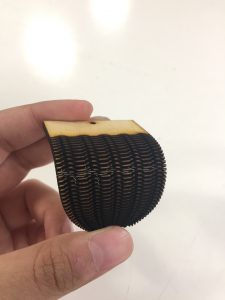
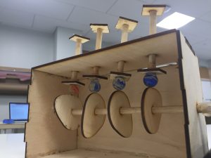
The main challenges for this project was trying to keep the form factor I wanted it – I really wanted the worm to be lasercut wood but getting the wood to bend at the appropriate angle took a fair amount of testing. I found a solution by using two servos that pull the the wood back and keep it in place. Finally, the aesthetics took a good deal of time to try to cover up the circuitry and motors to make it just look like a worm in a tank.
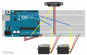
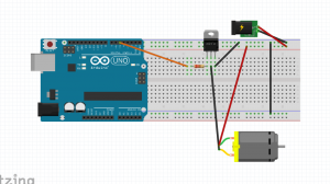
The circuitry and code in itself was quite simple – an analog IR sensor and two servos that pull at string that actuates the worm. However, I think this was a good strategy because of how many iterations the worm movement took to look somewhat good.
For my rough crit, I have a prototype of the mechanical “worm” that can move in a couple of dimensions and is actuated by the Arduino. Moreover, I have also ensured that I can get data from an IR sensor and a microphone, but will need to choose which sensor to use based on the final form of my tank.
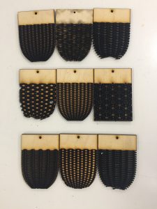
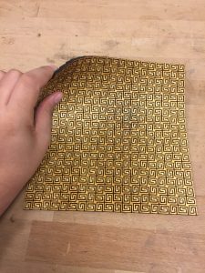
The mechanical form took a great deal of prototyping to figure out a good mix of flexibility (especially in multiple angles) as well as durability, as I found out rather painfully that many of these patterns broke rather quickly. Moreover, another trade off became very apparent with weight and movement, as not only did it require more strength to move but also it means I have to tamp down the other part of the board.
Additionally, I had originally planned to actuate the system using muscle wire, but it ended up being too weak to move the worm. Therefore, as a work around, I actuated the worm using string and servo motors – the servo motors pull up the string, which are attached to specific points around the worm and then pull up the worm accordingly.
However, I’m trying to get a more natural movement, so I might have magnets on the underside of the wood so that way there is only a small part of the wood that peeks up with every string.
For my final project, I will be making a “mechanical worm” in a cage that responds when someone taps the glass case around it.
My original idea was to make a geometric wood lamp shade that had the ability to “open up” or “collapse” that could be controlled using muscle wire or a motor. However, I wanted something with a bit of a better interaction, so the muscle wire and wood actuation will actually be quite similar still, just packaged in a different story.
I’m thinking for my form, the worm will be placed in a little enclosure as below that will either be filled with a mix of natural and plastic items to create this sense of a mechanical/artificial world.
Hardware:
Wood needed to make the worm
Some type of motor/muscle wire to actuate the worm
Arduino and external power supply
Some type of hand sensing (IR camera?)
Software:
Some software needed to use the body sensing hardware (perhaps, Max that sends signals over OSC to the Arduino)
Order of construction and testing:
create the mechanical system of the worm
actuate the lamp using dc motors or muscle wire for simple movement
set up the “tap” sensing feature
have the worm set up in the cage and create different interactions per type of tap, plus what the worm will be doing in its “normal state”
have the worm tested in an environment with lots of people and see how it works
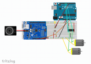
For my Halloween project, I wanted to do something that involved playing the Scooby Doo theme song (as illustrated in my prototype) and some type of motor/sensor action that involved the gang and maybe some monsters. I was not really pleased with the quality or length of the sound that I achieved in my prototype, so I decided to pursue using the Music Maker Adafruit shield which uses an SD card to play songs (which would give me longer music length and better quality as I would no longer be using the Arduino as my storage device). After a lot of struggling, I got the full theme song playing such that when it got to be “nighttime” (based off my photoresistor) the song would play in its entirety. However, I think this Music Maker shield + the photoresistor got to be too much for my Arduino (and I think some pins might have been fried in the process), so I had originally connected the wheels of the Mystery Machine straight to power and ground so I could get some motor action.
I then spent a decent amount of time trying to make some workaround to get some motor and LED interaction from the light sensor. I realized that an easy solution without messing too much with the Music Maker set up would just to use a second Arduino that gets the same input from the photoresistor that connects to the Music Maker and instead just runs the data to an h-bridge and an LED. After some simple issues of downloading code to the wrong board, I was able to get this system up and working.
My final project now works such that when it gets to be “nighttime,” the wheels of the Mystery Machine start spinning, its headlights turn on, and the Scooby Doo theme song plays. The whole system is completely functional!
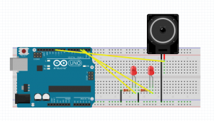
For the Halloween centered project, I wanted to make a project that was an homage to Scooby Doo: I wanted a monster (with flashing red LED eyes) to “run” towards the gang (using two servos) while the gang all while the gang “runs” away (using two servos and a mechanical mechanism to connect their legs together), all underscored with the Scooby Doo theme song playing from a speaker. Therefore, for my prototype, I wanted to make sure that I was able to run electronics for the sound system, LEDs, and servos together.
As we were already well versed in getting LEDs and servos to work properly, I wanted to start off with the sound system, which turned out to be a lot more work than I thought. As it turns out, the most common way to play actual audio from the Arduino is to use an SD card and an SD card Arduino board to play audio. However, I wanted to see if there was a way to play audio straight from the Arduino, which was a surprisingly difficult task. After some searching, I found this instruction guide, http://highlowtech.org/?p=1963, which I followed to get the audio working. However, this system clipped the length of the audio much more than I wanted, but I figured this might be something I could work with. I then tried to also add basic LED and servo testing to make sure there were no clashes. Unfortunately, while the LEDs worked fine, the new library I had to add for audio actually conflicts with the inbuilt servo library.
After executing this prototype, I realize my options are 1) try using the SD card, SD card reader method for playing audio and having LEDs and servos working for my project
2) keep this audio method and do something only with LEDs, which is still a viable possibility for a good project
I’m leaning towards trying to see how hard the SD card method is; otherwise, just committing to LEDs and audio.
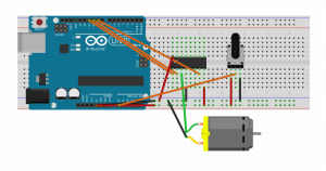
As my initial assignment 4 project (an abstract movement story that involved CAMs) did not end up working, I redid my assignment with a whole different concept and circuit. For my new story, I wanted to have a person be able to fly their own plane across the world, helping them travel to a place far beyond. To illustrate this, I made a DC motor rotate a disk upon which a plane hangs upon a cut out city scape.
I wanted the user to be able to control the speed at which the plane was rotating, so the user could help the plane “take off” and “land.” Thus, my circuit used a potentiometer and the h-bridge to give the user that level of control over the DC motor.
The main problems I had with this circuit was just getting h-bridge to work properly, as I think I had some connectivity issues with the chip and the breadboard. Overall though, this project ended with a visual story I was happy with and wasn’t too involved in terms of circuit debugging.
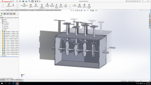
For my assignment, I wanted to tell a story through a simple automaton that would run off of CAMs. I worked on CADing the system up first to create a simple visual story; for my story, I wanted the watcher to visually see the CAMs turning moving with the motors and simply pushing wooden pegs up in a wave like motion.
Wanting to keep the circuit as simple as possible, I used a TIP20 motor and a DC wall plug to simply just power the motor and the Arduino code to just toggle the motor from being on and off.
I got the CAMs moving pretty successfully (in the video below).
However, when attaching my whole system together, unfortunately, there was a little bit too much friction and the top blocks would not line straight which led to problems. Trying to remedy this situation, with Ian’s advice, I hot glued marbles to the bottom of each block, but the issue of non straight blocks prevailed. Ultimately, if I were to do this project again, I would probably double up on my CAM thicknesses and maybe cut the system out of acrylic for a smoother system.
When first hearing about the prompt, I thought of the idea to create an octopus that would “spit out” ink when someone got too close, thus illustrating fear. I started along on my project with creating a laser cut octopus with two detached tentacles and an ink splotch with the intention of using servos to move the tentacles and ink splotch with servos. I then constructed my circuit and wrote my code and tested them without much difficulty – I had no real hardware or software bugs this time as the circuit was rather simple: the two tentacles would sweep constantly, unless someone came too close to the IR sensor which would trigger the ink splotch servo to spin out from under the octopus.
However, when attaching my pieces to my servo, I found only devastation. The pieces were far too heavy to move by the servo. Unfortunately, with the time I had left to complete the project, I thought the safest solution was to recreate the mechanical pieces by simple paper cut outs. In the end, I got a working project; however, it was a very unsatisfactory conclusion. If I were to redo this project again, I would either try again to maybe laser cut out cardboard pieces, as well as create better enclosures for the motors and the circuit so the servos would not create so much ambient movement.