So far, I have collected depth sensing data from the kinect, processes it (the 2D array of sensor data for each pixel is divided into blocks, and the average of the depth values in each block is calculated) and sent it to the arduino via serial connection.
Month: November 2017
Assignment 7: Rough Prototype- 3D Drawing Cube
For my project, I’ve gotten a few separate parts of my project to work, but not all of them.
Projector & Unity (Works)
Unity has this weird thing where there’s not a built-in way to get the full gaming experience while in the editor (or at least, I haven’t found one yet), but there’s a way to maximize the game scene, and if I set up my laptop to do the “extended projection”, it’s close enough to what I would want it to be. When I build the actual cube, if I make it slightly smaller than the projected image, it should be fine.
Projector & Cube (Works- kind of)
Unfortunately, the projector that I’m using doesn’t have the range that I wanted it to have (in terms of projecting within a close distance). The closest I can have an in-focus image is about 4 feet, so that scraps my idea of having the projector inside the cube and reflecting the image with a mirror. That takes away a huge component of the streamlined-ness that I wanted my final project to have, so I’ll try to make it up in other ways (perhaps a physical interface rather than a virtual one, etc.). I’ve finally gotten the dimensions for my cube as well – should end up being around 14″ x 16″, which means I might have to get stiffer cardstock when building it, I’m going to try to build it with what I have first.
Motor & Arduino (Doesn’t work yet)
This part is the most frustrating so far- I’ve spent hours trying to get my 12V stepper motor to work with Adafruit’s motor shield, but for some reason it’s just not working. I think that the issue might have to do with the power supply, but I’m not sure (will try to troubleshoot this some more in class). Without this key component working, I haven’t been able to work on getting Unity to interface with Arduino, which is what I see as the biggest challenge of the project, so this is definitely my top priority right now.
Leap Motion & Unity (Works)
Leap Motion has done a great job of streamlining its integration with Unity, so I’ve been able to get it to do the basic functions that I need so far (drawing, rotation with hand gestures, etc.).
Sorry I don’t have any pictures or videos- my phone camera died and I didn’t have time to check out a camera from Hunt beforehand.
Rough Crit
There are two technical sides to my project, one being the lights, and the other the sound. The sound code I have from my last project, so to reimpliment it will not be much of a problem. This will mostly consist of dealing with capacitance issues of longer wires, which should resolve itself through the use of a intermediary capacitance sensor (although I haven’t tested this yet).
The lights prove a little more challenging. I discussed with Jake Marsico his workflow on doing installations such as the one I’m attempting, and following his pointers have come up with the following. I’ve designed a passive animation in processing, and then will sample points on that animation, and send the RGB values out from processing. These will then be assigned to the correct light based on a csv file exported from the rhino layout of the entire project. I have not yet tested this full scale as I haven’t been able to acquire the lights or the fadecandy that I plan on using yet. However the animation and csv are created, and I’m confident that this workflow will work out in the end, espescially with cursory guidance from Jake.
Here is the animation that will be passively displayed on the LEDs behind the map: sketch_171116a
The next steps are definetly to begin with material tests and mock ups, I would have liked to do this sooner but wanted to wait until I had time to discuss the project with Slee.
Some changes that need to happen with the design are bringing in more of an aspect of realization about pittsburgh. Not necessarily education, but realizing something that was at the bounds of conciousness beforehand.
Assignment 7: Scott
For my project I wanted to incorporate text to speech in physical computing in order give the ability of speech through typing.
After looking online I believed I could use an old ps/2 port keyboard to work with the Arduino by soldering wires to the correct pins and then using a library to get the key presses in my code. After a lot of struggling with getting the connection between the pins and wires, I decided to order the piece that will make this connection much easier, by plugging into the port and giving the output wires that go into the Arduino. This part hasn’t arrived yet so for this stage of the assignment I used the Serial input from the computer’s keyboard in order to show my idea.
^when I realized that this was probably not going to work
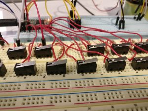
I found two text to speech libraries online for the Arduino, and incorporated both into my current project. The first library has the ability to take any string and will attempt to make the speaker speak it. It also has an adjustable pitch which I gave access to via buttons. To be honest, the outcome of this was a little disappointing. You can sort of tell what is being said, but its pretty hard to understand.
The second library I found had a bunch of pre-made words that it could say if initially written to memory. I use this library by having the speaker read the letters out that were typed. You can switch between these two modes with the switch on my breadboard.
To Do:
Currently, the volume is too low and I need to use an audio amplifier/bigger speaker to so that this will be audible in a noisy environment.
Once the ps/2 port that I ordered shows up, I will hopefully be able to interface with the ps/2 keyboard so that I don’t need to use the keyboard that the arduino is plugged into via USB. This will be nice because my final vision for this project is to not have it be plugged into a computer but standalone box with a keyboard and speaker and everything else tucked inside, including a power supply.
Assignment 7 – Rough Crit – Tatyana Mustakos
For my rough crit, I made an automaton that moves its head and hand. It also has shoulder rotation that allows it to rotate its arm, and well as tendons which allow it to reach out/ retract.
https://photos.app.goo.gl/khiN5u3OMJzX4H7g2
https://photos.app.goo.gl/4w65Jl4bumMZOUW33
I made the face and hand out of paperclay, and the arm and body out of cardboard for this version. I will construct the final completely out of paper clay so that the aesthetics are more cohesive.
For the final version I want to have it so that the piece is still, but once someone holds their hand out to it, it looks up a bit and reaches out to touch their hand
code:
/*
* servo movement
* Tatyana Mustakos
*/
#include
Servo myservo; // create servo object to control a servo
// twelve servo objects can be created on most boards
Servo myservo1;
int pos = 0; // variable to store the servo position
int pos1 =0;
void setup() {
myservo.attach(9); // attaches the servo on pin 9 to the servo object
myservo1.attach(10);
}
void loop() {
for (pos = 0; pos = 0; pos -= 1) { // goes from 180 degrees to 0 degrees
myservo.write(pos); // tell servo to go to position in variable ‘pos’
delay(15); // waits 15ms for the servo to reach the position
}
for (pos1 = 0; pos1 = 0; pos1 -= 1) { // goes from 180 degrees to 0 degrees
myservo1.write(pos1); // tell servo to go to position in variable ‘pos’
delay(15); // waits 15ms for the servo to reach the position
}
}
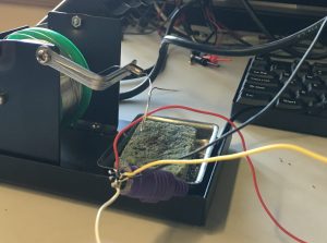
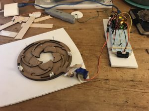
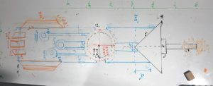
My other project (sorry i couldnt pick) is a radial plotter, it draws images but is restricted to only curved brush strokes. the pen is attatched to an arm that can extend or retract (this affects the distance from the plotter itself, or the origin point), and can rotate side to side. This project is an experimentation of a sort of reverse computer vision, instead of traditional vector plotters, I wanted to focus more on the brush stroke (fake sketch prototype below)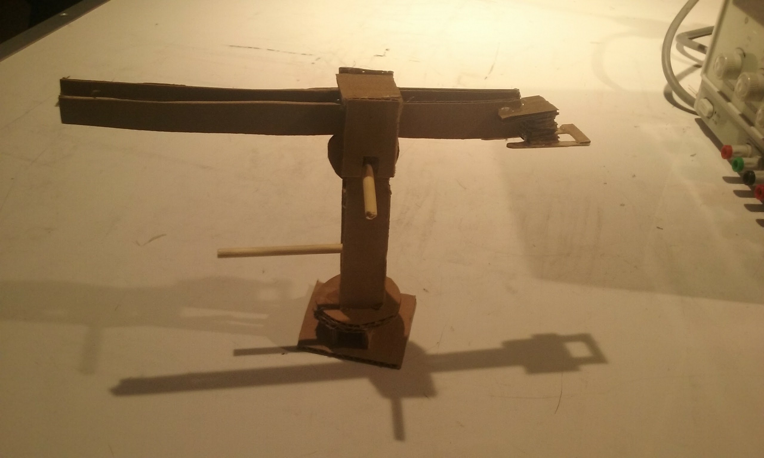
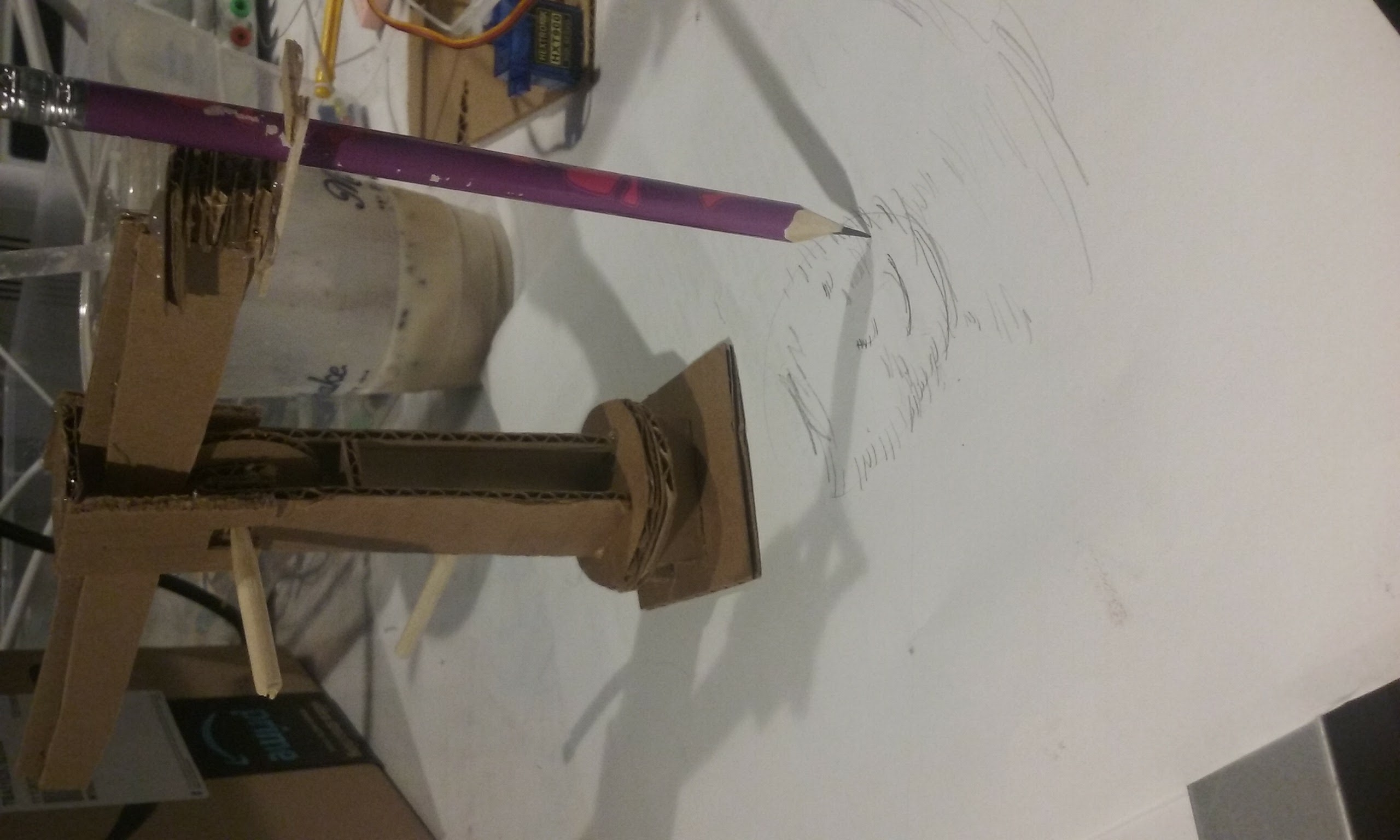
I created a working(aside from the gear and inward rotary) prototype that extends and rotates around the base axis. I have working pieces and will laser cut them so that they function smothely. The arm can extend due to a motor rotating the gear, the pen will move up and down based on an actuator (with a mechanism simiair to a pen clicker), and the base will rotate with a servo (since it doesnt need to rotate more than 180 degrees).
I will implement drawing through processing and the load pixels function, calculating which line/curve segments the plotter should draw.
Another interesting thing that will occur is seeing what will happen/ how the image will draw differently based on where the plotter is placed
Assignment 7 – Rough Crit Update
I decided to do an installation that involved 3 pieces of ‘technology enhanced’ silverware.
I got 2/3 of the prototypes working, the third prototype needs another redesign, and I plan to finish the CAD for this over the break to make up for lost time. If I can’t get this working by this Saturday, I’ll just 3D print a design that I know will work, and then polish that up.
First Prototype – Nervous Fork:
Todo for Fork:
-Test with big and small fork, to make sure servo is able to carry the weight of the fork.
-Install a handle with a battery pack + microcontroller
-Use rubber/some kind of firm material to keep fork firm when string isn’t being pulled
-Use stronger wire/string
Second Prototype – The Continuous Spoon:
Todo with Spoon:
-Cut off heads of spoons so that only heads rotate
-Design a handle and way to conceal the motor
-Get better/smaller motor, as current one has crooked shaft
-Solder on switch to turn it on and add a battery pack
Second Prototype – Jig-knife:
Current issue: Center/arm that attaches to small gear isn’t the correct length or is a little bit off center, causing the gear to swing in a non-circular shape. I need to carefully design this gearbox to ensure that everything is at a fixed distance so the gears will mesh properly.
Todo with Gearbox:
-Redesign lasecut gearbox
-3D print working gearbox as a fall-back
– Make nice casing for gear box and attach knife to piston
-Add on switch and battery
-Pick a stronger and faster motor to handle force of meshing gears
-Add handlebars to hold jigsaw knife
OPTIONAL (Given time):
– Add FSR to plate, and send (text or tweet) messages about weight of food on plate.
Digital Fish Tank
For this draft, I modified my initial concept a bit. Instead of having a “smart” fish tank that responds to texts/messages, I’ve decided to make a digital interface for a fish tank that is child-friendly. It will control the same elements as I planned, but possess different inputs.
The switches and buttons I’ve used in past projects are functional, but I’m not a huge fan of their form. While I could modify them/ work around that, instead I’ve chosen to make my own switches using conductive tape — ultimately they’re going to be tile-shaped, but they’re currently not much more than functional. Which leads me to…
Currently my project has about no form, but my end project will have the shape of a fish and more intuitive interactions. I also plan on adding in a water pump, but it’s not currently added to the project because the pump I plan on using is at home and I’m going to bring it back with me after break. Flow rate will be controlled by a row of sensors to measure speed (either hand-made like the switches (which would just be three switches in a row with one tile) or with capacitive touch sensors, if I can get them to work well and look good).


Assignment 7: Gaurav
My idea is to make a keyboard that is a symbol for confusion. It’s exterior will look perfectly alright but on playing it, the user will find that the keys produced tones completely different from what they expect. And the tone that each note plays varies in random time and there should be no seeming pattern in the confusion. However, there will be brief periods were the keyboard will be lucid again – allowing the user to savor the few moments of normalcy before it is consumed again by its confusion.
The project as it stands lacks form. I decided to focus on making the essentials work and efficient code for the first draft of this project. An Arduino Teensy is used to create different types of waveforms that can be outputted through its DAC. The signal from the DAC is amplified using a standard 2.5 W Class D amplifier that then connects to the speaker. The Audio library proved to be extremely helpful in the creation and the handling of the waveforms. It took a lot of time and effort to troubleshoot and create the output of waves from the DAC and then in using the amplifier chip. However, many trivial but crucial mistakes were found that when fixed allowed the system to work quite well.
Writing the code has been one of the more challenging parts of this project. I have learnt a lot from observing how changing code in one part of the program can affect the function of all other parts. Also, I noticed that every time I added a functionality in the code, there were new edge cases that I needed to account for. This has been a great learning experience.
The next thing I want to focus on is the form of the project. My ideal path forward would be to obtain an old, cheap keyboard and strip off most of the electronics to access just the keys. I would then be able to connect the keys from the Arduino and control the sound exactly the way I described above. If this proves to be very hard, I would like to fabricate a simple but appealing keyboard using laser cut wood or acrylic.
Video 1: Perfect Sine-wave based polyphonic synthesizer
Video 2: Confused Piano
Assignment 07:
Updated Hourglass Concept:
An hourglass that resembles how time is passing in its environment. The speed of sand falling depends on how much movement occurs around it.
Rough Draft Prototype:
Sketches are developed that outline the overall form of the hourglass, including how the technology will be embedded in the form. I used a previously made model of a laser cut aperture to change the amount of sand that will potentially flow through. I still need to add another cover for the lens so the pieces do not fall out, especially when the hourglass is flipped. I also need to solidify how the tech will be securely (drilled?) into the wooden casing. I am also considering adding another variable (ex. sound) to control how the sand will fall (not sure if it will get too complicated if I want to affect how the sand falls, rather than just the amount of sand falling).
To Do:
- design the enclosure that will hold the glass form
- Have people test out form and see if it is understandable / has the right affordances
- Fix all the things that didn’t work
- repeat 7 and 8 with a few other people
- make an information poster for the final show
- write up my artist’s statement for the final show
Transistor Sword Rough Crit
https://drive.google.com/drive/folders/1Xv4OfpfIbuqn6w5a-yl5K2HX8IPY0XIM?usp=sharing
Difficulties:
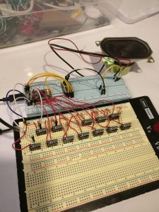
Transistors:It so turns out that the MOSFETs were not very functional transistors, and a Darlington Array transistor (UM2003) was used instead. Independent continuity of each R, G, B, pin and MOSFET circuit was tested, but there seemed to be a perpetual issue with connectivity. The lights responded well to code after the switch to the Darlington Array transistor.
Pulse Sensor: The pulse sensor used the code from Pulsesensor.com but the threshold was set at 550, while the readings from the pulse sensor ranged from 900 to 10, since there was much noise. Even if someone’s hand was close but not on the sensor, a “pulse” was detected. To prevent the lights from pulsing when there was only noise and no real pulse, I included another pulseSwitch, a momentary switch that had to be activated, in addition to the corruptSwitch being inactive.
Getting Corrupt Mode (corruptSwitch == LOW) to stay red: I have some trouble writing the code to exit the loop and end with the LEDs staying in the red state. I tried using booleans and conditionals but can not seem to get it right.
The circuitry has been completed for this project but the code could use some tweaks.