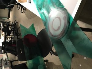
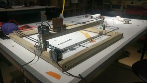
My final project is the Koi fish table. It is basically a Laser Cutter set up. However, I wanted to use wood and acrylic to make the setup so that it would be: 1. cheaper in cost of materials; 2. easier to get materials
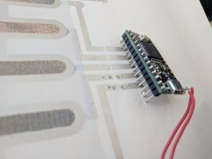
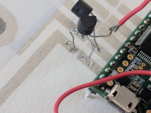
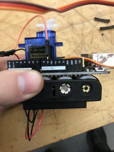
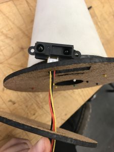
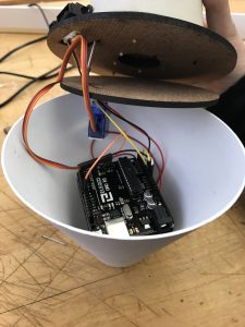
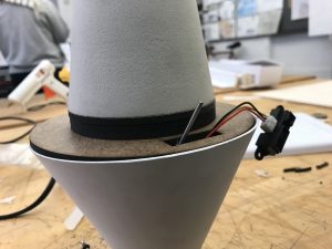
The coponent in this project is consist of 2 stepper motors, 3 timing belts, 3 sets of “wheels”, and several wood beams for the structure.
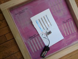
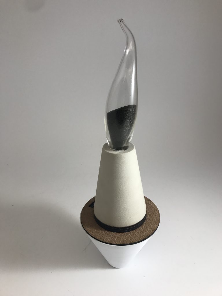
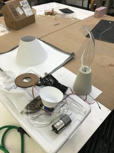
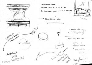
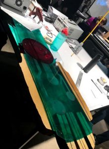
Here is the setup:
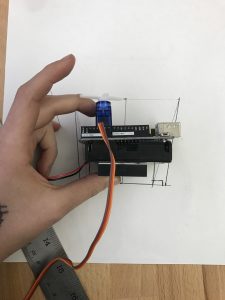
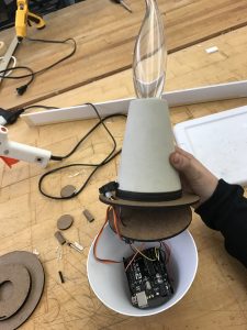
When it is running:
Here is the code:
/*This is the Code for controlling the stepper motors
 Some part of the code is adapted from the sample sketch from
 "Stepper Test code from Adafruit tutorial

This code might not work with any other shielf but
 "Adafruit Motor Shield v2"
 ----> http://www.adafruit.com/products/1438
*/


#include <Wire.h>
#include <Adafruit_MotorShield.h>
#include "utility/Adafruit_MS_PWMServoDriver.h"

// Create the motor shield object with the default I2C address
Adafruit_MotorShield AFMS = Adafruit_MotorShield();

// Connect a stepper motor with 200 steps per revolution (1.8 degree)
// to motor port #1(M1 and M2) and another one to #2 (M3 and M4)
Adafruit_StepperMotor *motorX = AFMS.getStepper(200, 2);
Adafruit_StepperMotor *motorY = AFMS.getStepper(200, 1);

int motorSpeed = 100; //# rpm
int XYPosMax = 2000; //200 step per rev, 10 full rev max
int XYPosMin = 0; //whole table is a 2000 by 2000 grid


int curPosX = 0;
int curPosY = 0;

int koiDir = 0;
int koiMove = 0;

int moveX = 0;
int moveY = 0;

int yellowPin = A3;
int bluePin = A0;
int greenPin = A1;
int redPin = A2;

int yellowPre = 0;
int yellowCur = 0;
int greenPre = 0;
int greenCur = 0;
int bluePre = 0;
int blueCur = 0;
int redPre = 0;
int redCur = 0;


int threshHoldDiff = 150;


void setup() {
 // put your setup code here, to run once:
 Serial.begin(9600);
 AFMS.begin(); // create with the default frequency 1.6KHz
 //AFMS.begin(1000); // OR with a different frequency, say 1KHz
 motorX->setSpeed(motorSpeed);
 motorY->setSpeed(motorSpeed);


 yellowPre = analogRead(yellowPin);


}


void touchThePond(){
 yellowCur = analogRead(yellowPin);
 grennCur = analogRead(greenPin);
 blueCur = analogRead(bluePin);
 redCur = analogRead(redPin);

//yellow here (all same setup, different place
 if (abs(yellowCur - yellowPre) > threshHoldDiff){
 //yellow is x = 0, y = 0

moveX = curPosX;
 moveY = curPosY;

 motorX->step(moveX, FORWARD, MICROSTEP)
 motorY->step(moveY, BACKWARD, MICROSTEP)
 }

//blue

//green

//red
}


void moveKoiRand() {
 //First, pick a direction
 //Then decide how much wanna go
 koiDir = random(0, 4); //0 = +X, 1 = -X, 2 = +Y, 3 = -Y
 koiMove = random(50, 401); //small "steps" to mimic fish movement
//
// Serial.print("koiDir = ");
// Serial.print(koiDir);
// Serial.print("; koiMove = " );
// Serial.println(koiMove);
//
// Serial.print("curPosX = ");
// Serial.print(curPosX);
// Serial.print("curPosY = ");
// Serial.println(curPosY);

if (koiDir == 0) {

//check the legality of the position first;
 if ((curPosX + koiMove) >= XYPosMax) {
 moveX = XYPosMax - curPosX; //move to the edge
 }
 else {
 moveX = koiMove;
 }

// Serial.print("in case 0, moveX= ");
// Serial.print(moveX);
 motorX->step(moveX, BACKWARD, MICROSTEP); // moving +X is

curPosX += moveX; //update the new position data;
// Serial.print("in case 0, curPosX= ");
// Serial.println(curPosX);
 }

if (koiDir == 1) {

if ((curPosX - koiMove) <= XYPosMin) {
 moveX = curPosX;
 }
 else {
 moveX = koiMove;
 }

// Serial.print("in case 1, moveX= ");
// Serial.print(moveX);
 motorX->step(moveX, FORWARD, MICROSTEP);

curPosX -= moveX;
// Serial.print("in case 1, curPosX= ");
// Serial.println(curPosX);
 }


if (koiDir == 2) {
 if ((curPosY + koiMove) >= XYPosMax) {
 moveY = XYPosMax - curPosY; //move to the edge
 }
 else {
 moveY = koiMove;
 }
//
// Serial.print("in case 2, moveY= ");
// Serial.print(moveY);
 motorY->step(moveY, FORWARD, MICROSTEP);

curPosY += moveY;
// Serial.print("in case 2, curPosY= ");
// Serial.println(curPosY);
 }

if (koiDir == 3) {
 if ((curPosY - koiMove) <= XYPosMin) {
 moveY = curPosY;
 }
 else {
 moveY = koiMove;
 }

// Serial.print("in case 3, moveY= ");
// Serial.print(moveY);
 motorY->step(moveY, BACKWARD, MICROSTEP);

curPosY = curPosY - moveY;

// Serial.print("in case 3, curPosY= ");
// Serial.println(curPosY);
 }

}


void loop() {
 // put your main code here, to run repeatedly:
 Serial.println("Microstep steps");
 moveKoiRand();


}
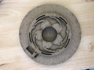
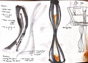
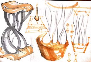
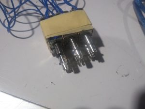
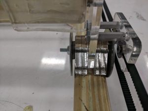
Design of the “Wheel”:

Reflection:
The really hard part of this project is to make the mechanical setup. I spent more than a week working on solidworks. However, the setup is too big and not as percise as I hoped it would be. Therefore, there are a lot of problem while working in the wood shop initially. Later I gave up on following soliworks, and just try and test laser cutting and wood working.
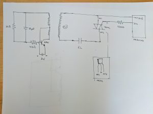
Another part that is complicated is to make the stepper work. The Arduino shield is nice, for controlling the stepper. The libaray it came with helps me to reduced a lot of time for me trying to figure out how to work with stepper (even though it still took a long time for me to understand how stepper works). The other problem that I faced is that the stepper doesn’t come with avaliable datasheet (I coudn’t find anything). However, the shield was nice enough that I tried out a few different voltage input using a controllable power output for the stepper. Finally, I found out that the stepper needs 1.5A at 5V which is a lot higher than normal power supply. At last I used 2.4A at around 8V to power the stepper to make sure it can over come the friction it might experience.
The problem that I didn’t really solve in this project is how to change the stepper speed. Even the Adafruit library include speed settings, the stepper speed couldn’t be changed for some reason.
If I were to do this project again, I will add a set of caliberation setting. I will mount limit switches on the zero of X and Y axis. So I don’t need to hand calibrate to zero position everytime it restarts. However, that need me to figure out how to program the stepper to move without having to tell it how much it needs to move.